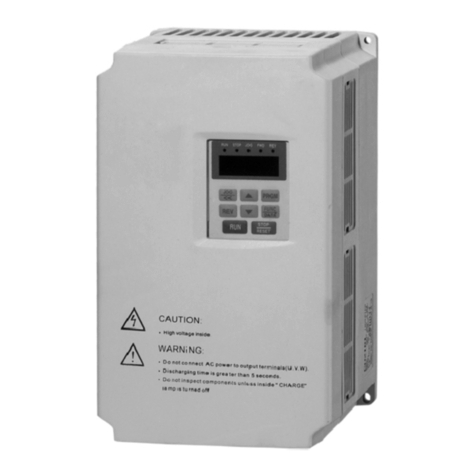
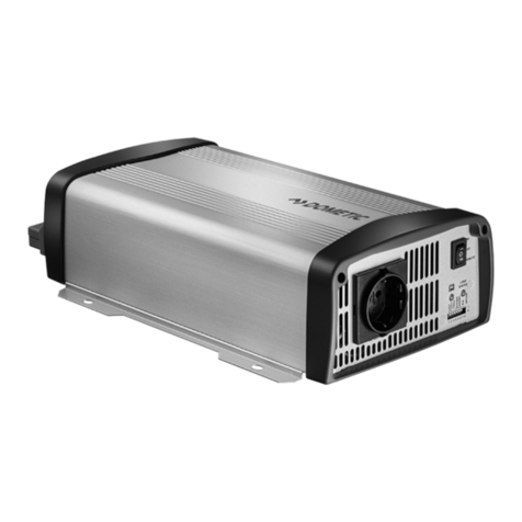
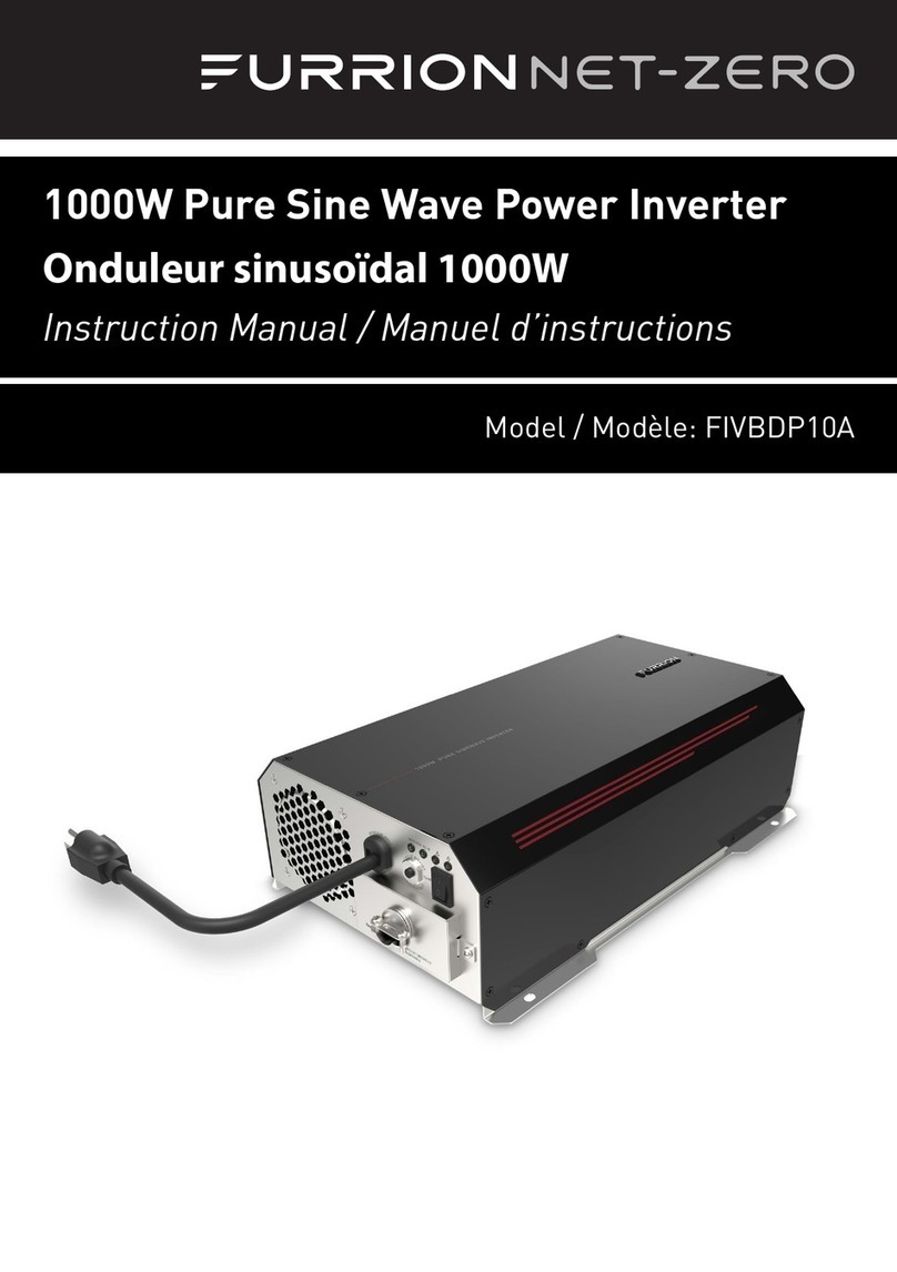
Advanced Control C220 Series User manual


C220/C420 General Flux Vector Control Inverter User Manual
1
Contents
PREFACE................................................................................4
CHAPTER1 SAFETYAND PRECAUTIONS.....................7
1.1 SAFETY PRECAUTIONS ..................................................... 7
1.2 PRECAUTIONS ................................................................ 10
CHAPTER 2 PRODUCT INFORMATION.......................14
2.1 DESIGNATION RULES ..................................................... 14
2.2 NAMEPLATE................................................................... 14
2.3 SERIES OF INVERTER C220/C420 ................................... 15
2.4 TECHNICAL SPECIFICATIONS ......................................... 15
2.5 PHYSICAL APPEARANCE AND DIMENSIONS OF MOUNTING
HOLE ................................................................................... 19
2.6 ROUTINE REPAIR AND MAINTENANCE OF INVERTER ..... 25
2.7 INSTRUCTIONS ON WARRANTY OF INVERTER ................ 27
2.8 GUIDE TO MODEL SELECTION ........................................ 27
2.9 GUIDE TO SELECTION OF BRAKE COMPONENTS ............. 28
CHAPTER 3 MECHANICALAND ELECTRICAL
INSTALLATION ..................................................................29
3.1 MECHANICAL INSTALLATION ........................................ 29
3.2 ELECTRICAL INSTALLATION ........................................... 33
CHAPTER 4 OPERATION AND DISPLAY......................44
4.1 INTRODUCTION TO OPERATION AND DISPLAY INTERFACE
............................................................................................ 44
4.2 DESCRIPTION OF FUNCTION CODE VIEWING AND
MODIFICATION METHODS ................................................... 49
4.3 METHOD OF VIEWING STATUS PARAMETERS ................ 50

C220/C420 General Flux Vector Control Inverter User Manual
2
4.4 PASSWORD SETTING ...................................................... 51
4.5 AUTOMATIC TUNING OF MOTOR PARAMETERS ............. 53
CHAPTER 5 PARAMETER DESCRIPTION...................55
5.1 GROUP F0 BASIC FUNCTION .......................................... 55
5.2 GROUP F1 START/STOP CONTROL................................... 68
5.3 GROUP F2 V/F CONTROL PARAMETERS ........................ 75
5.4 GROUP F3 VECTOR CONTROL PARAMETERS ................. 80
5.5 GROUP F4 MOTOR PARAMETERS ................................... 85
5.6 GROUP F5 INPUT TERMINAL .......................................... 89
5.7 GROUP F6 OUTPUT TERMINAL .................................... 101
5.8 GROUP F7 AUXILIARY FUNTION AND MAN-MACHINE
INTERFACE FUNCTION ....................................................... 106
5.9 GROUP F8 COMMUNICATION PARAMETER DESCRIPTION
.......................................................................................... 118
5.10 GROUP F9 FAULT AND PROTECTION .......................... 120
5.11 GROUP FA PROCESS CONTROL PID FUNCTION ......... 126
5.12 GROUP FB SWING FREQUENCY ................................. 131
5.13 GROUP FC MS SPEED FUNCTION AND SIMPLE PLC
FUNCTION .......................................................................... 134
5.14 GROUP FD,FE (RESERVED) ........................................ 143
5.15 GROUP FF FACTORY PARAMETER ............................. 143
CHAPTER6 EMC(ELECTROMAGNETIC
COMPATIBILITY)..........................................................144
6.1 DEFINITION .................................................................. 144
6.2 STANDARD DESCRIPTION ............................................. 144
6.3 EMC GUIDE ................................................................ 145
CHAPTER 7 FAULT DIAGNOSISAND
COUNTERMEASURES ....................................................150

C220/C420 General Flux Vector Control Inverter User Manual
3
7.1 FAULT ALARM AND COUNTERMEASURES .................... 150
7.2 COMMON FAULT AND RESOLUTION ............................. 165
CHAPTER 8 C220/C420 SERIES SERIAL PORT
COMMUNICATION PROTOCOL ..................................167
8.1 ABOUT PROTOCOL ....................................................... 167
8.2 APPLICATION MODE ..................................................... 167
8.3 BUS STRUCTURE .......................................................... 168
8.4 PROTOCOL SPECIFICATION ........................................... 168
8.5 COMMUNICATION FRAME STRUCTURE ......................... 169
8.6 CYCLICAL REDUNDANCY CHECK ................................ 173
8.7 CMD AND STATUS ...................................................... 175
APPENDIX:FUNCTION PARAMETER TABLE...........178

Preface General Flux Vector Control Inverter User Manual
4
Preface
Thank you for purchasing C220/C420 series Flux Vector Control Inverter.
C220/C420 series Inverter which is a new generation of modular can flexibly
satisfy customers’ individual requirements and industry demand by extension of
design on the premise that meet general purpose of the customers , representing the
tendency of applying in the future inverters industry. In meeting to the requirements
of all kinds of complicated high precision transmission with all functions of built-in
universal extended interface, power speed control, torque control ,practical process
closed-loop control, simple PLC ,flexible I/O terminal, pulse frequency
given ,frequency given channel and run command channel bundled, main auxiliary
given control ,swing frequency control ,speed track ,encoder break monitoring,
internal break unit ,28 species fault monitoring, more than 16 MS speed control,
parameters copies ,etc, at the same time, it provides equipment manufacturer with an
all in-one solution of high integration ,on reducing system cost and improving
system reliability have a great value.
Tab.1 C220/C420 functional modules
C220/C420
:General Magnetic Flux Vector
Control Inverter
Input/Output terminal 4×DI(bidirectional input non-high speed),
2×AI,1×DO,1×AO,1×Relay
Control mode
open loop magnetic flux vector 1
open loop magnetic flux vector 2
V/F
control motor AC asynchronous motor

General Flux Vector Control Inverter User Manual Preface
5
expansion function of specialized
industrial module none
I/O expansion card none
PG card none
fixed-length control none
communication function Modbus (485 communication standard)
switching function of two motor
parameters
none
compared with traditional voltage vector control ,current vector control gains
main advantages as follow :
1、start torque:0.5Hz,180% rated torque(open loop magnetic flux vector
control );
2、Flux-weakening control algorithm, maximum can exceed 2 times the
fundamental frequency operation of motor;
3、precise speed control accuracy: open loop magnetic flux vector control
≤±0.5%(rated sync-speed),close loop magnetic flux vector control
≤±0.2%(rated sync-speed);
4、more stable speed control stability: open loop magnetic flux vector control
≤±0.3(rated sync-speed), close loop magnetic flux vector control≤±0.1%
(rated sync-speed);
5、faster torque response performance ≤40ms (open loop magnetic flux vector
control);≤20ms (close loop flux vector control).
This manual is a guide to the operations of C220/C420control
module .Regarding the operation of C220/C420 control module , please read it for
details.

Preface General Flux Vector Control Inverter User Manual
6
This manual provides the user with precautions and instructions concerning the
prototyping , installation, parameter setting, on-site commissioning ,fault diagnosis,
routine repair and maintenance of inverter. Please read the instruction manual
carefully before the proper use of C220/C420 series inverter , and stay keeping it for
the future use. The supporting equipment customers shall distribute this manual
together with equipment to the final users .
Unpacking and Inspection
Please confirm carefully when unpacking the box:
1、If the model and inverter rated values on the nameplate are the same as
your order. The box contains the equipment certificate of conformity, user manual
and warranty card
2、If the product is damaged during the transportation, please contact our
company or the supplier immediately if there is any omission or damage.
First time use :
The users who use the product for first time shall read this manual
carefully .For any doubt about certain functions and performances, please contact
the technical support personnel of our company for help so as to use the product
properly.
The information our company provides are subject to change without additional
notice due to the constant improvement of the inverter products .
C220/C420 series inverter is accordance with international standards , and have
passed in CE standards
IEC/EN61800-5-1: Safety Regulation on Commissionable Electric Drive System
IEC/EN61800-3: Commissionable Electric Drive System,
Third Part : Electromagnetic Compatibility Standard and Specific Testing Method
for the Products

Safety and precautions
C220/C420 General Flux Vector Control Inverter User Manual
7
Chapter1 safety and precautions
Safety definition:
In this manual, safety precautions are divided into two types below:
!
Danger
Danger arising due to improper operations may cause severe hurt or even death.
Caution
!
Danger arising due to improper operations may cause moderate hurt or light hurt or
equipment damage.
1.1 Safety precautions
1.1.1 Before Installation:
!
Danger
1. Do not use the damaged inverter or inverter with missing parts. Otherwise,
there may be risk of injury.
2. Use the motor with Class B or above insulation. Otherwise, there may be risk
of electric shock.
1.1.2 During the Installation:
!
Danger
1. Mount the inverter on incombustible surface like metal, and keep away from
flammable substances. Otherwise it may cause fire.
Caution
!
2. When more than two inverters are to be installed in one cabinet, due attention
shall be paid to the installation locations (refer to Chapter 3 Mechanical and
Electrical Installation) to ensure the heat sinking effect.
3. Do not drop the lead wire stub or screw in the inverter. Otherwise it may
damage the inverter.

Safety and precautions
C220/C420 General Flux Vector Control Inverter User Manual
8
1.1.3 During wiring:
!
Danger
1. Operation shall be performed by the professional engineering technician.
Otherwise there will be danger of electric shock!
2. There shall be circuit breaker between the inverter and power supply.
Otherwise, there may be fire!
3. Make sure the power is disconnected prior to the connection. Otherwise there
will be danger of electric shock!
4. The earth terminal shall be earthed reliably. Otherwise there may be danger of
electric shock.
Caution
!
1.1.4 Before Power-on:
!
Danger
1. Please confirm whether the power voltage class is consistent with the rated
voltage of the inverter and whether the I/O cable connecting positions are
correct, and check whether the external circuit is short circuited and whether
the connecting line is firm. Otherwise it may damage the inverter. The cover
must be well closed prior to the inverter power-on. Otherwise electric shock
may be caused.
2. The cover must be well closed prior to the inverter power-on. Otherwise
electric shock may be caused!
Caution
!
3. The inverter is free from dielectric test because this test is performed prior to
the delivery. Otherwise accident may occur!
4. Whether all the external fittings are connected correctly in accordance with the
circuit provided in this manual. Otherwise accident may occur!
1.1.5 Upon Power-on
!
Danger
1. Do not open the cover of the inverter upon power-on. Otherwise there will be
danger of electric shock!
2. Do not touch the inverter and its surrounding circuit with wet hand. Otherwise

Safety and precautions
C220/C420 General Flux Vector Control Inverter User Manual
9
there will be danger of electric shock!
3. Do not touch the inverter terminals (including control terminal).Otherwise
there will be danger of electric shock!
4. At power-on, the inverter will perform the security check of the external
heavy-current circuit automatically. Thus, at this time please do not touch the
terminals U, V and W, or the terminals of motor, otherwise there will be
danger of electric shock.
Caution
!
5. If parameter identification is required, due attention shall be paid to the danger
of injury arising from the rotating motor. Otherwise accident may occur!
6. Do not change the factory settings at will. Otherwise it may damage the
equipment!
1.1.6 During the operation:
!
Danger
1. Do not close to the machinery and equipment if select restart function.
Otherwise, personal injury may be caused!
2. Do not touch the fan or discharge resistor to sense the temperature. Otherwise,
you may get burnt!
3. Detection of signals during the operation shall only be conducted by qualified
technician. Otherwise, personal injury or equipment damage may be caused!
Caution
!
4. During the operation of the inverter, keep items from falling into the
equipment. Otherwise, it may damage the equipment!
5. Do not start and shut down the inverter by connecting and disconnecting the
contactor. Otherwise, it may damage the equipment!
1.1.7 During Repair
!
Danger
1. Do not repair and maintain the equipment with power connection. Otherwise
there will be danger of electric shock!
2. be sure to conduct repair and maintenance after the charge LED indicator of the

Safety and precautions
C220/C420 General Flux Vector Control Inverter User Manual
10
inverter is OFF. Otherwise, the residual charge on the capacitor may cause personal
injury!
3. The inverter shall be repaired and maintained only by the qualified person who
has received professional training. Otherwise, it may cause personal injury or
equipment damage!
1.2 Precautions
1.2.1 Motor Insulation Inspection
When the motor is used for the first time, or when the motor is reused after
being kept, or when periodical inspection is performed, it shall conduct motor
insulation inspection so as to avoid damaging the inverter because of the insulation
failure of the motor windings. The motor wires must be disconnected from the
inverter during the insulation inspection. It is recommended to use the 500V mega
meter, and the insulating resistance measured shall be at least 5MΩ.
1.2.2 Thermal Protection of the Motor
If the ratings of the motor does not match those of the inverter, especially
when the rated power of the inverter is higher than the rated power of the motor, the
relevant motor protection parameters in the in the inverter shall be adjusted, or
thermal relay shall be mounted to protect the motor.
1.2.3 Running with Frequency higher than Standard Frequency
This inverter can provide output frequency of 0Hz to 400Hz. If the user needs
to run the inverter with frequency of more than 50Hz, please take the resistant
pressure of the mechanical devices into consideration.
1.2.4 Vibration of Mechanical Device
The inverter may encounter the mechanical resonance point at certain output
frequencies, which can be avoided by setting the skip frequency parameters in the
inverter.

Safety and precautions
C220/C420 General Flux Vector Control Inverter User Manual
11
1.2.5 Motor Heat and Noise
Since the output voltage of inverter is PWM wave and contains certain
harmonics, the temperature rise, noise and vibration of the motor will be higher than
those when it runs at standard frequency.
1.2.6 Voltage-sensitive Device or Capacitor Improving Power Factor at the
Output Side
Since the inverter output is PWM wave, if the capacitor for improving the
power factor or voltage-sensitive resistor for lightning protection is mounted at the
output side, it is easy to cause instantaneous over current in the inverter, which may
damage the inverter. It is recommended that such devices not be used.
1.2.7 Switching Devices like Contactors Used at the Input and Output terminal
If a contactor is installed between the power supply and the input terminal of
the inverter, it is not allowed to use the contactor to control the startup/stop of the
inverter. If use of such contactor is unavoidable, it shall be used with interval of at
least one hour. Frequent charge and discharge will reduce the service life of the
capacitor inside the inverter. If switching devices like contactor are installed
between the output end of the inverter and the motor, it shall ensure that the on/off
operation is conducted when the inverter has no output. Otherwise the modules in
the inverter may be damaged.
1.2.8 Use under voltage rather than rated voltage
If the C220/C420 series inverter is used outside the allowable working
voltage range as specified in this manual, it is easy to damage the devices in the
inverter.
When necessary, use the corresponding step-up or step-down instruments to
change the voltage.
1.2.9 Change Three-phase Input to Two-phase Input
It is not allowed to change the C220/C420 series three-phase inverter into
two-phase one. Otherwise, it may cause fault or damage to the inverter.

Safety and precautions
C220/C420 General Flux Vector Control Inverter User Manual
12
1.2.10 Lightning Impulse Protection
The series inverter has lightning over current protection device, and has
certain self-protection capacity against the lightning. In applications where lightning
occurs frequently, the user shall install additional protection devices at the front-end
of the inverter.
1.2.11 Altitude and Derating
In areas with altitude of more than 1,000 meters, the heat sinking effect of the
inverter may turn poorer due to rare air. Therefore, it needs to derate the inverter for
use. Please contact our company for technical consulting in case of such condition.
1.2.12 Certain Special Use
If the user needs to use the inverter with the methods other than the
recommended wiring diagram in this manual, such as shared DC bus, please consult
our company.
1.2.13 Note of Inverter Disposal
The electrolytic capacitors on the main circuit and the PCB may explode
when they are burnt. Emission of toxic gas may be generated when the plastic parts
are burnt. Please dispose the inverter as industrial wastes.
1.2.14 Adaptable Motor
1) The standard adaptable motor is four-pole squirrel-cage asynchronous induction
motor. If such motor is not available, be sure to select adaptable motors in according
to the rated current of the motor. In applications where drive permanent magnetic
synchronous motor is required, please consult our company;
2) The cooling fan and the rotor shaft of the non-variable-frequency motor adopt
coaxial connection. When the rotating speed is reduced, the cooling effect will be
poorer. Therefore, a powerful exhaust fan shall be installed, or the motor shall be
replaced with variable-frequency motor to avoid the over heat of the motor.
3) Since the inverter has built-in standard parameters of the adaptable motors, it is

Safety and precautions
C220/C420 General Flux Vector Control Inverter User Manual
13
necessary to perform motor parameter identification or modify the default values so
as to comply with the actual values as much as possible, or it may affect the running
effect and protection performance;
4) The short circuit of the cable or motor may cause alarm or explosion of the
inverter. Therefore, please conduct insulation and short circuit test on the newly
installed motor and cable. Such test shall also be conducted during routine
maintenance. Please note that the inverter and the test part shall be completely
disconnected during the test.

Product Information
C220/C420 General Flux Vector Control Inverter User Manual
14
Chapter 2 Product Information
2.1 Designation Rules
CM530 A 4T 4R0 G B / 5R5 P B
Inverter Series
Voltage Level
2S:Single Phase 110V
3S:Single Phase 220V
3T:Three Phase 220V
4T:Three Phase 380V
7T:Three Phase 690V
……
Design edition A
Design edition B
Design edition C
……
Model
Adaptable Motor Power
Mark: R75 1R5 …… 011 015
Motor PowerKW)0.75 1.5 …… 11 15
Brake Unit
B:Including Brake Unit
NULL:None
G:Gerneral Type
P:Fan Pump Type
Fig.2-1
2.2 Nameplate
Fig.2-2 Nameplate

Product Information
C220/C420 General Flux Vector Control Inverter User Manual
15
2.3 Series of Inverter C220/C420
Tab.2-1 C220/C420 Inverter Model and Technical Data
Inverter model Input
voltage(V)
Input
current
(A)
Output
current(A)
Adaptable
Motor(kW)
ADV 0.40 C220-M
Single
Phase
220V
Range:
-
15% to
20%
5.4 2.3 0.4
ADV 0.75 C220-M 8.2 4.0 0.75
ADV 1.50 C220-M 14.0 7.0 1.5
ADV 0.75 C420-M
Three Phase
380V
Range:
-
15% to
20%
3.4 2.1 0.75
ADV 1.50 C420-M 5.0 3.8 1.5
ADV 2.20 C420-M 6.2 5.1 2.2
2.4 Technical Specifications
Tab.2-2 C220/C420 Inverter Technical Specifications
Item
Specifications
Maximum
frequency
400Hz
Carrier Frequency
1k to 15kHz; the carrier frequency will be
automatically
adjusted according to the load characteristics.
Input frequency
resolution
Digital setting: 0.01Hz
Analog setting: maximum frequency ×0.1%

Product Information
C220/C420 General Flux Vector Control Inverter User Manual
16
Item
Specifications
Basic
function
Control mode
V/F control
Vector flux
control 1
Vector flux control 2
Startup torque 0.5Hz/180%(Open loop Vector flux control)
Speed adjustment
range
1:200(Open loop Vector flux control)
Speed precision Open loop Vector flux control:≤±0.5%
Speed stability
Open loop Vector flux control
:
≤±0.3%
Overload capacity 150% rated current 60s; 180% rated current 3s
Torque hoist
Automatic torque hoist; manual torque hoist 0.1% to
30.0%
V/F curve Linear V/F, Multi-point V/F, and Square V/F
Speed-up and
Speed-down curve
Straight line or S curve speed-up and speed-down
mode; Two kinds of speed-up and speed-down
time; Speed-up and speed-
down time ranges between
0.0s
to 3000.0S.
DC brake
DC brake frequency: 0.00Hz to maximum frequency;
brake time:
0.0s to 36.0s,and brake current value:
0.0% to 100.0%.
Jog control
Jog frequency range:0.00Hz to 50.00Hz;jog
speed-up/speed-down time: 0.0s to 3000.0s.
Simple PLC and
MS speed running
It can realize a maximum of 16 segments speed
running
via the built-in PLC or control terminal.

Product Information
C220/C420 General Flux Vector Control Inverter User Manual
17
Item
Specifications
Built-in PID
It is easy to realize process-controlled close loop
control
system.
(
AVR
)
Auto
voltage regulation
It can keep constant output voltage automatically in
case of change of mains voltage.
Individu
alized
function
Peripherals
self-detection upon
power-on
It can conduct safety detections on the peripherals
upon power-
on, including earth and short circuit
detections.
Shared DC bus
function
It can realize the function that multiple inverters share
the DC bus.
JOG key
Programmable key: Select the command channel
switching/forward and reverse rotations/jog operation.
Textile swing
frequency control
Multiple triangular-wave frequency control
function.
CBC Function
Built-CBC algorithm to reduce the probability of
over-
current converter reported to improve the
whole anti-jamming capability.
Timing control
Timing control function: Setting time range
between 0h to 65535h.
Run
Running command
channel
Three types of channels: operation panel reference,
control
terminal reference and serial communication port
reference. These channels can be switched in various
modes.
Frequency source
There are totally ten types of frequency sources, such
as
digital reference, analog voltage reference, analog
current
reference, MS speed, PLC, PID, and serial port
reference.

Product Information
C220/C420 General Flux Vector Control Inverter User Manual
18
Item
Specifications
Auxiliary
frequency
source
There are ten types of auxiliary frequency sources. It
can
implement micro tuning and synthesis of auxiliary
frequency.
Input terminal
There are four digital input terminals. It can be
compatible with active PNP or NPN input mode.
There are two analog input terminals,
one of which
can be used only as voltage input,
while the other can
be used as voltage or current input. (It can expand
one voltage input terminal)
Output terminal
One digital output terminal
One relay output terminal
One analog output terminal,
with optional 0/4mA to
20mA or 0/2V to 10V. It can realize the output of
such physical parameters as setting frequency and
output frequency.
Display
and
Keyboar
d
Operatio
n
LED display
The machine has the LED keyboard, and realize
parameter settings, status monitoring function.
Parameter Copy
Keyboard can be copied using the parameters to
achieve the rapid replication parameter.
Others
Protection
function
It can implement power-on motor short-circuit
detection,
inpu
t/output phase loss protection, over current
protection,
over voltage protection, under voltage protection,
overheating protection and overload protection.
Accessories LCD Operation Panel.
E
n
v
i
r
Using place
Indoor, and be free from direct sunlight, dust,
corrosive gas, combustible gas, oil smoke, vapor, drip
or salt.
Altitude 1000m, derated when above 1000m

Product Information
C220/C420 General Flux Vector Control Inverter User Manual
19
Item
Specifications
o
n
m
e
n
t
Ambient
temperature
-10 ℃
the ambient temperature of 40 ℃
Cel
Celsius)
Humidity Less than 95%RH, without condensing
Vibration Less than 5.9 m/s2(0.6g)
Storage
temperature
-20 Celsius to +60 Celsius
2.5 Physical Appearance and Dimensions of Mounting
Hole
2.5.1 C220/C420 Product Appearance
This manual suits for next models
1
Table of contents

