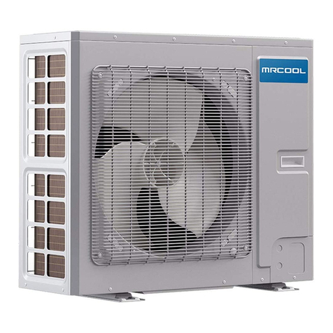
MrCool U-match MDUO1836 User manual

1
DC Inverter U-match Series for R410A
Unitary Split Air Conditioner SERVICE
MANUAL
Capacity: 24kBtu/h~60kBtu/h
Rate Frequency: 60Hz
Operation Range:
Cooling: 5°F(-15°C)~129.2℉(54℃)
Heating: -22°F (-30°C)~75.2°F (24°C)

Safety Notice
Before using the air conditioner, please first read the instruction manual.
Before installing the air conditioner, please first read the instruction manual.
Before repairing the air conditioner, please first read the technical service manual.

CONTENTS
Safety Notice on Maintenance.................................................................................................................. 1
Safety Notice on Operation........................................................................................................................2
1. Product Introduction............................................................................................................................... 3
1.1 Lists of Units......................................................................................................................................................... 3
1.2 Electrical Parameters.......................................................................................................................................... 5
2. Control........................................................................................................................................................ 6
2.1 Operation Mode....................................................................................................................................................6
2.2 Control Mode........................................................................................................................................................ 8
2.3 Functions.............................................................................................................................................................10
3. Troubleshooting..................................................................................................................................... 14
3.1 Wiring Diagrams.................................................................................................................................................14
3.2 PCB Layout........................................................................................................................................................17
3.3 Error Code...........................................................................................................................................................26
3.4 Troubleshooting................................................................................................................................................27
3.5 Failures Not Caused by Errors........................................................................................................................ 27
4. Maintenance............................................................................................................................................ 55
4.1 System Diagram.................................................................................................................................................55
4.2 Connection Pipe Vacuum Pumping................................................................................................................ 55
4.3 Refrigerant Charging.........................................................................................................................................57
4.4 Maintenance of Major Components................................................................................................................59
4.5 Removal of Major Components.......................................................................................................................69
4.6 Explosive View and Lists of Parts................................................................................................................. 103
Appendices................................................................................................................................................109
1. Resistance/Temperature Lists of Temperature Sensors...........................................................109
1.1 Voltage List of 15 kΩ Temperature Sensors (including ODU and IDU temperature sensors).............109
1.2 Voltage List of 20 kΩ Pipeline Temperature Sensors (including temperature sensors for defroster, IDU
and ODU pipes)...................................................................................................................................................... 111
1.3 Voltage List of 50 kΩ Discharge Temperature Sensors (including discharge air temperature sensor)
...................................................................................................................................................................................113
2. Temperature/Pressure List of Refrigerant.....................................................................................116
3. Refrigerant Notice/Concentration................................................................................................... 116
4. Operation Tools....................................................................................................................................116

DC Inverter U-match Series for R410A Unitary Split Air Conditioner
1
Safety Notice on Maintenance
PROHIBITED:
(1) Do not pierce or burn.
(2) Please note that refrigerant may be odorless.
(3) The appliance shall be stored in a room without continuously operating ignition sources (For example: open
flames, an operating gas appliance or an operating electric heater).
(4) Indoor unit adopts special joints that can’t be detached. The installation method is the same with the
common joints. However, because the joint can’t be detached, if it is badly connected and causes leakage,
it needs to be cut and replaced by a new one through welding.
(5) Using unsuitable parts or tools may lead to electric shock or fire hazard.
(6) If refrigerant leaks during maintenance, please ventilate the room immediately. Heavy leakage may lead to
breathing difficulty, severe injury or death.
(7) Disconnect power before disassembling the appliance for maintenance.
(8) The appliance should be maintained and cared by authorized technical personnel with necessary
qualifications.
WARNING:
(1) If the working place is more than 2m's high, please wear a safety helmet, gloves and a safety belt.
(2) Never mix any other substances except the specified refrigerant into the refrigerant circuit.
(3) When re-locating the appliance, check whether the new location is strong enough to withstand the weight of
the appliance.
(4) If there is refrigerant leak, please fix the leak before charging in the refrigerant. After refrigerant is charged,
check for refrigerant leaks. If you cannot spot the leak, stop the maintenance work. Please evacuate the
system and close the service valve to prevent refrigerant leaking into the room.
(5) Prepare suitable tools and protectors.
(6) If you need to carry out maintenance or check the electric circuit without cutting off the power, please be
careful not to touch the electrical parts.
NOTICE:
(1) If the appliance is maintained at a humid place, it should be grounded to avoid electric shock.
(2) Never repair the unit with wet hands. Operating the unit with wet hands may lead to electric shock.
(3) If the unit is not correctly grounded, please check and fix it.
(4) Before cleaning the unit, please disconnect power to prevent the inner fan from starting up and running at

Universal Service Manual
2
high speed; Otherwise personal injury may occur.
(5) Measure the insulation resistance after maintenance. The resistance must be 1M or higher. Bad insulation
may lead to electric shock.
(6) Welding and cutting work must be done in a well-ventilated place.
(7) Gas appliances, heaters and other fire sources should be kept away from the installation and maintenance
site.
(8) Maintenance should be done according to suggestions of the manufacturer.
(9) Maintenance should be done only after the refrigerant is completely reclaimed from the unit.
OBSERVED:
(1) After the maintenance work is done, check the drainage of indoor unit.
(2) Do not tilt the unit, otherwise, water may spill out from the unit and make the floor and furniture wet.
(3) Disassembly of the unit, handling of the refrigerant, oil and accessories should all be done according to
applicable local rules and regulations.
Safety Notice on Operation
PROHIBITED:
(1) Never try to modify the unit, otherwise, it may cause electric shock, overheat or fire hazard.
(2) If the power cord or conducting wires are scratched, please replace them.
(3) Never use connected or extended power cord or share the power socket with other appliances.
(4) Prepare a specialized power circuit for the appliance.
WARNING:
(1) If the power plug is dirty, please clean it before inserting it to the power socket. If the power plug is loose,
please tighten it up.
(2) Do not damage the power cord. A damaged or refitted power cord may lead to electric shock or fire hazard.
(3) Check frequently whether the appliance is in good condition.
NOTICE:
(1) After changing the batteries of remote control, please discard them to avoid being swallowed by children.
(2) When the unit is working, do not remove the fan cover.
(3) Do not use organic solvents to wipe the controller operating panel.
(4) Before cleaning the unit, cut off the power supply.

MRCOOL Universal Service Manual
3
1. Product Introduction
1.1 Lists of Units
1.1.1 List of Outdoor Units
Model
Power Supply
Appearance
V/Ph/Hz
MDUO1836
208/230V-1Ph-60Hz
MDUO1860
208/230V-1Ph-60Hz

MRCOOL Universal Service Manual
4
1.1.2 List of Indoor Units
Model
Cooling/Heating
Capacity (Btu/h)
Power Supply
Appearance
V/Ph/Hz
Airhandler
MDUI18024
24000/24000
208/230V-1Ph-60Hz
Airhandler
MDUI18036
36000/36000
208/230V-1Ph-60Hz
Airhandler
MDUI18048
48000/48000
208/230V-1Ph-60Hz
Airhandler
MDUI18060
54000/54000
208/230V-1Ph-60Hz
Note: 1 Ton =12000Btu/h = 3.517kW

MRCOOL Universal Service Manual
5
1.2 Electrical Parameters
Model
Power supply
Circuit breaker capacity
V/Ph/Hz
A
MDUO1836
208/230V-1Ph-60Hz
35
MDUO1860
208/230V-1Ph-60Hz
45
Model
Power Supply
Fuse Capacity
Circuit Breaker Capacity
V/Ph/Hz
A
A
MDUO1824
208/230V-1Ph-60Hz
15
15
MDUO1836
208/230V-1Ph-60Hz
15
15
MDUO1848
208/230V-1Ph-60Hz
15
15
MDUO1860
208/230V-1Ph-60Hz
15
15

MRCOOL Universal Service Manual
6
2. Control
2.1 Operation Mode
2.1.1 Cooling Mode

MRCOOL Universal Service Manual
7
2.1.2 Heating Mode

MRCOOL Universal Service Manual
8
2.2 Control Mode
2.2.1 Based Control
2.2.1.1 Compressor Control
When cooling or heating mode is turned on, indoor fan will run for a while before the compressor starts.
Under different modes, the compressor can only be stopped after running for some time (special cases excluded).
This is to protect the compressor from frequent start or stop. Once the compressor is stopped, it must not be
restarted right away. Please wait for a few minutes.
2.2.1.2 EXV Control
When the unit is first started, the electronic expansion valve will reset control. During the process, the
expansion valve will produce rattling sound. When cooling or heating mode is turned on, the valve will be open at
a certain step before the compressor starts.
2.2.1.3 Outdoor Fan Control
This series air conditioner has two types of outdoor units: one with a single fan and the other with double
fans. The outdoor fan can run at the highest level 10 and the lowest level 1. By controlling the speed of outdoor
fan, the unit can achieve cooling at low temperature and heating at high temperature. In fan mode, outdoor fan
will not work.
2.2.1.4 4-way Valve Control
After heating mode is turned on for a while, 4-way valve will be energized to change the direction of
refrigerant flow so that the system can run in heating and the indoor unit will not blow cold air. Under other modes,
the valve will not be energized.
To avoid the 4-way valve from incorrectly changing directions, when the unit stops in heating, due to a
temperature point or other protection reasons, the 4-way valve will continue to function temporarily and lose
power after a while.
There must be adequate differential pressure for the 4-way valve to change directions.
2.2.2 Special Control
2.2.2.1 Defrosting Control
ODU defrosting control in heating: Defrosting will start when the temperature sensed by outdoor tube
temperature sensor reaches a preset value. During defrosting, the 4-way valve will switch to the cooling condition,

MRCOOL Universal Service Manual
9
and outdoor and indoor fan will both stop. When the temperature sensed by outdoor tube temperature sensor
reaches the preset value of defrosting stop, system will quit defrosting. The 4-way valve will switch back to the
heating condition, compressor and outdoor unit fan restart.
2.2.2.2 Oil Return Control
If the unit is running at low frequency for a long time, system will enable oil return control. This is to lead oil in
the pipeline back to the compressor so that the compressor will not be lack of oil. Generally, the oil return takes
about 5min. The compressor running frequency will be raised to the preset oil return frequency.
2.2.3 Protection Control
2.2.3.1 High Pressure Protection Control
System will enable high pressure protection control if the high pressure switch is detected open for
continuously a little time. Under high pressure protection, system will be shut down and display error code E1.
When high pressure protection occurs for the first time, system will restore operation if the high pressure
switch is detected to be reclosed for continuously a little time. When high pressure protection occurs for the
second time in a certain time period, system will not restore operation. You need to manually turn off the unit and
clear the error before restarting up the unit. (If high pressure protection occurs frequently, please send for
professional personnel to repair.)
2.2.3.2 Low Pressure Protection Control
System will enable low pressure protection control if the low pressure switch is detected open for
continuously a little time. Under low pressure protection, system will be shut down and display error code E3.
When low pressure protection occurs, system will restore operation if the low pressure switch is detected to be
reclosed within a few minutes after shutdown. If low pressure protection occurs for several times in a period of
time, system will not restore operation automatically. You need to manually turn off the unit before restarting up
the unit.
2.2.3.3 High Temperature Prevention Control
Under heating mode, system will enable high temperature prevention control if the temperature sensed by
indoor tube temperature sensor reaches a certain value. When high temperature prevention control is enabled,
outdoor fan will slow down.
2.2.3.4 Discharge High Temperature Protection Control
System will enable discharge temperature protection control if the discharge high temperature sensor is

MRCOOL Universal Service Manual
10
detected open for continuously a little time. Under discharge high temperature protection, system will be shut
down and display error code E4. When discharge high temperature protection occurs, system will restore
operation if the discharge high temperature sensor is detected to be reclosed within a few minutes after shutdown.
If discharge high temperature protection occurs for several times in a period of time, system will not restore
operation automatically. You need to manually turn off the unit before restarting up the unit.
2.3 Functions
2.3.1 Set Capacity Dial Code
Set the capacity of the outdoor unit through the four-digit dial codes of the outdoor unit main control board.
Specific dialing definition, the first digit dial code distinguishes the capacity.
Capacity
24K
36K
48K
60K
Dial Codes
2.3.2 Set Defrost Mode
The second digit dial code are selecting the defrost mode. The following table shows the 36K outdoor unit
dial code for example. Mode 1 is conventional defrost,mode 2 is suitable for defrosting in ultra-low temperature
environment.
Defrost mode
Outdoor unit dial code
Defrost mode 1
(Default)
Defrost mode 2
2.3.3 Set Operating Mode
The third digit dial code and the fourth digit dial code are selecting the operating mode. The following table
shows the 36K outdoor unit dial code for example. Standard mode is the conventional mode.

MRCOOL Universal Service Manual
11
By setting the Forcible mode dial codes of the condensing unit, the air conditioner can quickly increase the
capacity output and ensure reliable operation in a short time, so as to meet the user's demand for the indoor
temperature to quickly reach the set temperature.
Energy saving mode is achieved by setting the condensing unit operating mode to operate the air
conditioner within a small load range.
Operating mode
Outdoor unit dial code
Standard mode
(Default)
Forcible mode
Energy saving
mode
2.3.4 Set Indoor Fan Speed
Set the indoor fan speed through the four-digit dialing codes of the indoor main control board. The higher
level, the higher speed of the indoor unit fan.
Capacity
24K indoor unit dial code
36K indoor unit dial code
Level 1
(Default)
Level 2
Level 3
Capacity
48K indoor unit dial code
60K indoor unit dial code

MRCOOL Universal Service Manual
12
2.3.5 Forced Defrost Control
Press and hold "SW1" for about 5s to enter the first level menu of the debugging mode, the outdoor unit
mainboard LED displayer flashes. Under the first level menu, short press "SW1" to switch various functions. After
switching to "06", short press "SW2" or "SW3" to enter the forced defrosting mode, "ON" means open, "OF"
means close, and then short press "SW1" to save. During debugging, if no operation is performed within 10s, the
debugging mode interface will be exited.
2.3.6 Refrigerant Recovery Control
Press and hold "SW1" for about 5s to enter the first level menu of the debugging mode, the outdoor unit
mainboard LED displayer flashes. Under the first level menu, short press "SW1" to switch various functions. After
switching to "08", short press "SW2" or "SW3" to enter the refrigerant recovery control mode, "ON" means open,
"OF" means close. And then short press "SW1" to save. During debugging, if no operation is performed within
10s, the debugging mode interface will be exited.
2.3.7 Forced Operation Control
Press and hold "SW1" for about 5s to enter the first level menu of the debugging mode, the outdoor unit
mainboard LED displayer flashes. Under the first level menu, short press "SW1" to switch various functions. After
switching to "09", short press "SW2" or "SW3" to enter the forced operation control mode, "01" denotes that turn
on the forced operation cooling mode; "02" denotes that turn on the forced operation cooling mode; "OF"
Level 1
(Default)
Level 2
Level 3

MRCOOL Universal Service Manual
13
indicates that shut down the forced cooling / heating mode. And then short press "SW1" to save. During
debugging, if no operation is performed within 10s, the debugging mode interface will be exited.
2.3.8 Thermostat Functions
Thermostat model: XE70-00/E1, please refer to the thermostat instruction manual for all functions.

MRCOOL Universal Service Manual
14
3. Troubleshooting
3.1 Wiring Diagrams
The following electric diagram is for reference only. Please refer to diagram sticked on the unit as the latest
version.
3.1.1 Wiring Diagrams of ODUS
Model: MDUO1836

MRCOOL Universal Service Manual
15
Model: MDUO1860

MRCOOL Universal Service Manual
16
3.1.2 Wiring Diagrams of IDUs
Model: MDUO18024036
Model: MDUO18048060

MRCOOL Universal Service Manual
17
3.2 PCB Layout
3.2.1 Interface
Indoor unit:
Model: MDUI18024, MDUI18036, MDUI18048, MDUI18060,
Mainboard
No.
Printing
Interface
No.
Printing
Interface
1
AC-N(X2)
Neutral wire input
8
X9(G_SCAN)
Indoor motor check
2
AC-L (X1)
Live wire input
9
X14(OFAN-H-OUT)
AC motor high speed
output
3
CN3
Wired control
communication
interface
10
X11(OFAN-H-IN)
AC motor high speed
input
4
CN1
DC motor output
11
X8(OFAN-L-IN)
AC motor low speed
input
5
X7
Transformer Neutral
wire input
12
X6(OFAN-L-OUT)
AC motor low speed
output
6
X13
Transformer Live
wire input
13
X3(C)
Transformer Neutral
wire output
This manual suits for next models
7
Table of contents
Other MrCool Inverter manuals
Popular Inverter manuals by other brands

Apxteck
Apxteck AT?MG250 installation manual

Redback
Redback SH5000 installation manual

Go Power! Electric
Go Power! Electric GP-SW1500TS user manual

Northern Lights
Northern Lights NL1064D, NL1064T1, NL1064T2, NL1064H1, NL1066T, NL1066H1, NL1066H2, and... Operator's manual

Masspower
Masspower SUN-1000GTIL2-LCD user manual

Sincro
Sincro SK315 Series Use and maintenance manual

Cotek
Cotek S600 Series user manual

Growatt
Growatt MIN 2500TL-XH Installation & operation manual

Champion Power Equipment
Champion Power Equipment 500319-N owner's manual

Victron energy
Victron energy 48/3000/35-32 manual

BlueSun
BlueSun BSM8K-B user manual

SimpliPhi
SimpliPhi Outback AccESS installation manual