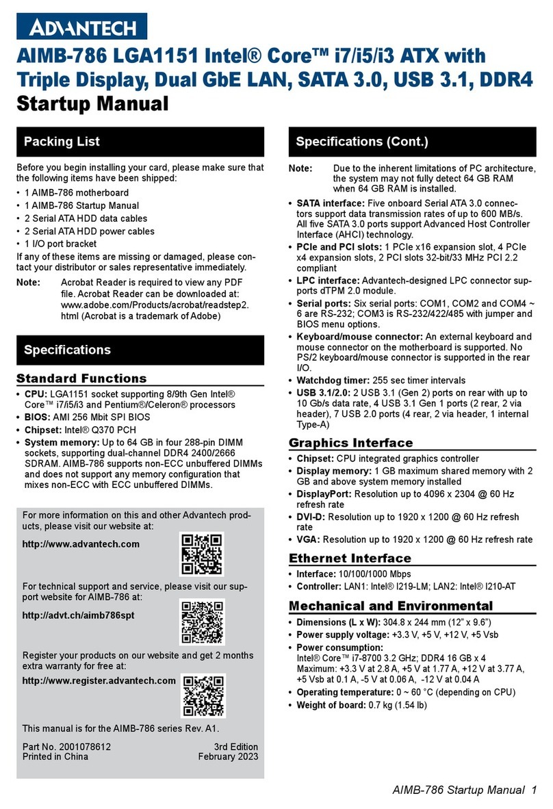
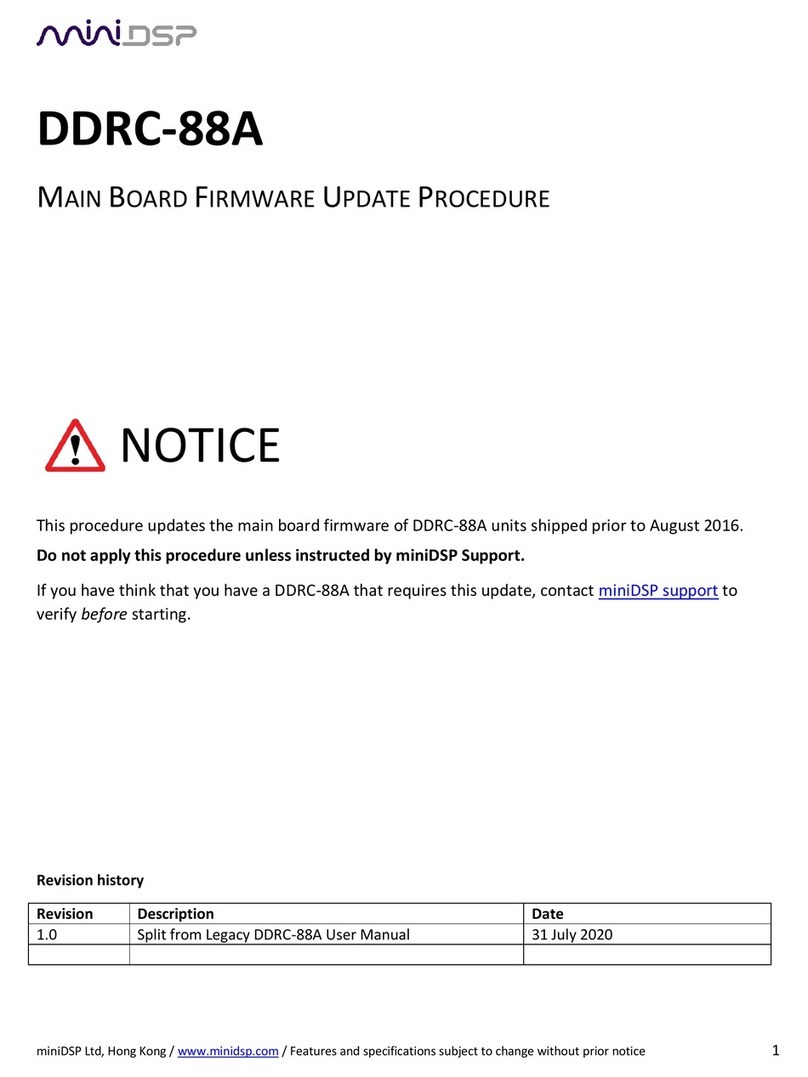
Advanced AXIS AX AV-VBM Owner's manual

www.advancedco.com
Audio Panels
AV-VBM Audio Panel w/Microphone and
AV-VB Distributed Audio Booster
Installation, Operation & Programming Manual

www.advancedco.com
2
Table of Contents Page
1INTRODUCTION / OVERVIEW............................................................................................................................4
1.1PRODUCT DESCRIPTION..................................................................................................................................4
1.2GENERAL INSTALLATION NOTES .....................................................................................................................7
1.3FCC ..............................................................................................................................................................7
1.3.1Emissions.................................................................................................................................................7
2INSTALLATION....................................................................................................................................................8
2.1MOUNTING .....................................................................................................................................................8
3AV-VBM AND AV-VB MODULES......................................................................................................................10
3.1AX-PSU-6 POWER SUPPLY CHARGER..........................................................................................................10
3.1.1AX-PSU-6 AC Wiring .............................................................................................................................10
3.1.2AX-PSU-6 Battery Circuit Wiring............................................................................................................11
3.1.3AX-PSU-6 Additional Wiring ..................................................................................................................11
3.1.4AX-PSU-6 LEDs.....................................................................................................................................12
3.1.5AX-PSU-6 Jumper..................................................................................................................................12
3.2AV-AMP-80 AUDIO AMPLIFIER MODULE.......................................................................................................13
3.2.1AV-AMP-80 Wiring .................................................................................................................................14
3.2.1.1PBUS (485) AV-AMP-80 Wiring ...................................................................................................................15
3.2.2AV-AMP-80 LEDs ..................................................................................................................................16
3.2.3AV-AMP-80 Amplifier Backup Programming .........................................................................................16
3.2.4Microphone Wiring (AV-VBM only) ........................................................................................................17
3.2.5Optional AV-ZS Audio Zone Splitter Module .........................................................................................18
3.2.5.1AV-ZS Mounting ...........................................................................................................................................18
3.2.5.2AV-ZS Wiring................................................................................................................................................19
3.2.5.2.1AV-ZS Speaker Circuit Activation ............................................................................................................20
3.2.5.3Optional AV-ZS-CM AV Splitter Switch Module............................................................................................21
3.3AV-SM SWITCH/LED MODULE (AV-VBM ONLY)...........................................................................................22
3.3.1AV-SM Switch/LED Operation ...............................................................................................................23
3.4OPTIONAL AV-RMIC ALL-CALL REMOTE MICROPHONE ................................................................................23
4RECOMMENDED CABLE ROUTING................................................................................................................27
5AV-VBM AND AV-VB BATTERY CALCULATIONS .........................................................................................28
6AV-AMP-80 AMPLIFIER AUDIO MESSAGE PROGRAMMING.......................................................................29
6.1INSTALLING THE AXISAX AV-AMP AUDIO MESSAGE PROGRAMMING TOOL .......................................................29
6.2LAUNCHING THE AXISAX AV-AMP AUDIO MESSAGE PROGRAMMING TOOL.....................................................29
6.2.1File Menu ...............................................................................................................................................30
6.2.2Amplifier Group ......................................................................................................................................30
6.2.2.1Add AV-AMP ................................................................................................................................................30
6.2.3Product View (Description) ....................................................................................................................31
6.2.3.1Interpreting the Product Selected Message View Headers ..........................................................................31
6.2.3.1.1Message ..................................................................................................................................................31
6.2.3.1.2Audio Section 1 – Leading Tone/Message ..............................................................................................31
6.2.3.1.3Audio Section 2 – Main Tone/Message ...................................................................................................32
6.2.3.1.4Audio Section 3 – Trailing Tone/Message ...............................................................................................32
6.2.4Amplifier Tools Properties......................................................................................................................32
6.2.5Adding Audio Messages ........................................................................................................................32
6.2.5.1NPFA 72 (2013 Edition) Message Requirement...........................................................................................35
6.2.5.1.1Example of an NFPA 72 Programmed Message .....................................................................................35
6.2.6Remove Audio Messages ......................................................................................................................35
6.2.7Moving Messages Up and Down ...........................................................................................................36
6.2.8Playback of a Message..........................................................................................................................36
6.2.9Importing Audio Files .............................................................................................................................37
6.2.10Uploading Audio Messages...............................................................................................................38
6.2.11Canceling an Upload .........................................................................................................................38
6.3TYPICAL AV-VB AND AV-VBM APPLICATIONS..............................................................................................39
6.3.1AV-VB Interfaced to a Listed (Host) Audio EVAC System (Synchronized Messages/Tones)...............39

www.advancedco.com
www.advancedco.com 3
6.3.2AV-VB Interfaced to a Listed (Host) EVAC System (Non Synchronized Independent Messages/Tones)
40
6.3.3AV-VBM Interfaced to a Listed (Host) Fire Alarm Control Panel...........................................................41
6.3.4AV-VBM Interfaced to a Listed (Host) Fire Alarm Control Panel and the AV-VB Distributed Audio
Booster (Synchronized Messages/Tones)..........................................................................................................42
6.3.5AV-VBM Interfaced to a Listed (Host) Fire Alarm Control Panel and the AV-VB Distributed Audio
Booster Independent Messages (Non Synchronized Messages/Tones) ...........................................................43
7SPECIFICATIONS..............................................................................................................................................44
8ORDERING INFORMATION..............................................................................................................................45

www.advancedco.com
4
1 Introduction / Overview
1.1 Product Description
This manual covers the installation and operation of the AV-VBM Audio Panel w/Microphone and AV-VB Distributed
Audio Booster. The AV-VBM and AV-VB consist of an audio amplifier module containing; two (2) 40 watt amplifiers
(controlled together, or one dedicated as a backup amplifier), a digital message/tone generator, supervision
circuitry, a power supply charger and an enclosure (see figure 1). In addition, the AV-VBM includes an AV-MIC
microphone and AV-SM switch/LED module for manual control of messages and live voice communication (see
figure 2). AV-VB distributed audio booster can also be configured for use in AxisAX PBUS (485) amplifier
installations. When used as a PBUS (485) amplifier, each AV-VB booster can accommodate 16 prioritized
messages and operate with other amplifiers in “PerfectSync”.
Note: Messages played on the AV-VBM audio panel w/microphone or on the AV-VB distributed audio
booster are broadcasted via two electrically independent amplifiers (speaker circuits) playing
simultaneously. In addition, the AV-VB distributed audio booster can be utilized in an AxisAX PBUS (RS485)
audio installation, supporting sixteen (16) prioritized messages and Advanced “PerfectSync”
synchronization.
Both the AV-VBM audio panel w/microphone and AV-VB distributed audio booster are designed to provide audio
signaling during an emergency situation (alarm, alerts, warnings, mass notification, etc.). In addition, the AV-VBM
can also provide live voice communication override. Both the AV-VBM and AV-VB are designed for use in
conjunction with an AxisAX intelligent fire alarm control panel or any other ANSI/UL864 Listed fire alarm control
panel. The AV-VB distributed audio booster can also be utilized in AxisAX intelligent fire alarm control panel PBUS
(RS485) amplifier installations.

www.advancedco.com
www.advancedco.com 5
OUT- OUT+ IN- IN+
AMP1
OUT- OUT+ IN- IN+
AMP2
+24V GND +2 4V GND
POWER
B A B A
RS485
AMP-1
A+ A- B- B+
AMP-2
A+ A- B- B+
INPUTS
IN1 GND IN2 GND IN 3 GND
TROUBLE
COM NO NC
Figure 1 – AV-VBM and AV-VB Backbox
AV-AMP-80
Audio Amplifier Module
AX-PSU-6
Power Supply Charger

www.advancedco.com
6
The AV-VBM audio panel w/microphone and AV-VB distributed audio booster are designed to be powered from 120
– 240VAC at 50/60 Hz. Each unit incorporates two (2) electrically independent Class A or B amplifier speaker
circuits, rated 40 Watts per amplifier circuit maximum. Speaker circuit requirements are 25 VRMS.
Note: For 70 VRMS installations refer to Advanced’ AV-V70 Universal Audio Converter Installation &
Operational Panel PN: 682-044.
The AV-SM switch/LED module of the AV-VBM audio panel w/microphone provides a power LED, two trouble LEDs
(power supply charger and audio amplifier) visible with the outer door closed and three toggle switches (play
message one, play message two and push down/hold for all-call). In addition, the AV-SM switch/LED module
provides terminals for host fire alarm control panel monitoring interface. An optional AV-ZS-CM AV splitter switch
module is available for installations utilizing the Advanced’ optional AV-ZS amplifier speaker circuit zone splitter
module.
Figure 2 – AV-VBM Inner Door Shown with Microphone and AV-SM (Switch/LED Module)
(Also Shown with Optional AV-ZS-CM [AV Splitter Switch Module])
AV-MIC
(Microphone Assembly)
AV-SM (Switch/LED Module)
(Includes Power LED, Trouble LEDs,
Message Switches and All Call Switch)
Optional AV-ZS-CM
(AV Splitter Switch Module)

www.advancedco.com
www.advancedco.com 7
1.2 General Installation Notes
WARNING: Disconnect all sources of power (AC and
battery) before installing/removing circuit cards or
servicing the AV-VBM audio panel w/microphone or AV-
VB distributed audio booster.
USE an anti-static wrist strap whenever
handling circuit cards.
STORE circuit cards in static
suppressive packaging.
ENVIRONMENT: INSTALL the equipment in a clean,
dry environment.
The equipment meets the requirements for operation at
32°F - 120°F (0°C - 49°C) and relative humidity of 85%
RH. However, standby battery life is drastically reduced
at higher temperatures. The recommended room
temperature for installation is 60°F - 86°F (15°C - 27°C).
WIRING: CHECK that the installation wire sizes are
adequate to deliver the required load current and
maintain compatibility with the specific device operating
voltages.
A secure dedicated ground connection is
required. Although no system is immune to
the effects of lightning strikes, a secure
ground connection will reduce susceptibility.
The use of overhead or outside aerial wiring is
not recommended.
1.3 FCC
1.3.1 Emissions
WARNING: This equipment generates, uses, and can radiate radio frequency energy. If it is not installed in
accordance with the instructions in this manual, it may cause interference to radio communications.
This equipment has been tested and found to be in compliance with the limits for a Class A computing device
pursuant to Subpart B of Part 15 of FCC Rules, which is designed to provide reasonable protection against such
interference when operated in a commercial environment. Operation of this equipment in a residential area is likely
to cause interference in which case, the user will be required to correct the interference at their expense.
ATTENTION
OBSERVE PRECAUTIONS
FOR HANDLING
ELECTROSTATIC
SENSITIVE DEVICES
Must be
Grounded

www.advancedco.com
8
2 Installation
Mount the AV-VBM and/or AV-VB enclosure in a clean, dry, vibration-free area where extreme temperatures are not
encountered. The area should be readily accessible with sufficient room to easily install, utilize and maintain the
product. Determine the number of conductors required for control and supervision to be installed. Sufficient
knockouts (4 double 1 ¾” or 7/8 [two top and two bottom] and 3 single 7/8” [top]) are provided for wiring
convenience. Select the appropriate knockout(s) and pull the required conductors into the back box, separating
power limited from non-power limited conductors – refer to the recommended cable routing diagram Section 4. All
wiring should be in accordance with National Electric Code (NEC), State and Local codes.
2.1 Mounting
The AV-VBM audio panel w/microphone and AV-VB distributed audio booster enclosures are designed for either
surface or semi-flush mounting (~ ¾ inch flange around back box).
There are five (5) mounting holes
located on the back wall of the AV-
VBM and/or AV-VB back box (see
opposite).
The top center mounting hole is
keyed for ease of mounting. Place
the back box on the wall and mark
the top center keyed mounting
hole. Drill the marked location and
partially install the mounting screw
in the wall.
Hang the cabinet on the center
mounting screw. Level the cabinet,
and mark and drill the remaining
four (4) mounting holes (two on the
top, two on the bottom).
Insert all screws and firmly tighten.
CAUTION: If drilling while mounting the AV-VBM and/or AV-VB enclosure is going to make any metal filings or
other PC board contaminants, remove all circuit cards from the enclosure.
To remove the circuit cards from the AV-VBM and/or AV-VB enclosure;
1. AV-AMP-80: Unplug terminal blocks containing internal wiring (AV-VBM only, unplug the 6-way ribbon
cable running from the AV-AMP-80 [PL2] to the AV-MIC microphone assembly), remove the three (3)
screws holding the AV-AMP-80 mounting plate to the enclosure, slide AV-AMP-80 mounting plate out from
under the back box mounting tabs located on the right side of the audio amplifier mounting plate (see figure
3).
2. AX-PSU-6: Remove the four (4) screws holding the AX-PSU-6 power supply charger to the enclosure (see
figure 3).
Failure to tighten screws will defeat the protection circuitry designed to protect the modules/cards from
damage due to lightning and static electricity.

www.advancedco.com
www.advancedco.com 9
OUT- OUT+ IN- IN+
AMP1
OUT-OUT+ IN- IN+
AMP2
+24V GND +24V GND
POWER
B A B A
RS485
AMP-1
A+ A- B- B+
AMP-2
A+ A- B- B+
INPUTS
IN1 GND IN2 GND IN3 GND
TROUBLE
COM NO NC
Figure 3 – AV-VBM and AV-VB Module Removal
AV-MIC
6-way Ribbon Cable
(AV-VBM Only)
Mounting Plate Screws
Mounting Plate Screws
Mounting Plate Screw

www.advancedco.com
10
3 AV-VBM and AV-VB Modules
3.1 AX-PSU-6 Power Supply Charger
The AX-PSU-6 is the power supply and charger for the AV-VBM audio panel
w/microphone and AV-VB distributed audio booster.
3.1.1 AX-PSU-6 AC Wiring
AC Input
120 VAC 15 Amp Branch Circuit
#14 or #12 AWG (Refer to NEC)
Non-Power Limited
Fuse
5A, 250VAC Ceramic, Time Delay (size 5x20mm)
(Advanced part number 620-003, Bussmann S505-5-R,
Littelfuse 0215005.XP)
Over-current protection for this circuit must comply with
Article 760 of the National Electrical Code (NEC) and/or
local codes. 15A Branch Circuit.
The AX-PSU-6 must be connected to a
solid earth ground. Use #14 AWG (2.00
mm2) or larger wire with 600 volt
insulation rating.
The AX-PSU-6 provides a maximum of 6 Amps for powering
the AV-AMP-80 audio amplifier module and charging batteries
to meet installation backup requirements.
AX-PSU-6 Ratings
120-240 VAC (3A) 50/60Hz
98 VAC Brown-out
24 VDC, 4.5 Amp (Power Limited)
1.5 Amp maximum charge capacity
o45 Ah batteries maximum
oDeducted from overall 6 Amp power
Must be
earthed
N
L (HOT/LOAD)
(NEUTRAL)
(EARTH GROUND)
AC Input
15A Branch Circuit
#14 or #12 AWG
FUSE

www.advancedco.com
www.advancedco.com 11
3.1.2 AX-PSU-6 Battery Circuit Wiring
AX-PSU-6 Battery Charger
Charger current 1.5A (Maximum 45Ah).
Supervised, Non-Power Limited.
Charging voltage 27.4 VDC typical.
Charging temperature compensated.
Start the power supply charger on AC power first then
connect the batteries.
If AC power is not available the power supply charger
can be started directly from the batteries. Connect
batteries and press the “START FROM BATTERY”
push button.
The battery charger provides deep discharge
protection. Battery power will be disconnected when
voltage falls below 19V (nominal). If the batteries are
disconnected, the charger output is turned off.
The internal series resistance of the batteries is
continuously checked. If the internal series resistance
increases above 0.8Ωthen the power supply charger
will indicate a trouble condition.
3.1.3 AX-PSU-6 Additional Wiring
The AX-PSU-6 24 VDC power output is prewired to the
AV-AMP-80 audio amplifier module in both the AV-VBM
and AV-VB panels. The trouble/fault relay contact is
prewired in the AV-VBM to the AV-SM switch/LED
module. In the AV-VB the trouble/fault relay contact
must be monitored by the host fire alarm control panel.
The trouble relay contact is a fail-safe relay which
transfers on loss of power or any other power supply
charger trouble condition.
Note: The power supply trouble/fault relay contact,
in addition to the trouble relay contact, located on
the AV-AMP-80 audio amplifier module, are prewired
in the AV-VBM panel to the AV-SM switch/LED
module. These contacts located in both the AV-VBM
and AV-VB must be monitored by the host fire alarm
control panel to maintain proper supervision of the
AV-VBM audio panel w/microphone and AV-VB
distributed audio booster. If the AV-VB is utilized as
a PBUS (485) amplifier the AX-PSU-6 power supply
trouble/fault relay contact gets wired to input 1 of
the associated AV-AMP-80.

www.advancedco.com
12
3.1.4 AX-PSU-6 LEDs
There are seven (7) onboard LEDs associated with the
AX-PSU-6. Refer to the opposite diagram and list below
for LED descriptions and purpose.
1. Earth Fault: Illuminates on ground fault (within
10 seconds).
2. Heart Beat: Flashes to indicate proper
microprocessor operation.
3. Battery Connect (BAT CON): Illuminates on AC
failure when batteries are powering the supply.
4. Battery Low (BAT LOW): Illuminates when
batteries have a high internal resistance [battery
cell failure] (within 120 seconds).
5. Battery O/C (BAT O/C): Illuminates when
batteries are disconnected (within 40 seconds).
6. Charger Fault (CHGR FLT): Illuminates on
charger output failure (within 90 seconds).
7. Mains Fault (MAINS FLT): Flashes on AC
supply failure (within 20 seconds).
3.1.5 AX-PSU-6 Jumper
Jumper 5-6 must always be installed to allow for proper
battery charging. Battery charging can support up to 45
Ah batteries maximum.
Note: On the AV-VB, jumper switches 1-2 (power supply Trouble LED drive) and 3-4 (power supply ON LED
drive) are utilized as the LED status drivers for the LED indicators located on the front of the AV-VB
enclosure
2
4
6
8
1
3
5
7
DO Not
Remove
Jum
p
e
r

www.advancedco.com
www.advancedco.com 13
3.2 AV-AMP-80 Audio Amplifier Module
The AV-AMP-80 audio amplifier module provides the digital audio capabilities (live voice communications with AV-
VBM) of the AV-VBM audio panel w/microphone and AV-VB distributed audio booster and requires 24 VDC nominal
power from the AX-PSU-6 (see figure 4).
The AV-AMP-80 contains two (2) electrically independent Class “A” or “B”, 40 Watt @ 25 Vrms, amplifiers (Audio
Notification Appliance Circuits - ANACs) [controlled together or amplifier two dedicated as a backup to amplifier
one]. Each amplifier (audio notification appliance circuit) is activated whenever one of the AV-AMP-80 trigger inputs
is activated (trigger input activation on AV-VBM is via the AV-SM switch/LED module).
In addition to providing the two (2) electrically independent amplifiers (audio notification appliance circuits), the AV-
AMP-80 has an integral two (2) programmable, flash-based, digital message/tone generator. Messages are freely
programmable and can be tailored to meet specific installation requirements.
There are three (3) trigger inputs on the AV-AMP-80 (two of these, trigger input 1 and trigger input 2, are prewired
on the AV-VBM to the AV-SM switch/LED module) for activating the audio amplifiers; trigger input 1, trigger input 2
and trigger input 3.
Trigger input 1 when activated, not only turns on both amplifiers (audio notification appliance circuits) it also
activates programmed message/tone #1 and plays this message over the audio notification appliance
circuits. Trigger input 1 has a higher priority than trigger input 2. If both trigger inputs are active at the same
time, programmed message/tone #1 will be broadcasted.
Trigger input 2 when activated plays message/tone #2 on both amplifiers (audio notification appliance
circuits).
Trigger input 3 sets the AV-VBM audio panel w/microphone and/or AV-VB distributed audio booster to
“booster mode”, this allows any external audio signal ( 25vrms) to be broadcasted out of one or both of the
AV-AMP-80 amplifiers (based on wiring). This trigger input has the highest priority, if both trigger input 1
and 2 are active during a trigger input 3 activation, amplifiers will broadcast the external audio signal. This is
how live voice communications are broadcasted through the AV-VB distributed audio booster amplifiers. By
activating trigger input 3 on the AV-AMP-80 of the AV-VB distributed audio booster, microphone
communications from an AxisAX integrated audio intelligent fire alarm control panel, an AV-VBM audio panel
w/microphone or a host EVAC system can be rebroadcasted out of the AV-VB distributed audio booster
amplifiers.
Designed into the AV-AMP-80 is a dedicated Form “C” trouble relay contact which transfers on any amplifier and/or
audio notification appliance circuit trouble/failure. This trouble/fault relay contact is prewired in the AV-VBM to the
AV-SM switch/LED module. In the AV-VB the trouble/fault relay contact must be monitored by the host fire alarm
control panel.
Note: The trouble relay contact, in addition to the power supply charger trouble/fault relay contact, located
on the AX-PSU-6 power supply charger, are prewired in the AV-VBM panel to the AV-SM switch/LED
module. These contacts located in both the AV-VBM and AV-VB must be monitored by the host fire alarm
control panel to maintain proper supervision of the AV-VBM audio panel w/microphone and AV-VB
distributed audio booster. If the AV-VB is utilized as a PBUS (485) amplifier trouble/fault monitoring is
accomplished by the AX-CTL base card via the PBUS (485) connection.

www.advancedco.com
14
3.2.1 AV-AMP-80 Wiring
OUT- OUT+ IN- IN+
AMP1
OUT- OUT+ IN- IN+
AMP2
+24V GND +24V GND
POWER
B A B A
RS485
AMP-1
A+ A- B- B+
AMP-2
A+ A- B- B+
INPUTS
IN1 GND IN2 GND IN3 GND
TROUBLE
COM NO NC
TX
HB
AMP1
AMP2
40V
USB
4.7K EOL
Form “C”
Trouble Contact
AMP 1
Audio Input
AMP 2
Audio Input
24VDC
In / Out
Not Used
Class “A” Wiring
Trigger Input 1
Microphone Input
(Prewired to AV-MIC on AV-VBM)
(MIC Supervision Jumper on AV-VB)
Status
LEDs
Trigger Input 2
Trigger Input 3
S SSS
S SSS
Class “B” Wiring
(Prewired to AV-SM
Switch/LED on AV-VBM) (Prewired to AX-PSU-6 Power
Supply Charger. In addition,
prewired to AV-SM on AV-VBM)
Figure 4 – AV-AMP-80 Wiring

www.advancedco.com
www.advancedco.com 15
3.2.1.1 PBUS (485) AV-AMP-80 Wiring
As previously indicated, AV-VB distributed audio boosters can also be configured for use in AxisAX PBUS (485)
amplifier installations. When an AV-VB is utilized in this configuration, the amplifier is wired as a PBUS (485) floor
(area) amplifier. As a PBUS (485) floor (area) amplifier the amplifier is connected an AxisAX fire alarm control
panel’s AX-CTL base card (PBUS) and all control / operation is done via the associated base card. In addition to
wiring to an AX-CTL base card, the amplifier will also monitor the associated AX-PSU-6 power supply and report its
status to the AX-CTL base card (see figure 5).
Note: For additional information regarding AV-VB distributed audio booster PBUS (RS485) use, refer to the
associated AxisAX audio fire alarm control panel manual.
OUT- OUT+ IN- IN+
AMP1
OUT- OUT+ IN- IN+
AMP2
+24V GND +24V GND
POWER
B A B A
RS485
AMP-1
A+ A- B- B+
AMP-2
A+ A- B- B+
INPUTS
IN1 GND IN2 GND IN3 GND
TROUBLE
COM NO NC
TX
HB
AMP1
AMP2
40V
USB
4.7K EOL Microphone Bus Input
To Dedicated AX-PSU-6
24VDC (terminals 0V and +V0)
To AX-CTL Base Card
PBUS (RS-485)
Class B Only
Class “A” Wiring
Class “B” Wiring
Installed Microphone Supervision Plug
To Dedicated AX-PSU-6
Trouble Relay Contact
(terminals COM and NO)
S SSS
S SSS
Microphone Bus EOL (end-of-line) or
to next AV-AMP-80 Area Amplifier
PBUS (RS485)
Address Switch
To Next PBUS
(RS-485) Module
Two (2) Class A or B Area Amplifier Circuits (circuits
activate in tandem)
Note: In the AV-AMP v1.1.1 or higher, amplifier
message programming tool, amplifier 2 can be
configured as a backup to amplifier 1.
Figure 5 – PBUS AV-AMP-80 Floor (area) Wiring

www.advancedco.com
16
3.2.2 AV-AMP-80 LEDs
There are six (6) onboard LEDs associated with the AV-AMP-80 (see figure 6).
1. Transmit (TX): Flashes when sending data via USB or RS485 port.
2. Heart Beat (HB): Flashes to indicate proper microprocessor operation.
3. Amplifier 1 (AMP 1): On steady when amplifier 1 is active. Flashes on amplifier 1 trouble or open/short
circuit on amplifier 1 speaker circuit.
4. Amplifier 2 (AMP 2): On steady when amplifier 2 is active. Flashes on amplifier 2 trouble or open/short
circuit on amplifier 2 speaker circuit.
5. 40V: On steady when amplifiers are active, flashes during amplifier supervision test.
6. USB: On steady when amplifier message is being programmed (USB port connected).
3.2.3 AV-AMP-80 Amplifier Backup Programming
As previously discussed, both amplifiers (AMP 1 and AMP 2) of the AV-AMP-80 amplifier are controlled together.
However, based on installation or local code requirements, amplifier 2 (AMP 2) can be configured as a backup
amplifier for amplifier 1 (AMP 1).
Configuring amplifier 2 as a backup amplifier is done in the AxisAX AV-AMP audio message programming tool,
simply check the associated “Backup Mode Enabled” box within the Properties (see figure 7).
Figure 6 – AV-AMP-80 Status LED’s
Figure 7 – AV-AMP-80 Amplifier Backup Programming

www.advancedco.com
www.advancedco.com 17
3.2.4 Microphone Wiring (AV-VBM only)
To allow for live voice communications, the AV-VBM audio panel w/microphone has a 6-way ribbon cable that is
prewired from an AV-MIC microphone assembly, located on the AV-VBM inner door, to the AV-AMP-80 audio
amplifier module input connector PL2 (see figure 8). This connection not only allows for live voice communications,
but also monitors the AV-VBM microphone for both placement and open microphone condition.
Figure 8 – AV-MIC Microphone Assembly Wiring

www.advancedco.com
18
3.2.5 Optional AV-ZS Audio Zone Splitter Module
The AV-AMP-80 audio amplifier module is capable of accommodating an optional Advanced AV-ZS audio zone
splitter module.
The AV-ZS audio zone splitter module is designed to take one or both AV-AMP-80 amplifiers (audio notification
appliance circuits) and split these into additional audio notification appliance circuits, each capable of delivering 20
Watts per circuit. If splitting two (2) AV-AMP-80 amplifiers (audio notification appliance circuits), each amplifier is
split into two (2) audio notification appliance circuits. If splitting one AV-AMP-80 amplifier (audio notification
appliance circuit), the amplifier is split into four (4) audio notification appliance circuits.
Note: The AV-ZS audio zone splitter module can only be installed in AV-VBM and AV-VB enclosures
manufactured after August of 2014.
3.2.5.1 AV-ZS Mounting
The AV-ZS audio zone splitter module is supplied with three (3) metal hexagon spacers and one (1) nylon spacer.
Remove the three (3) upper screws securing the AV-AMP-80 module to its mounting plate and install the three (3)
provided metal hexagon spacers. Install the provided nylon spacer into the fourth mounting hole on the AV-ZS
module (see figure 9).
Mount the AV-ZS audio zone splitter module above the AV-AMP-80 audio amplifier module, to the three (3)
previously installed metal hexagon spacers and secure with the previously removed screws (see figure 9).
Failure to tighten screws will defeat the protection circuitry designed to protect the module from damage
due to lightning and static electricity.

www.advancedco.com
www.advancedco.com 19
3.2.5.2 AV-ZS Wiring
Wire 24 VDC (from AV-AMP-80 power output terminals) to the power input terminals of the AV-ZS audio zone
splitter module. Wire one or both AV-AMP-80 amplifiers (audio notification appliance circuits) to the Audio Input 1
and Audio Input 2 terminals of the AV-ZS module and set jumpers J6 and J7 to their appropriate position [1 audio
input or 2] (see figure 10).
Note: The AV-ZS audio zone splitter module includes a fail-safe trouble relay contact which opens on any
split audio notification appliance circuit trouble condition or on loss of 24 VDC input power. This trouble
relay contact must be monitored by the Host fire alarm control panel (see figure 10).
TX
HB
AMP1
AMP2
40V
USB
Nylon Spacer
Figure 9 – AV-ZS to AV-AMP-80 Mounting

www.advancedco.com
20
Note: For additional information regarding the installation and operation of the AV-ZS audio zone splitter
module, refer to AV-ZS Audio Zone Splitter Module Installation Instructions.
3.2.5.2.1 AV-ZS Speaker Circuit Activation
The AV-ZS audio zone splitter module speaker circuits are activated by switching the common (COM) of the Input
Zone Selection terminal block, through an activation relay contact back to the specific Input Zone Selection (Z1, Z2,
Z3, Z4) terminal block for the specific speaker circuit activation. In addition, the Input Zone Selection terminal block
incorporates an ALL input selection for activating all speaker circuits (see figure 11).
AUDIO INPUT 1
B+ B- A- A+
AUDIO INPUT 2
B+ B- A- A+
INPUT ZONE SELECTION
COM Z1 Z2 Z3 Z4 ALL
TROUBLE
COM N/O
A+ A- B- B+
ZONE 4
A+ A- B- B+
ZONE 3
A+ A- B- B+
ZONE 2
A+ A- B- B+
ZONE 1
+24
V
0
V
+24
V
0
V
O/C Z4
S/C Z4
O/C Z3
S/C Z3
O/C Z2
S/C Z2
O/C Z1
S/C Z1
CLASS
B A
CLASS
B A
CLASS
B A
CLASS
B A
J11 J10 J9 J5
J7 J6 J1
J2
J3
TROUBLE
POWER
LEDS
REMOTE
+24V
DC IN
1 AUDIO I/P
2 AUDIO I/PS
Figure 10 – Optional AV-ZS Audio Zone Splitter Module
Figure 11 – AV-ZS Speaker Circuit Activation
This manual suits for next models
1
Table of contents
Popular Computer Hardware manuals by other brands

Ovislink
Ovislink Wireless-G USB Dongle user manual

Diagnostic Associates
Diagnostic Associates DA-Dongle J2534 user manual
Texas Instruments
Texas Instruments TMS320C67X+ DSP reference guide

AMagic
AMagic ACC-ECU3 user manual
ETC
ETC 7123K1028-REPLC installation guide
Cowlacious Designs
Cowlacious Designs CAD-200 manual
