Advanced PSU EN54-4 User manual

www.advancedco.com
PSU EN54-4 Power Supplies

www.advancedco.com
2
Ordering:
Models, Sales Order Parts:
PSU
MXP-549 : 1.5A PSE in 7Ah enclosure
MXP-550 : 3.0A PSE in 17/18Ah enclosure
MXP-550D: 3.0A PSE in 25Ah enclosure
MXP-551 : 5.0A PSE in 17/18Ah enclosure
MXP-551D: 5.0A PSE in 38Ah enclosure
Mxp-049 : 1.5A PSE in 7Ah enclosure
Mxp-050-001 : 3.0A PSE in 7Ah enclosure
Mxp-050-002 : 3.0A PSE in 17Ah enclosure
Mxp-051 : 5.0A PSE in 17Ah enclosure
Mxp-051/D : 5.0A PSE in 38Ah enclosure
SPARES:
Mxs-049 : 1.5A Caged Unit only
Mxs-050 : 3.0A Caged Unit only
Mxs-051 : 5.0A Caged Unit only
(Supplied with AC lead and terminal block)
Mxp-501 : Remote Temp Sensor
Applications / Limitations:
For any fire alarm system that specifies EN54-4 power supplies (e.g. BS5839 code of practice).
Compatibility:
These power supply units can be used in fire alarm installations requiring a 24Volt supply for operation.
0086-CPR-536903
14
EN54-4: 1997 +A1:2002 +A2:2006
Power supply equipment for fire detection and fire alarm
systems for buildings
Mxp-049, Mxp-050-001, Mxp-050-002, Mxp-051, Mxp-051/D
Mxp-549, Mxp-550, Mxp-550/D, Mxp-551, Mxp-551/D
www.advancedco.com
3
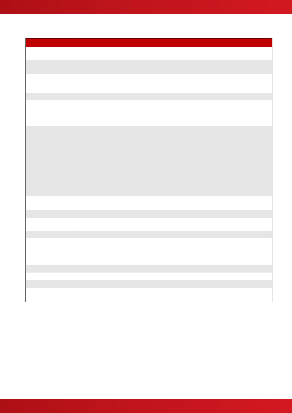
Specifications:
Item
Specification Details
Approvals
All Power Supply Units comply with the requirements of EN54-4:1997 +A1:2002 +A2:2006, EN55022
class B emissions limits & EN60950-1:2006 safety standards.
Input Supply
1.5A PSE : 220-240V AC, 50/60Hz, Fuse T3.15H250
3.0A/5.0A PSE : 200-240V AC, 50/60Hz, Fuse T3.15H250
Output Voltage
Max 28.5V DC, Min 19.7V DC at minimum battery voltage of 21V1with mains disconnected (Output
voltage is VBAT –1.3V max. at Imax.a)
Ripple 200mV max (Note: 1V p-p including switching frequency noise).
Charger Voltage
27.4V DC nominal at 20°C temperature compensated over the range -5°C to +40°C
Output Current
(Imax.a = Imax.b)
(Imin = 10mA)
1.5A PSE : 1.0A continuous load, 0.5A battery charge
3.0A PSE : 2.0A continuous load, 1.0A battery charge [3.0A to load if configured for PSE only2]
5.0A PSE : 3.0A continuous load, 2.0A battery charge [5.0A to load if configured for PSE only2]
Dimensions Enclosure
IP30 (H x W x D)
MXP-049 : 320 x 345 x 88mm 3Kg without batteries
MXP-050-001 : 320 x 345 x 88mm 3Kg without batteries
MXP-050-002 : 425 x 406 x 125mm 5Kg without batteries
MXP-051 : 425 x 406 x 125mm 5Kg without batteries
MXP-051/D : 425 x 406 x 190mm 7Kg without batteries
MXP-549 : 263 x 246 x 85mm 3Kg without batteries
MXP-550 : 378 x 338 x 110mm 5Kg without batteries
MXP-550D : 410 x 363 x 185mm 7Kg without batteries
MXP-551 : 378 x 338 x 110mm 5Kg without batteries
MXP-551D : 410 x 363 x 185mm 7Kg without batteries
Dimensions Cage
(H x W x D)
1.5A PSE : 105 x 94 x 38mm 250g
3.0/5.0A PSE : 184 x 94 x 58mm 690g
Environment
Indoor, Dry
Operating
Temperature
-5ºC to +40ºC @ full load output
Relative Humidity
95% non-condensing (maximum)
Standby Battery and
Internal Resistance
2 x 12V Sealed Lead-Acid Type (Yuasa or Powersonic recommended)
1.5A PSE : 3.3Ω 1.2Ah minimum to 7Ah maximum
3.0A PSE : 1.6Ω 1.2Ah minimum to 18/24Ah maximum
5.0A PSE : 0.8Ω 1.2Ah minimum to 38Ah maximum
Fault Output
Volt free change-over contacts rated 1A @ 30V dc (all models)
External Indication
Green: Power indicator, Amber: Fault indicator
On board indication
Mains Fail, Charger Fail, Battery open circuit, Battery Low & Heartbeat
Deep Discharge
All models incorporate battery deep discharge protection (19V)
As our policy is one of constant product improvement the right is therefore reserved to modify product specifications without prior notice. E&OE
1
The battery final discharge voltage recommended by battery manufacturer.
2
NOT EN54-4 Compliant. EN54-4 specifies the provision of two power sources. These should comprise a main supply (AC mains) and a
stand-by supply (battery).

www.advancedco.com
4
Table of Contents Page
1INTRODUCTION.............................................................................................................................................4
2EN54 FUNCTIONS .........................................................................................................................................5
3INSTALLATION:.............................................................................................................................................5
3.1 MOUNTING INSTRUCTIONS: .......................................................................................................................6
3.1.1 Mxp-049, Mxp-050, Mxp-051.............................................................................................................6
3.1.1.1 Mounting Peripheral Cards or OEM equipment.......................................................................................6
3.1.1.2 Fixing Points and Dimensions.................................................................................................................6
3.1.2 Mxp-549, Mxp-550, Mxp-551.............................................................................................................7
3.1.2.1 Fixing Points and Dimensions.................................................................................................................7
3.1.2.2 Mounting batteries...................................................................................................................................8
3.1.3 Mxs-049, Mxs-050, Mxs-051 PSE Modules.......................................................................................8
3.2 WIRING INSTALLATION..............................................................................................................................9
3.2.1 AC Mains Wiring ................................................................................................................................9
3.2.1.1 Cable Gland ............................................................................................................................................9
3.2.2 Output Connections: ....................................................................................................................... 10
3.2.2.1 To Load:................................................................................................................................................10
3.2.2.2 To Battery:.............................................................................................................................................10
3.2.2.3 Fault Output Connections:.....................................................................................................................10
3.2.2.4 Remote LED indication:.........................................................................................................................11
3.2.2.5 Charger / PSE Only Configuration:........................................................................................................11
3.2.2.6 Serial Communications:.........................................................................................................................11
3.2.2.7 Remote Temperature Sensor................................................................................................................12
4COMMISSIONING:...................................................................................................................................... 13
5MAINTENANCE: ......................................................................................................................................... 14
5.1 STANDBY BATTERIES ............................................................................................................................ 14
1 Introduction
The Advanced 1.5A, 3.0A and 5.0A Power Supply Units can be used for any fire alarm system installation that
specifies EN54-4 Power Supply Equipment.
Suited for almost any application (except for CIE in separate cabinet), the power supply unit/battery charger has
been developed using the latest surface mount technology to provide a high efficiency switch mode power
supply.
The power supply units are available in fully enclosed construction providing power and fault indication or
alternatively in caged versions for mounting into existing enclosures of various sizes to suit different battery
capacities.
Features
A range of power supply equipment with power output options to suit most applications.
Wide AC Input range on the 3.0A and 5.0A versions
PSE and Charger or PSE only options on the 3.0A and 5.0A versions.
A Serial Link option is provided on the 3.0A and 5.0A versions. Allows reporting of PSE status and
voltages to compatible control panel / modules.
All models monitor the battery internal series resistance.
A Remote battery sensing option is provided on the 3.0A and 5.0A versions.
www.advancedco.com
5
2 EN54 Functions
This Fire Alarm Power Supply complies with the requirements of EN54-4.
P.S.E Functions
EN54-4 Clause
Operation from a main power supply
Operation from a standby battery
Monitor and Charge the Standby Battery
Recognise and Notify Supply Faults
5.1
5.2
5.3
5.4
The power supplies comprise an AC Mains input circuit (refer to specifications), a single output DC voltage
supply circuit
3
and a battery circuit.
3 Installation:
These instructions cover the installation, commissioning and maintenance of the Mxp-049, Mxp-050, Mxp-051
and Mxp-549, Mxp-550, Mxp-551 models.
For use of the Mxs-049, Mxs-050 & Mxs-051 in an OEM / customer supplied enclosure, these power supplies
should be mounted in an appropriate sized enclosure suitable for the intended batteries to be used. The
minimum protection rating of the enclosure must be to IP30 and the power supply must be earthed. Take note of
the important safety information in the remainder of this document. An input supply lead with AC Mains Terminal
Block is supplied in the kit.
4
NB: The batteries must not be mounted in an enclosure separate from the power supply since this could affect
the temperature compensating charging characteristics, resulting in incorrectly charged batteries.
The power supply modules are also incorporated into other boxed peripheral units. The information in this
document is applicable to these power supplies. Refer to the additional data sheet supplied with each boxed
unit for details on the installation, configuration and use of the peripheral function.
3
EN54-4 requires that when an EN54-2 CIE is housed in a separate cabinet to the EN54-4 PSE, the CIE shall be supplied via at least two
monitored supply (transmission path) circuits such that a short or open circuit in one circuit does not prevent supply of power to the CIE.
4
Advanced Electronics Ltd does not warrant that the equipment continues to satisfy the requirements for compliance with the EMC
Emissions Directive, Low Voltage Directive or EN54-4 when caged units are mounted in a customer’s own enclosure. Ensure continued
compliance through appropriate testing and/or notified body certification.
www.advancedco.com
6
3.1 Mounting Instructions:
3.1.1 Mxp-049, Mxp-050, Mxp-051
The Mxp-049, Mxp-050 and Mxp-051 are power
supplies mounted within an IP30 steel enclosure. These
can accommodate 7Ah, 18Ah up to 38Ah capacity
batteries depending on enclosure size (refer to
specifications page).
When batteries are installed, the Mxp-051 can weigh in
excess of 16Kg. Use appropriate fixing hardware to
secure the panel to the wall.
For example, drill the required holes in the supporting
wall using a drill bit diameter 7.0 mm and plug with a
suitable 40mm long expansion plug. Affix the panel to
the wall with M5 screws (length 40mm) or No.10 screws
(length 1½”).
Ensure that there is sufficient space to allow the cover
to be removed / opened when the panel is finally
mounted.
An example of the Mxp-051 is shown opposite.
3.1.1.1 Mounting Peripheral Cards or OEM equipment.
Space is provided in which to mount ancillary equipment or printed circuit cards
5
.
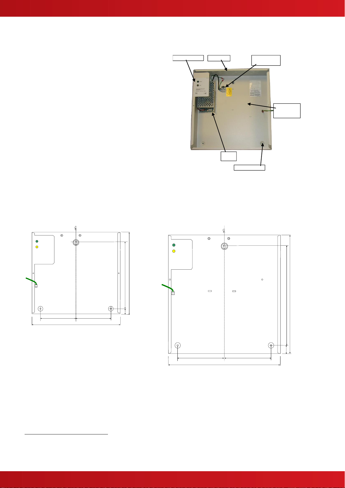
3.1.1.2 Fixing Points and Dimensions
135
135
340
24
315
255
Power
Fault
Earth
Lead to
Cover
7Ah Enclosure
135
135
340
30
420
255
Power
Fault
Earth
Lead to
Cover
17Ah / 38Ah Enclosure
5
Advanced Electronics Ltd does not warrant that the equipment continues to satisfy the requirements for compliance with the EMC
Emissions Directive and Low Voltage Directive when equipment, other than that manufactured by Advanced Electronics Ltd and installed
in accordance with the supplied documentation, is mounted in the enclosure. Ensure continued compliance through appropriate testing
and/or notified body certification.
Knockouts
Space for
Peripheral
Cards
Mains Terminal
Block
Fixing Points x3
PSE
Status Indicators
www.advancedco.com
7
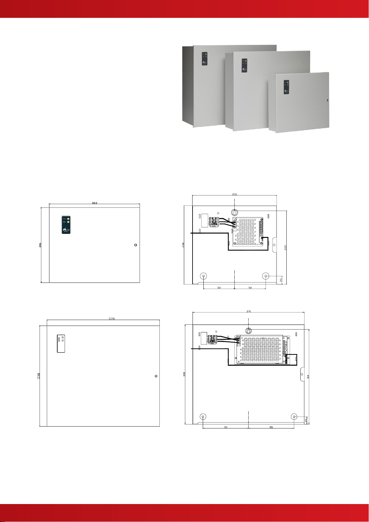
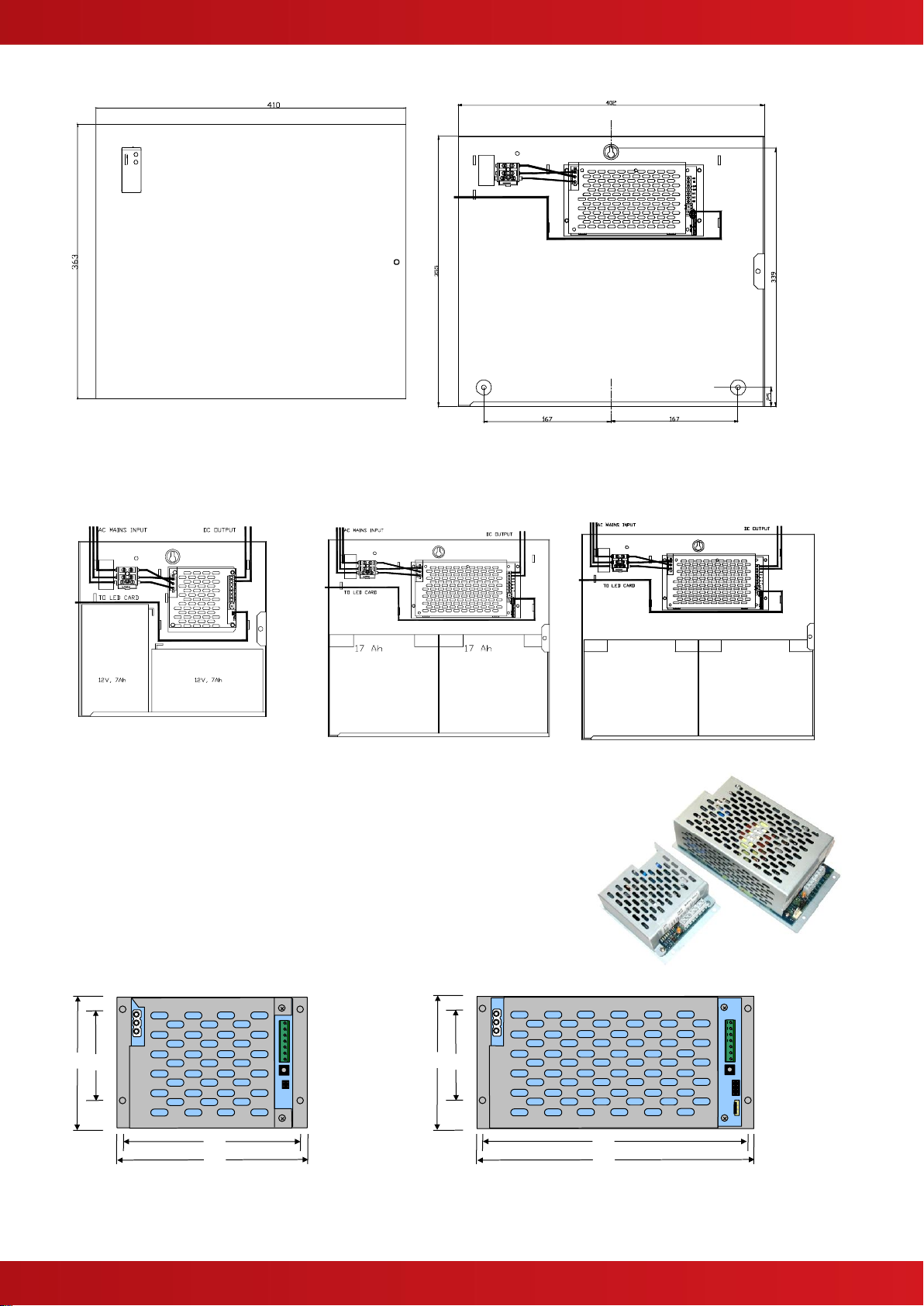
3.1.2 Mxp-549, Mxp-550, Mxp-551
The Mxp-549, Mxp-550 and Mxp-551 are power
supplies mounted within an IP30 steel enclosure.
These can accommodate 7Ah, 18Ah up to 38Ah
capacity batteries depending on enclosure size
(refer to specifications page).
When batteries are installed, the Mxp-551 can
weigh in excess of 16Kg. Use appropriate fixing
hardware to secure the panel to the wall.
For example, drill the required holes in the
supporting wall using a drill bit diameter 7.0 mm
and plug with a suitable 40mm long expansion
plug. Affix the panel to the wall with M5 screws
(length 40mm) or No.10 screws (length 1½”).
The cover is hinged on the left hand side. Ensure
that there is sufficient space to allow the cover to
be opened when the panel is finally mounted.
3.1.2.1 Fixing Points and Dimensions
MXP-549
Note: This unit does not accept the Mxs-049 module. The PSE
PCB and cage are mounted directly to the back box.
MXP-550 & MXP-551
www.advancedco.com
8
MXP-550/D & MXP-551/D
3.1.2.2 Mounting batteries
MXP-549
MXP-550 & MXP-551
MXP-550/D & MXP-551/D
3.1.3 Mxs-049, Mxs-050, Mxs-051 PSE Modules
The PSE modules can be installed in Mx-5000 Rack and other Utility
enclosures.
Refer to the relevant product manuals for further information.
The dimensions and fixing points are shown below.
105
98
66
94
1.5A PSE
184
174
66
94
3.0A / 5.0A PSE
24Ah / 38Ah
24Ah / 38Ah
www.advancedco.com
9
3.2 Wiring Installation
3.2.1 AC Mains Wiring
The power supply is classified as Class1 equipment
construction and must be earthed in accordance to
EN60950 recommendations.
Route the high voltage mains AC wiring into the
enclosure using a suitable knockout and keeping the AC
wiring away from any circuit boards and all other wiring.
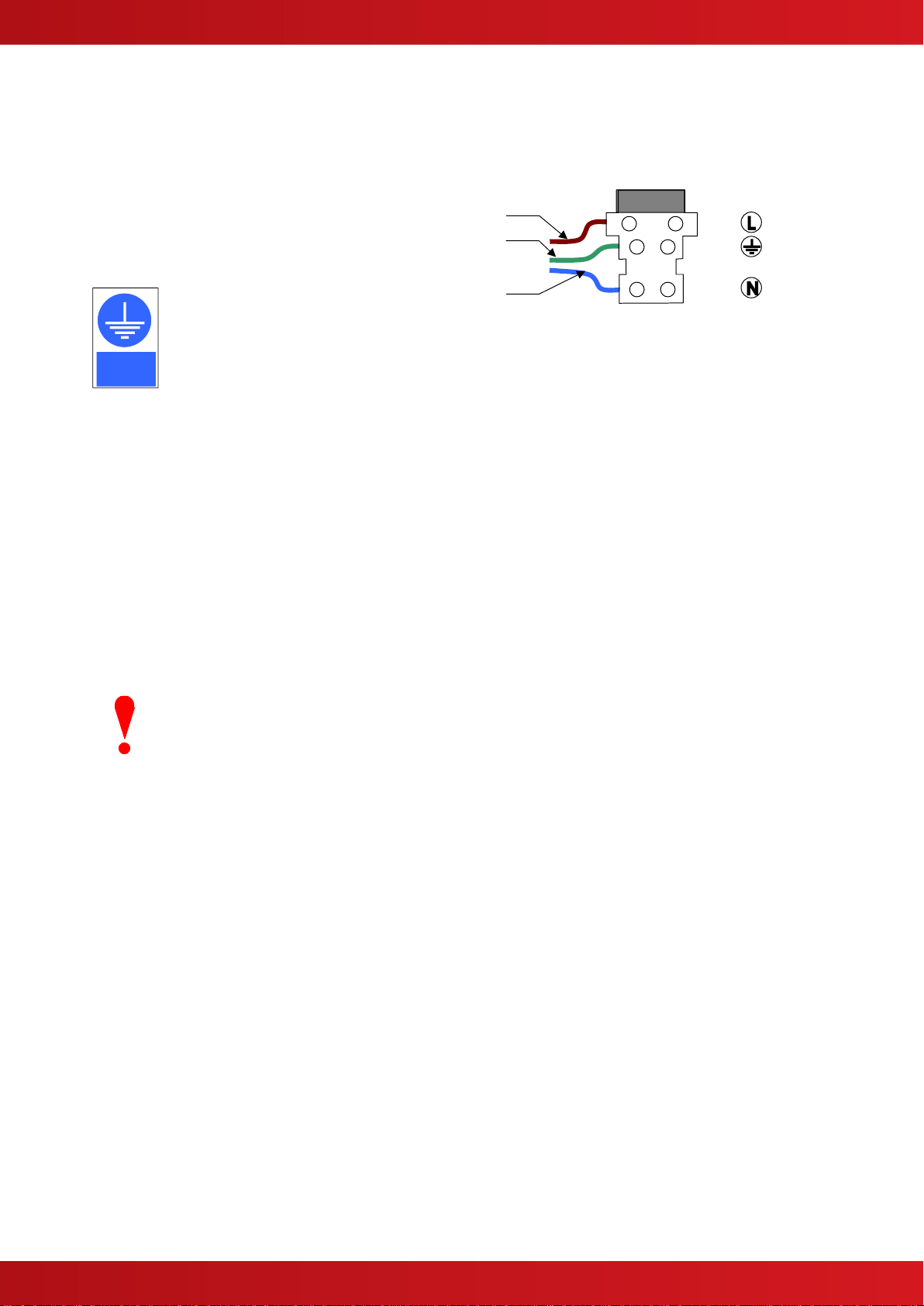
The panel must be connected to the supply
earth through the power cable.
The mains input connector is shown in the
diagram opposite. Note the positions of the
earth, neutral and live terminal connections.
These are clearly marked on the label next
to the connector. The connector block
contains an integral fuse holder for a 20mm fuse.
Secure the mains input wiring using a tie wrap as close
to the terminal block as possible.
The fuses are rated as follows:
T 3.15A H 250V (for all models)
Replace with correct rating and specification only.
Connect the PSE to the mains supply via a readily
accessible, disconnect device (Isolation Switch) and
suitable earth fault protection incorporated in the building
installation wiring.
FUSE
Brown
Grn/Yel
LIVE
EARTH
NEUTRAL
PSU Internal Mains
Wiring
Blue
Field Connections
AC Mains terminations –Mxp-049
The Mains cable should be a minimum cable size
of 0.5mm² for the 1.5A PSE & 0.75mm² for the
3.0A/5.0A PSE rated at 250V and fused via a 5A
anti-surge fuse. Maximum cable size is limited to
4mm².
Keep all mains wiring separate from the Extra Low
Voltage (ELV) battery cables and power supply
output cables.
3.2.1.1 Cable Gland
The cable gland and any cord clamp bushings used in routing the Mains cable
through the 20mm knockout must have a minimum flame-retardant rating of 94HB.
Suggested glands and bushings are: -
Type
Gland IP65 –Brass M20, EExd / Eexe
Gland IP68 –Nylon 66 M20 Black, UL94V2
Bushing –Nylon 66 M20 Black, UL94V2
Manufacturer
Lappcable
Multicomp
Multipcomp
Must be
earthed
www.advancedco.com
10
3.2.2 Output Connections:
3.2.2.1 To Load:
Connect the 28V output connections to the load via terminals
VO+ & VO–respectively via appropriately rated cable for the
output rating:
For 3.0A/5.0A PSE a minimum 0.75 mm²
For 1.5A PSE a minimum of 0.22mm²
NB Maximum cable size is limited to 2.5mm²
Refer to diagrams opposite for the positions of all output
connections.
Maximum Cable Resistance:
The voltage drop on the output circuit should be calculated to
ensure that the minimum voltage at the end of the circuit
exceeds the minimum required by the device at the minimum
PSE output voltage.
The voltage at the end of the circuit is given by:
Minimum Load Voltage = VOUT(MIN) –(ILOAD x RCABLE)
Minimum Output Voltage (VOUT(MIN)) is VBAT(MIN) –0.5V =
20.5V
Load Current (ILOAD) is the sum of the loads presented by the
devices.
Cable Resistance (RCABLE) is the sum of the cable resistance
in both cores x cable length.
Cable Resistance (RCABLE) for 1.0mm2is 0.036Ω / m
Cable Resistance (RCABLE) for 1.5mm2is 0.024Ω / m
Cable Resistance (RCABLE) for 2.5mm2is 0.015Ω / m
BAT –
BAT +
VO –
VO +
COM
N/O
N/C
Remote LED
Start from
battery Switch
Fault
Output
Configuration
Serial Link
Common Arrangement
Not on 1.5A SE
Remote Temp
Sensor
Jumper Link for local
temperature sensor
Observe that the load is connected
with the correct polarity!
Route the wiring away from any
mains connections.
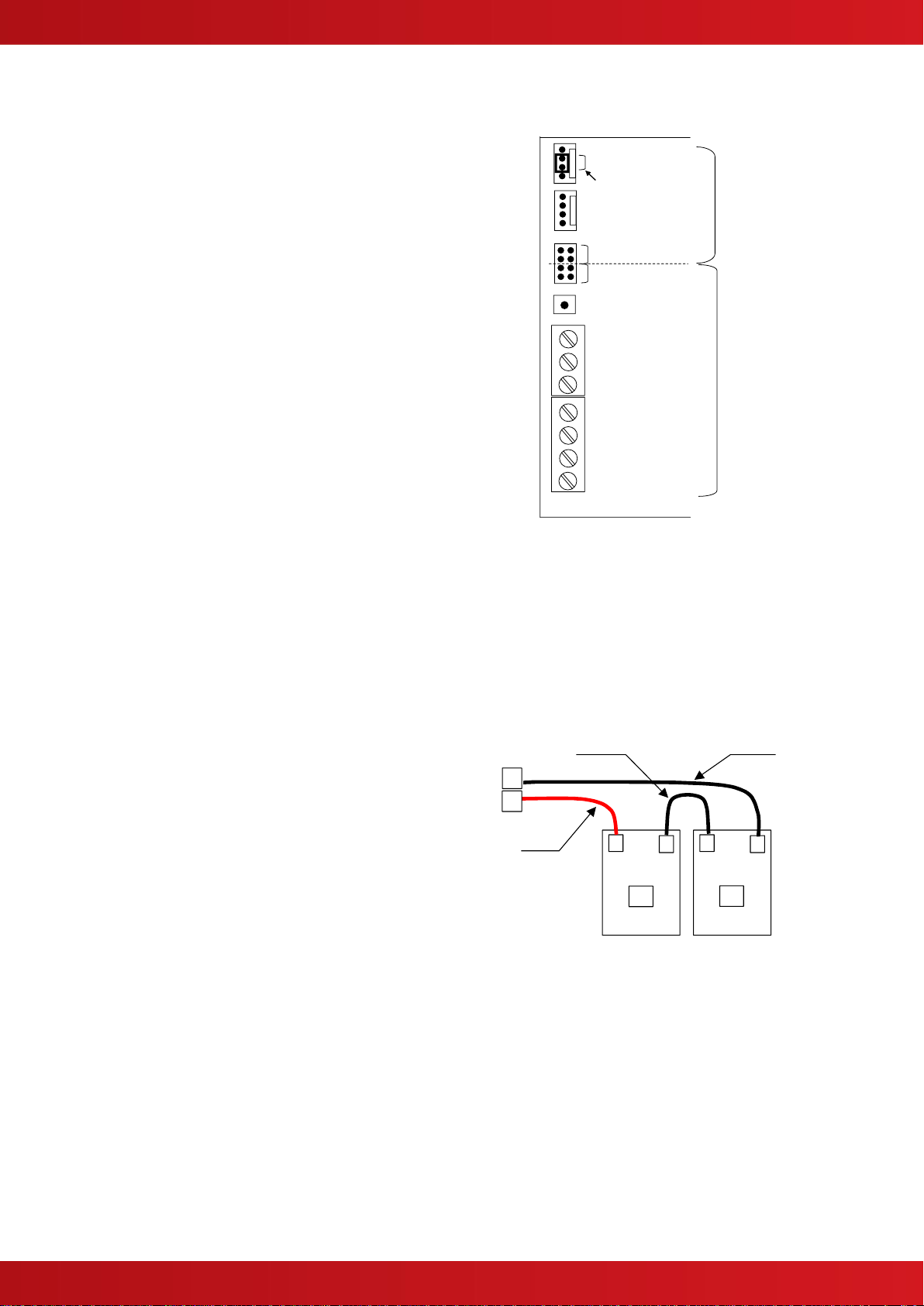
3.2.2.2 To Battery:
The system is designed to charge 24V batteries or
two 12V batteries connected in series. Refer to
diagram opposite.
Use the short black connection link to connect the
batteries.
Use the Red & Black leads provided to connect the
batteries to the BAT+ & BAT–terminals on the PSU.
Take care to observe the correct polarity and
ensure the battery leads do not become shorted
together!
Mount the batteries on the bottom of the enclosure.
+
-
+
-
+
-
#1
#2
RED
BLACK
Link Cable
3.2.2.3 Fault Output Connections:
Power supply/charger fault outputs are provided for in the form of volt free changeover contacts designated
COM, N/O & N/C. These are available via three terminal blocks screws –refer to diagram above.
The “Fault” relay is held in a normally energised state. It will fail to safety (de-energise) under any power
supply/charger “Fault” conditions.
www.advancedco.com
11
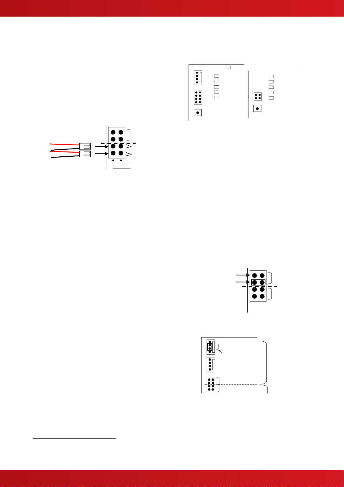
3.2.2.4 Remote LED indication:
A pin header, J1, provides a means for remote/ external
indication of “Power” and “Fault” indications.
The Mxp-049, Mxp-050 & Mxp-051 models are supplied
fitted with separate Green and Amber LED Indicators.
Refer to diagram below for how to connect these
assemblies to the PSU.
Replacement parts are available. Green = Mxs-026-GRN
and Amber = Mxs-026-YEL
The Mxp-549, Mxp-550 & Mxp-551 are supplied with an
LED PCB mounted on the cover. This is connected to the
PSE module using a 4-Way cable.
Remote LED Connector
FAULT
POWER
RED
BLACK
RED
BLACK
RED
BLACK
NOT FITTED ON
1.5A PSE
GREEN
AMBER
The Green “Power” indicator will be ON continuously
when the power supply is being supplied with mains
power. This indicator will flash when the mains supply is
off and the power supply is being powered from its
battery source.
The Amber “Fault” indicator will be ON continuously if
any of the Fault conditions listed opposite are present:
Note: Faults may not be indicated immediately. They will
be indicated within the times permitted in EN54-4 (see
opposite for nominal times).
On-board Indicators
The following indicators on the printed circuit card
give further diagnostic information.
1.5A
3.0A/5.0A
1
3
4
5
6
2
1
3
4
6
2
[1] MAINS FAILURE : AC Mains Supply
failure (30 seconds)
[2] CHARGER FAULT : Battery charger output
failure (2 minutes)
[3] BATTERY OC : Battery disconnected
(2 minutes)
[4] BATTERY LOW : Battery High Cell
Resistance (3 minutes)
[5] BATTERY ON : Output Voltage is
supplied from the
battery
[6] HEARTBEAT : Microprocessor is
running (flashes)
3.2.2.5 Charger / PSE Only
6
Configuration:
The 3.0A and 5.0A PSE models can be configured
for operation as a PSE + CHARGER or PSE ONLY
(if battery standby is not required).
A pin header, J1, provides a means for selecting this
operation.
Remote LED
Connections
NOT FITTED ON
1.5A PSE
PSE ONLY
PSE + CHARGER
Fit Jumper in required
location. The unit is
supplied as default set for
PSE + Charger Mode of
operation as shown.
3.2.2.6 Serial Communications:
The 3.0A and 5.0A PSE models can be
connected to a compatible control panel or other
peripheral module for communication of the PSE
status and voltage / current measurements.
A latching pin header, PL2, is provided –see
opposite.
Information is provided with the unit / module
where this compatible feature is provided.
BAT –
BAT +
VO –
VO +
COM
N/O
N/C
Remote LED
Start from
battery Switch
Fault
Output
Configuration
Serial Link
Common Arrangement
Not on 1.5A PSE
Remote Temp
Sensor
Jumper Link for local
temperature sensor
6
NOT EN54-4 Compliant. EN54-4 specifies the provision of two power sources. These should comprise a main supply (AC mains) and a
stand-by supply (battery).
www.advancedco.com
12
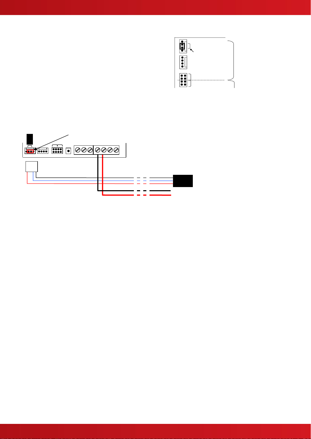
3.2.2.7 Remote Temperature Sensor
Provision is made on the 3.0A and 5.0A PSE
models for the connection of a remote battery
temperature sensor (Mxp-501). This is for
applications where the modules are installed in
rack mount enclosures or in large enclosures and
where the batteries are not located immediately
next to the module.
A latching pin header, PL3, is provided for
connection of the temperature sensor –see
opposite and below.
If a remote temperature sensor is not used,
ensure the jumper is fitted to the centre two pins.
BAT –
BAT +
VO –
VO +
COM
N/O
N/C
Remote LED
Start from
battery Switch
Fault
Output
Configuration
Serial Link
Common Arrangement
Not on 1.5A PSE
Remote Temp
Sensor
Jumper Link for local
temperature sensor
If neither a jumper nor a remote sensor is fitted, the PSE
module will indicate a charger fault condition.
Remove the jumper and plug the Mxp-501 into the connector. Route the sensor cable along with the battery
leads. Use the supplied tie-wraps to tie the sensor cable to the battery leads so that the encapsulated sensor is
located close to the batteries. The sensor cable is 500mm in length.
Jumper –centre two pins
Battery Leads
Sensor
www.advancedco.com
13
4 Commissioning:
When all connections in the Installation section have been made and checked for correct wiring, switch on the
mains power supply; the following conditions should occur:
1 The green “Power” LED should be ON, the “Fault” LED should be OFF.
2 The load should be supplied with power, check this with a voltmeter at the –VO & +VO terminals, the
reading should be between 25 & 28.5 volts
7
.
3 The batteries should be charging, check this by connecting a voltmeter across the –BAT & +BAT
connections, depending on the state of discharge of the batteries, the voltage should be greater than 24
volts and for batteries approaching their full charge, the output voltage should be approximately 27.4 volts
at an ambient temperature of 20°C
4 All on-board diagnostic LED indicators should be OFF, the “Heartbeat” indicator should be FLASHING.
5 The “Fault” relay should be energised. Check that there is a connection between common and normally
open (N/O). This connection should indicate a short circuit when checked with a test meter on the
continuity setting.
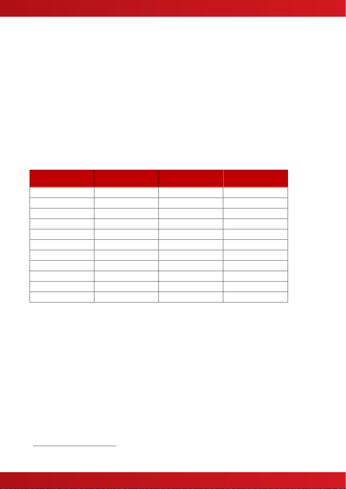
The following table indicates the charger voltage against temperature when the batteries are fully charged.
Ambient
Temperature ° C
Charger output
voltage (minimum)
Charger output
voltage (Nominal)
Charger output
voltage (Maximum)
-5
27.90
28.10
28.32
0
27.72
27.96
28.20
5
27.54
27.80
28.08
10
27.36
27.66
27.96
15
27.24
27.50
27.78
20
27.12
27.36
27.60
25
27.00
27.20
27.42
30
26.88
27.06
27.24
35
26.76
26.90
27.06
40
26.64
26.76
26.88
TABLE 1
NB: The charger is designed to charge Yuasa & Powersonic sealed lead acid batteries only. Other
manufacturers’ batteries may have different temperature / charge characteristics.
7
The Output will gradually increase until its optimum level (dependent on temperature) is reached.

www.advancedco.com
14
5 Maintenance:
Maintenance of the power supply and charger should be minimal. The batteries, however, do have a limited life
span and a maintenance program should be in place to determine battery replacement schedules.
It is recommended that the charger output should be checked on a yearly basis to ensure the charging
characteristics have not drifted. Refer to Table 1 above for checking this parameter.
5.1 Standby Batteries
Expected Life - 3-5 years at an ambient temperature of 20°C
Replacement Schedule - As above. However, note that the expected battery life is shortened by an
increase in ambient temperature. The life reduces by 50% for every 10°C rise above ambient. This
should be taken into account when assessing battery replacement schedules. Refer to battery
manufacturer manuals for further information.
Manufacturer / Part Numbers - YUASA POWERSONIC
4AH NP4-12 5AH PS-1250-F1
7AH NP7-12 7AH PS-1270
12AH NP12-12 12AH PS-12100-F1
18AH NP18-12 18AH PS-12180-NB
24AH NP24-12B 26AH PS-12260-NB
38AH NP38-12 40AH PS-12400
STOP
For optimum performance and charge retention, Yuasa recommend that batteries, up to
6 months old from date of manufacture, are ‘top-charged’ prior to installation.
To perform the top-charging, use a separate supply and charge at 2.4V per cell (i.e.
14.4V per battery) for 20 hours prior to installing the batteries.
STOP
It is not recommended to use batteries that are older than 6 months from the date of
manufacture on a new installation.
It is quite normal for lead-acid batteries to vent hydrogen when being
charged.
The panel is adequately ventilated to dissipate this hydrogen. DO NOT
seal the enclosure or install in a sealed enclosure or cavity.
STOP
It is not recommended to use batteries that are older than 6 months from the date of
manufacture on a new installation.
BATTERY DISPOSAL
Re-cycle all exhausted batteries.
Return to the battery manufacturer or dispose of batteries in accordance
with the applicable local legislation.

www.advancedco.com
15
USER NOTES

www.advancedco.com
Advanced Electronics Ltd
Moorland Way, Cramlington, Northumberland, NE23 1WE UK
Tel: +44 (0)1670 707 111 Fax: +44 (0)1670 707 222
Email: sales@advancedco.com Web: www.advancedco.com
Doc Number: 680-132
Revision: 07
Table of contents


