Il modulo alimentatore caricabatteria
IPS12100 è stato sviluppato secondo i
criteri di qualità, affidabilità e prestazioni
adottati dalla INIM Electronics. I compo-
nenti utilizzati garantiscono idonei requisiti
di funzionamento quando le condizioni am-
bientali esterne al modulo sono in accordo
con la categoria 3k5 della IEC 721-3-3.
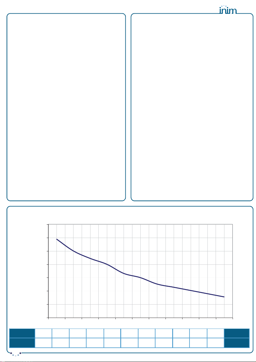
Il modulo di alimentazione IPS12100
fornisce una tensione stabilizzata a 13,8V
ed una corrente massima di 5A. Le uscite
sono protette da sovraccarichi, corto circuiti
ed inversione accidentale delle polarità
dell’eventuale batteria ad esse collegata.
Installazione
Collegare i conduttori provenienti dalla rete
elettrica alla morsettiera
1
(vedi
Fig. 1
).
ATTENZIONE!
• E’ necessario collegare il conduttore
di terra.
• I conduttori provenienti dalla rete
elettrica devono essere fascettati e
fissati in prossimità del loro ingresso
al modulo alimentatore.
Per il fissaggio del IPS12100 all’interno di
contenitori od apparecchiature utilizzare i
due semifori di fissaggio 2.
Ruotando il trimmer
3
è possibile eseguire
dei piccoli aggiustamenti della tensione di
uscita; il modulo viene fornito già tarato.
The IPS12100 Switching power supply/
Battery charger has been designed and
made to the highest standards of quality
and performance. INIM Electronics guar-
antees proper functioning of the compo-
nents utilized in this product when the
environment external to the module com-
plies with Class 3k5, IEC 721-3-3.
The IPS12100 unit supplies a regulated
voltage of 13.8V and a maximum current
of 5A. Its power output is protected
against overload, short-circuit and acci-
dental inversion of the polarity of the con-
nected batteries.
Installation
Connect the mains wiring to the input ter-
minals 1(see Fig. 1).
ATTENTION!
• This device must be earthed.
• Using a plastic cable band, bunch the
mains wires and fasten them near to
the mains wire entry.
Using the mounting holes 2, secure the
IPS12100 inside its housing.
The power supply is calibrated at the fac-
tory, however, minor adjustments of the
output voltage can be made using the
trimmer 3.
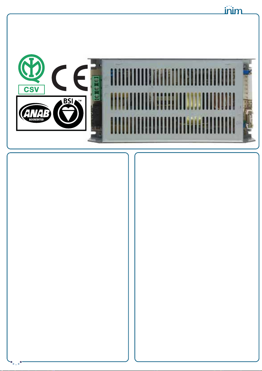
IPS12100
Alimentatore/Caricabatteria switching da 13,8V dc 5A
13.8V dc 5A switching Power Supply/Battery Charger
Certificato EN60950-1
EN60950-1 certified
DCMIINIEIPS12100-R121-20101203