It is recommended that, in all areas where there are unsupervised children, that a suitably
rated current limiting device having a resistance of not less than 500 ohms be connected
between the energiser and the electric fence.
The appliance is not intended for use by young children or the disabled.
Do not place combustible materials near the fence or energiser connections. In the event of a
fire, the energiser must be disconnected.
Do not dismantle and assemble the main part ad arbitrium. Do not attempt to make any
changes to the energiser yourself.
Young children must be supervised to ensure that they do not play with the appliance.
An electric animal fence shall not be supplied from two separate energisers or from
independent fence circuits of the same energiser.
For any two separate electric animal fences, each supplied from a separate energiser
independently timed, the distance between the wires of the two electric animal fences must
be at least 2.5m.
Barbed wire or razor wire will not be electrified by an energiser.
A non-electrified fence incorporating barbed wire or razor wire may be used to support one
or more off-set electrified wires of an electric animal fence. The supporting devices for the
electrified wires shall be constructed so as to ensure that these wires are positioned at a
minimum distance of 150 mm from the vertical plane of the non-electrified wires. The barbed
wire and razor wire shall be earthed at regular intervals.
Where an electric animal fence crosses a public pathway, a non-electrified gate should be
incorporated in the electric fence at that point or a crossing by means of stiles should be
provided.At any such crossing, the adjacent electrified wires should carry warning signs.
In areas of public access, use an electric fence warning sign every 10m (33ft) to identify the
electrified wire(s).
Crossing with overhead power lines should be avoided wherever possible. If such a crossing
cannot be avoided, it should be made underneath the power line and at right angles.
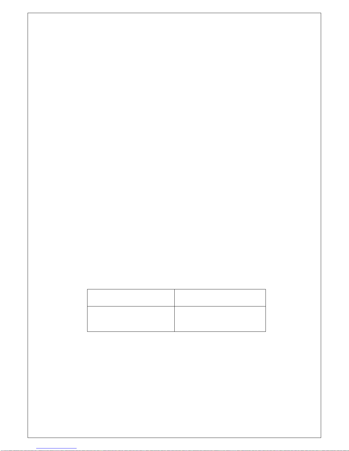
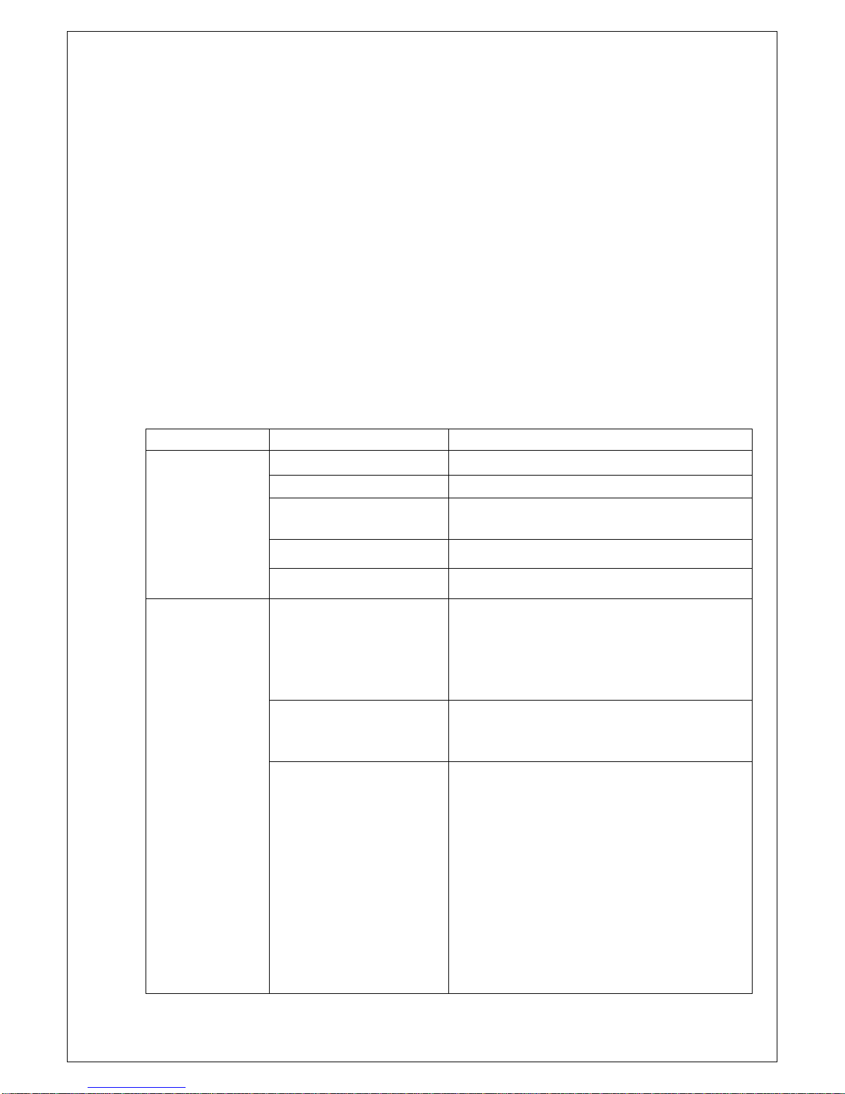
If connecting leads and electric fence wires are installed near an overhead power line, the
clearances should be not less than those shown below:
If connecting leads and electric fence wires are installed near an overhead power line, their
height above the ground should not exceed 3m.
This height applies either side of the orthogonal projection of the outermost conductors of the
power line on the ground surface, for a distance of:
•2 metres for power lines operating at a nominal voltage not exceeding 1000 volts;
•15 metres for power lines operating at a nominal voltage exceeding 1000 volts.