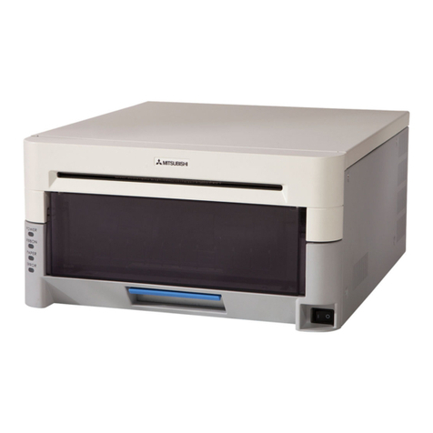
Advanced MxPro 5 User manual

www.advancedco.com
Printer
The operation and functions described in this manual are available from Software Version Mx5000-050-02 onwards.

www.advancedco.com
Specifications:
Models, Sales Order Parts:
Mxp-512 Mx-5000 Internal Printer
Applications / Limitations:
When the printer is fitted, only four of the eight key-switch positions can be used.
Compatibility:
All Mx-5000 Series Panels except Mx-5101S.
The printer fully supports the complete Western European character set –Code Page 1252. It is
possible to support other code pages.
Item
Specification Details
Temperature
-5C to +40C
Relative Humidity
93%
DC Power Supply
24V
Current (Quiescent)
18mA (max)
Current (Printing)
Typical 30% duty cycle
538mA (average) / 1.0A (peak) @ 24V
Printer Type
Thermal dot matrix
Printer Resolution
384 dots per line
Paper
Thermal, 58mm wide x 32mm diameter roll (10m Long)
Sensor
Paper Out / Door Open
Approvals
G210022
As our policy is one of constant product improvement the right is therefore reserved to modify product specifications without prior notice

www.advancedco.com
3
Table of Contents Page
1INTRODUCTION.............................................................................................................................................3
2INSTALLATION..............................................................................................................................................4
2.1 MOUNTING THE PRINTER ASSEMBLY ..........................................................................................................4
2.2 CABLE INSTALLATION...............................................................................................................................5
2.3 INSTALLING THE PAPER ROLL....................................................................................................................6
2.4 LOGO PROGRAMMING...............................................................................................................................6
2.5 FAULT LED..............................................................................................................................................6
3CONFIGURATION..........................................................................................................................................7
4OPERATION...................................................................................................................................................8
4.1PRINT MENU ............................................................................................................................................8
4.2 TEST MENU..............................................................................................................................................8
1 Introduction
Fast and quiet printing
Automatic printing of fire alarms, faults, alarms and test are configurable
On-demand printing of status for inputs, outputs, disablements, event log and network faults
In-built self-diagnostics
Bi-directional communications with the panel electronics
Front panel paper feed button
User / installer logo option
Compact design with simple paper loading
Printing is fully supported during AC Power failures

www.advancedco.com
4
2 Installation
Isolate ALL sources of power before installing or removing printed circuit boards.
Observe anti-static precautions at all times when handling printed circuit boards.
2.1 Mounting the printer assembly
The printer is mounted onto the display plate in a pre-defined aperture.
Using a pair of strong side cutters, cut through the
1mm pips of the metal plate as shown below:
Using a sharp knife and working from the front
face, cut through the membrane label using the
outer edge of the aperture as a guide.
When the aperture plate is free, trim off and tidy
the edge of the label to the edge of the aperture.
Take care not to damage the fascia label.
Offer up the printer to the aperture and
guide the printer into position (at an angle)
ensuring that the connector on the PCB does not collide with the metalwork.
Push into position. Open up the paper roll aperture and then secure the printer mechanism using the two self-
tapping screws in the two holes either side of the printer paper roll recess.
To Base
Card
Printer
aperture
Pips

www.advancedco.com
5
2.2 Cable Installation
Remove the existing ribbon cable between the display and the base card.
The supplied cable is provided with three connectors. Plug one connector into the display card and then plug
the second connector into the printer.
Route the cable through the clamp and plug into the connector on the base card (ensure that the heat shrink
protection is in place under the tabs on the base card chassis plate.
The cable is common to all panels. Route the cable up the side of the back box and fold up any excess and use
the clamp to hold in place.
CAUTION: Observe orientation (bumps) on the connectors when mating with the headers.
Fixing
holes
Door release flap
To Base
Card
Cable
clamp

www.advancedco.com
6
2.3 Installing the paper roll
Using the door release flap, open the paper roll aperture door.
Insert the roll so that the paper exits from the top as shown over the top of the roller.
Close and snap shut the door.
Tear off any excess paper using the tear-off strip.
After power is applied, ensure that the fault LED is not illuminated.
Feed the paper, if required, using the paper feed button.
Refer to operation section for details of how to configure and operate and how to perform a test print.
2.4 Logo Programming
The printer can be configured to print the logo used on the panel display.
This logo will be printed on a power up test print.
The logo is automatically updated, along with the display, when using the PC Logo Tool.
2.5 Fault LED
The fault LED on the front face will illuminate if the printer detects an internal problem such as paper out / door
open.
The panel will also indicate a fault condition and give further details on the nature of the problem.

www.advancedco.com
7
3 Configuration
To configure and test the printer, select the printer options from the main level 2 menu.
[Print Menu]
INPUTS OUTPUTS FAULTS DISABLED
LOG FEED PAPER SETUP-PRINTER
Use the buttons to highlight and select the “SETUP-PRINTER” option
Use the buttons to highlight and press ✔to select the “Internal” option.
(Note: If required the panel will support simultaneous printing to an external printer too, but the “wide” option
should not be ticked when an internal printer is in use).
[FIRES] [ALARMS] [FAULTS] [TESTS]
-----
(Printer: Internal External/Wide)
✔--
On the top line tick any events that should be automatically printed as soon as they occur.
FIRES any device entering a fire condition
ALARMS any device entering a pre-alarm or plant alarm condition
FAULTS any fault detected by this panel
TESTS any device that is activated during a fire-test
On networked systems the fires, alarms and tests, if selected, print events occurring on other panels in the
network (The network configuration software will allow this to be restricted to just certain parts of the building if
required).
Escape from the printer set-up and move to the test menu. Perform a “Test – Print” and check that the printer is
functioning correctly.
For full information on the print displays and configuration options, please refer to the ‘User Manual’ (680-166).

www.advancedco.com
8
4 Operation
The printer will automatically print events as they occur depending on the settings defined in the configuration.
For full information on the print displays and options, please refer to the ‘User Manual’ (680-166).
4.1 Print Menu
The print menu also allows on-demand printing of a wide variety of items.
These options allow the present state of the system to be printed –not just from the panel to which the printer is
attached but also from anywhere on the network.
[Print Menu]
INPUTS OUTPUTS FAULTS DISABLED
LOG FEED PAPER SETUP-PRINTER
INPUTS - Prints device text, zone, device type, analogue value, device state
OUTPUTS - Prints device text, zone, device type, device state
FAULTS - Prints location and state of all devices in a fault condition
DISABLED –Prints location and state of all disabled devices
When any of these options are selected, the panel analyses the network and suggests default ranges for
printing (e.g. if DISABLED is selected, the display will suggest the first through to the last zone on the network
containing disabled devices). For example:
[ 2 Zone(s)with Inputs Disabled]
First Zone : 340
Last Zone : 373
(Press → to Start Print )
These defaults can be changed as required. Use the arrow and number keys to select and enter the required
zone numbers.
It is possible to feed the paper using the FEED PAPER menu option. The paper can also be advanced using the
button on the front of the printer.
4.2 Test Menu
To invoke the printing of a test print sequence, select the Test Menu:
[Test Menu] User 1 Node 1
ZONES DISPLAY BUZZER PRINTER
OUTPUTS
Use the buttons to highlight the Test Printer Option and press the ✔button to confirm. The panel
transmits 16 lines of test characters to the printer. The information sent is echoed on the display.
When the test print is completed, the display automatically reverts to the Test Options Menu.
Press the ‘Esc’ button at any time to cancel the test print.

www.advancedco.com
USER NOTES

www.advancedco.com
Advanced Electronics Ltd
Moorland Way, Cramlington, Northumberland, NE23 1WE UK
Tel: +44 (0)1670 707 111 Fax: +44 (0)1670 707 222
Email: sales@advancedco.com Web: www.advancedco.com
Doc Number: 680-193
Revision: 02
First Issued: 2013-mm-dd
Other manuals for MxPro 5
2
This manual suits for next models
2
Table of contents
