VEVOR VG-L5 User manual

1/2
VG-L5 (4050) User Guide
Welcome to use VG-L5 laser engraving machine. Please follow the
steps below to get started or scan the right QR code to watch videos and
browse related content to understand the installation and basic use of
the VG-L5 engraving machine.
Scan for videos and more guides
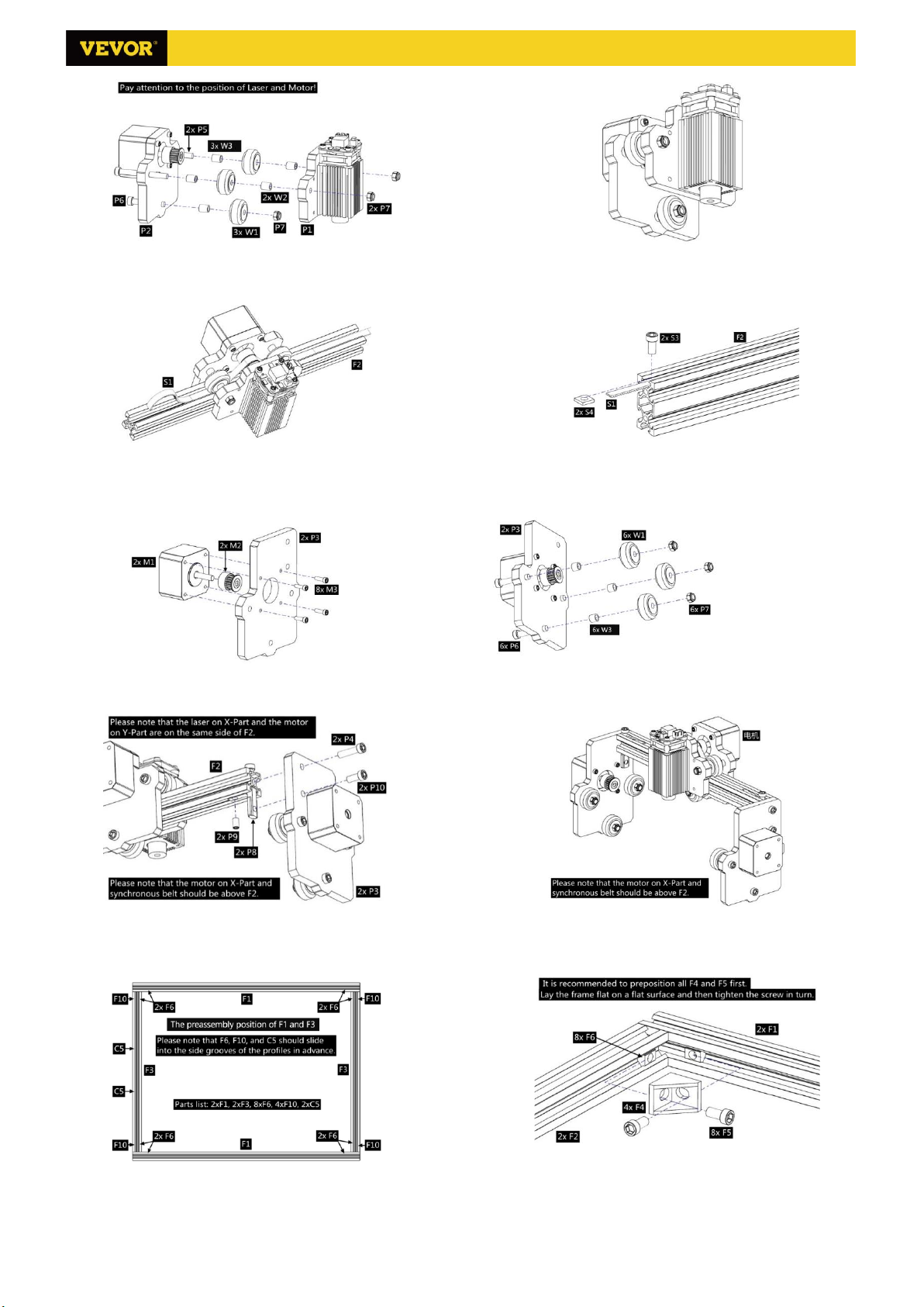
1. Assemble the machine
Please refer to the hardware manual for hardware assembly, which is ignored here.
Please go to the second step after the assembly is completed.
2. Download and run the software “VevorWorks”
Open our website www.VevorEngraver.com
Find the control software VevorWorks of VG-L5, then click to download to your computer.
Green software doesn't need to be installed. Decompress the file you downloaded just now. The software running
OS is Win7 Win8 and Win10.
Open the fold and double-click the VigoWorks.exe file to run the engraving software. The OS may prompt that the
software will use the network, please click OK (some computer systems do not prompt, if the software cannot use
the network, please allow it manually in the firewall).
This machine also supports other engraving software like Laser Grbl, Light Burn and so on.
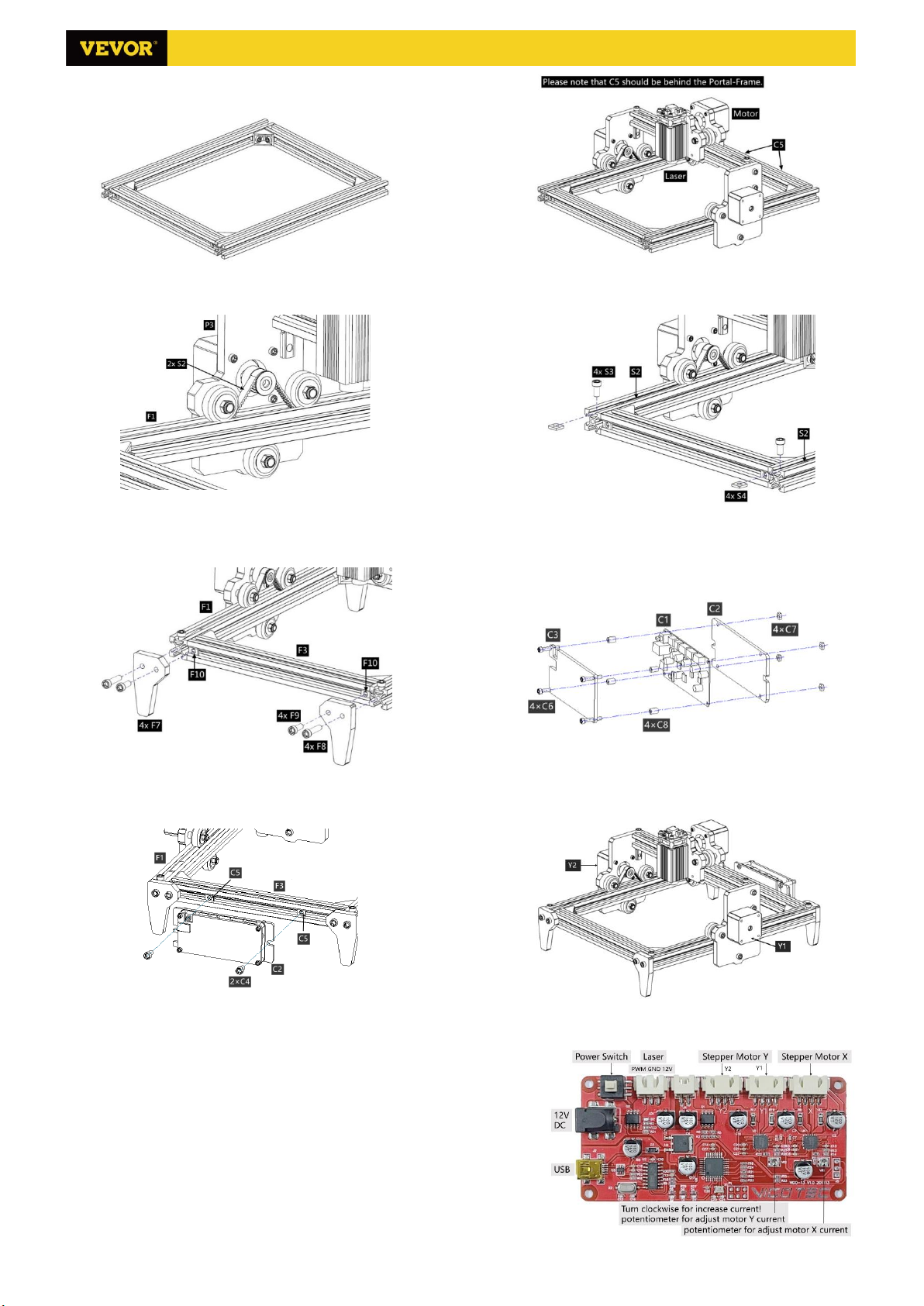
3. Connect Engraving software and laser engraving machine
After turning on the machine by pressing the power key on the engraving machine board, connect the engraving
software and laser engraving machine by following methods.
USB-Serial Connection
Connect the USB-Serial cable to both control board and computer. In general, Win10 can automatically identify
the device While Win7 or other OS may need to install driver manually. Double click CH341SER.exe to install the
driver if necessary. Click Connect on top left corner of VevorWorks. The color of title bar will change to blue,
indicating that the connection between software and machine is successful.
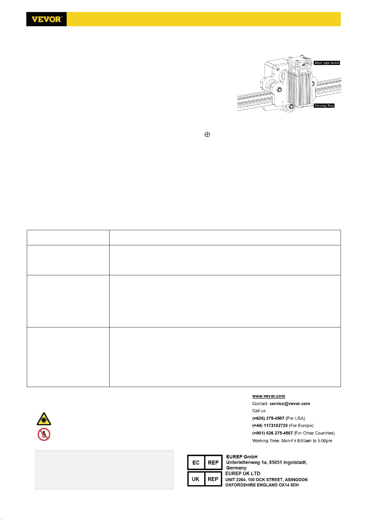
4. Adjust focus
Place the object to be engraved on the lower part of the laser module, the recommended distance is 3-10cm. Click
the weak light button in the upper right corner of the software to turn on the weak light of the laser, then turn
forward and back the focusing ring of the laser module head until the light spot on the surface of the object become
smallest and clearest.
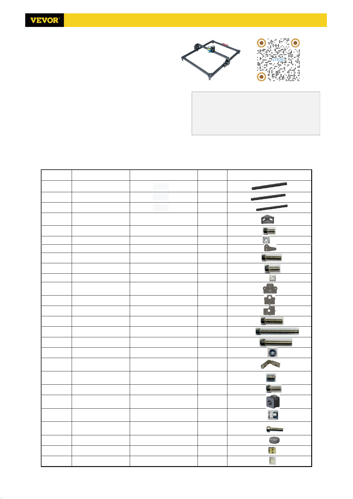
5. Open or input the content to be engraved and adjust the engraving parameters
Engraving content can be opened at the top of the software image or gallery, or edit input text.
Set the start point of engraving and adjust the size of engraving.
Select one of the engraving modes. There are two engraving modes, line mode and point mode, which can
respectively engrave black-and-white images, grayscale images and outlines (only line engraving is supported for
outline, please use outline when cutting objects)
Set engraving parameters. There are four engraving parameters that can be set. These parameters will affect the
engraving speed and engraving effect. It is necessary for you to understand the function of these parameters and
adjust them according to different engraving materials and contents.
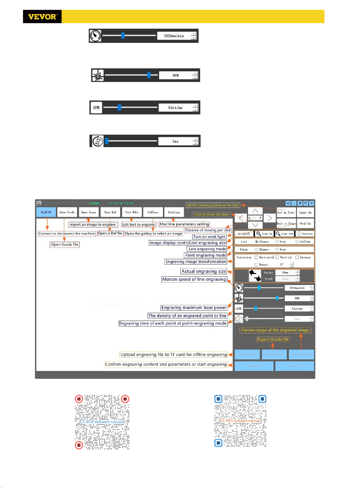
(1) Line engraving speed: Set the engraving speed (only valid for line engraving mode). Note that the set speed
may not be reached when the image is too small or the dot distance is too dense.
L4050 V3.7

2/2
(2) Maximum laser power: Set the maximum laser power, which is the laser power when the maximum gray level
(i.e. all black) in the dot matrix gray mode and line scan gray mode and the laser power in the Binary (black and
white) engraving mode. The unit is the percentage of the installed laser full power.
(3) Engraving point distance: set the precision of dot matrix engraving or line scanning engraving, and the number
of lines or points per millimeter.
(4) Time of dot engraving: Set the engraving time of each dot. The unit is millisecond. According to the power of
the laser module, we generally recommend to set about 1ms to 5ms.
6. Preview the engraving range and start engraving
Click Range preview to confirm the position and range of engraving. Click Start and wait for the engraving to be
completed.
7. Introduction of software interface function
To learn more about the hardware and software features of VG-L5, Please scan the QR code of hardware manual
and software manual at the end of the paper.
Scan to browse software manual Scan to browse hardware manual
Powered by VEVOR 2020
L4050 V3.7

1/5
Hardware Installation Manual
Model:VG-L5 (4050)
Overall Size:650×587×193mm(L×W×H)
Work Area:500×400mm(L×W)
Statement
Original instructions for VG-L5 (4050),Please read all
manual instructions carefully before operating. VEVOR
reserves clear interpretation of our user manual. The
appearance of the product shall be subject to the product you
received. Please forgive us that we won't inform you again if
there is any technology or software updates on our product.
1. Parts list
Part list of VG-L5 Kits
Part No
Part Name
Explanation
Quantity
Picture
F1
620m Aluminum profile
2020, length 620mm
2
F2
513 Aluminum profile
2020, length 513mm
1
F3
470 Aluminum profile
2020, length 470mm
2
F4
Right angle connector
2028
4
F5
Inner hexagon screw
M5×8
8
F6
Trapezoidal Nut
M5
8
F7
Leg
Acrylic
4
F8
Inner hexagon screw
M5×20
4
F9
Inner hexagon screw
M5×12
4
F10
Square Nut
M5
4
P1
Acrylic plate A for X-Part
(for laser)
PMMA, (for laser)
1
P2
Acrylic plate B for X-Part
PMMA, (for stepper motor)
1
P3
Acrylic plate for Y-Part
PMMA
2
P4
Inner hexagon screw
M5×20
2
P5
Inner hexagon screw
M5×50
2
P6
Inner hexagon screw
M5×30
7
P7
Non-slip Nut
M5
9
P8
L connector for
Portal-Frame
L Shape
2
P9
Set Screw for L
connector
M5x6
2
P10
Inner hexagon screw
M5×12
2
M1
Stepper motor
42HD
3
M2
Synchronous pulley and
Set screw
2GT,20 tooth,
Inner diameter 5mm
3
M3
Inner hexagon screw
M3×10
(For Stepper motor)
12
W1
Flat pulley
Φ24×11
9
W2
Column
CU,M5×8
2
W3
Column
PA,M5×6
9
Scan for assembly Videos and guides
Manufacturer:
Kunshan Boye Electronic Technology Co., Ltd
Address:
Room 4, No. 777, Jimingtang South Road, Huaqiao
Town, Kunshan City, Jiangsu Province, China
L4050 V3.7

2/5
S1
600mm Synchronous
belt
X-axis
1
S2
700mm Synchronous
belt
Y-axis
2
S3
Inner hexagon screw
M5×8
6
S4
Square Nut
M5
6
S5
Inner Hexagon Wrench
2/2.5/4mm
1 Set
S6
Nut Wrench
8#
1
S7
Stepper Motor wire
4P,length 1m
3
/
S8
Hardware installation
manual
——
1
/
S9
Control board package
VIGO-13
1 Set
/
S10
USB cable
——
1
/
S11
Laser kit
Optional
1
/
S12
Protective glass
——
1
S13
Power supply
and power line
Optional
1
S14
Gum-elastic pad
——
1
/
Control board package (C4/C5 in the machine kit screw pack)
Part No
Part Name
Explanation
Quantity
Picture
C1
Control board
VIGO-13
1
C2
Acrylic plate for control board A
3mm
1
C3
Acrylic plate for control board A
3mm
1
C4
Inner hexagon screw
M5×8
2
C5
Square Nut
M5
2
C6
Inner hexagon screw
M3×18
4
C7
Nut
M3
4
C8
Column
PA, M3×7
4
Laser package(Optional)
Part No
Part Name
Explanation
Quantity
Picture
L1
Laser kit
Optional
1
/
L2
Inner hexagon screw
M3×12
2
L3
Laser wire
3P,DX85
1
/
2. Assembly
Please read the following assembly instructions and control board instructions carefully, and pay attention to the
sequence of assembly. Please refer to the shape of the actual parts purchased.
1. Assemble Laser L1 (Optional) and P1.
2. Assemble M1, M2 and P2.
L4050 V3.7

3/5
3. Assemble P2, P3, W1 and W2.
4. Assembly completed. This part is named X-Part.
5. Slide F2 into X-Part. And pass S1 through the synchronous pulley and the
Flat pulley as shown in the figure.
6. Fix the belt at the starting point with S4 and N2 first. Tighten up the belt
and fix it on the other side with S4 and N2.
7. Assemble M1, M2 and P3. Assemble 2 sets symmetrically.
8. Assemble W1 and W3 to P3. Assemble 2 sets symmetrically. This part is
named Y-Part.
9. Assemble 2 sets of Y-Part to F2. Please note that the motor on X-Part and
synchronous belt should be below F2. And also note that the laser on
X-Part and the motor on Y-Part are on the same side of F2.
10. Assembly completed. This part is named Portal-Frame.
11. The preassembly position of the framework components is shown in the
figure. Please note that F6, F10, and C5 should slide into the side grooves
of the profiles as shown in the figure in advance.
12. Connect F1 and F3 with F4 and F5. Please notice the flatness of the
whole framework. It is recommended to preposition all F4 and F5 first. Lay
the frame flat on a flat surface and then tighten the screw in turn.
L4050 V3.7

4/5
13. Assembly completed. This part is named Lower-Frame. Please notice
again whether F10 and C5 are in the correct position of the groove.
14. Slide the Portal-Frame onto the slide of the Lower-Frame. Please note
that C5 should be behind the Portal-Frame.
15. Assemble 2 sets of S2. Pass S2 through the synchronous pulley and the
Flat pulley as shown in the figure.
16. Fix S2 at the starting point with S4 and N2 first. Then tighten up the belt
and fix it on the other side with S4 and N2.
17. Assemble 4 sets of Acrylic legs F7.
18. Assemble Control board C1 (Optional) and C2, C3. This part is named
Control-Part.
19. Assemble the Control-Part to the rear profiles F3.
20. Final assembly completed.
3. Control-Board and Laser
3.1 Instructions for control board (Optional)
The Motor-X and Motor-Y interface on board should be
connected to the X-Part and Y-part motors correspondingly. The two
Y-Part motors can be connected to any of the two Motor-Y interfaces
on board. It's only related to the direction of motion, and users can
change the direction of Y in the software Settings. The 6Pin of the
motor wire is for the motor, and the 4Pin is for the control panel.
Please connect the laser to the control board with the 3pin wire.
L4050 V3.7

5/5
Connect to the power supply and the computer by USB.
In general, there is no need to adjust the motor drive current.
Please focus the laser on the materials to be carved referring to the laser instructions below before starting carving.
3.3 Instructions for laser (Optional).
Please wear the protective glasses before operating the laser!
When all the connections are completed, turn on the power, and the laser
is standby for working. The red light on the top of the laser is continuous
lighting in this time.
Turn on the weak light and adjust the focal length (except the
Fixed-Focus Laser)
Please lay the materials to be carved flat under the laser. The recommended distance from laser outlet to materials
is 3~10cm. Out of range may be out of focus.
Press the weak light switch on the top of the laser (Marked as ). Then the red light will flash and the weak light
on. Laser spots can be seen on the materials to be engraved at this time. Rotate the focusing ring slowly on the laser
outlet to shrink the laser spots. When the laser spots are minimized, it is the optimum state for laser engraving.
After that, press the weak light switch again, and the weak light is turned off. The red light on the top of the laser is
continuous lighting in this time, and the laser is standby for working.
It is important to understand that this weak light switch on the top of the laser is not controlled by control software.
So be sure to switch back to normal (make sure that weak light is off) before you start engraving.
4. Notice and FAQ
(1).Please pay attention to the sequence of the installation steps to avoid repeated disassembly.
(2). It is strictly prohibited to use this machine unattended.
(3). Make sure to wear protective glasses before operating the laser.
FAQ
The control software cannot
be opened
Please check whether the system is Win7 or above.
Wrong control respond
Please power off the device and shut down the software, then restart both. If
useless, please try below.
Please restore the device by click Restore in setting, then click Model Select and
choose the device you used to reset parameters.
The carving is not good or
there is no burned trace
Please check whether the focal length of laser is in the recommended distance.
Please check whether the laser focus is at a minimum.
Please check whether the object to be caved is laid flat.
Please check whether the laser is in weak light mode.
Please check whether the power indicator light on the control panel is
continuous lighting.
Please check whether the motors are working properly.
The stepper motors are not
working properly
Please check whether the connection between the three motors and control
board is correct.
Please check for any irrelevant stuff on the slide to block movement.
Please check whether the motor drive current is normal. Too little current causes
the motors to stall. Too much current makes the motors to vibrate, and causes the
movement of the machine or materials to be carved.
Please check whether the power indicator light on the control panel is
continuous lighting.
Important Safety Instruction
Warning: To reduce the risk of burns, electrocutions, or injury to persons!
Strictly prohibit laser radiation of the eyes!
Strictly prohibit watching laser without wearing protective glasses!
Strictly prohibit using by children!
Strictly prohibit using this machine unattended!
Powered by VEVOR 2022.
EU Importer: WAITCHX
Address: 250 bis boulevard Saint-Germain 75007 Paris
UK Importer: FREE MOOD LTD
Address: 2 Holywell Lane, London, England, EC2A 3ET
L4050 V3.7
This manual suits for next models
1
Table of contents
Other VEVOR Printer manuals

VEVOR
VEVOR S3018 Prover User manual

VEVOR
VEVOR S3020 User manual

VEVOR
VEVOR PD150 User manual

VEVOR
VEVOR 3020 User manual

VEVOR
VEVOR NS101-M User manual

VEVOR
VEVOR KH-5030 User manual

VEVOR
VEVOR L4040 User manual

VEVOR
VEVOR S3018 Prover User manual

VEVOR
VEVOR S3018 Pro User manual

VEVOR
VEVOR S1610 User manual