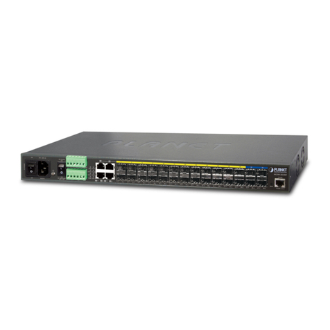
Advantage-Devices W900iMt User manual

W900iMT
WirelessEthernet
Bridge
Revision C November 4, 2010
Document Part Number GC-800-325c
Advantage-Lab GmbH www.advantage-devices.com
Otto-Röhm-Strasse 69 info@ advantage-lab.com
64293 Darmstadt / Germany v1

2
W900iTR User Guide
Copyright and Trademark
Copyright 2010, Advantage-devices. All rights reserved.
No part of this manual may be reproduced or transmitted in any form for any purpose other than the
purchaser's personal use, without the express written permission of Advantage-devices. Advantage-
devices has made every effort to provide complete details about the product in this manual, but
makes no warranty of any kind with regard to this material, including, but not limited to, the implied
warranties of merchantability or fitness for a particular purpose. In no event shall Advantage-
devices.
be liable for any incidental, special, indirect, or consequential damages whatsoever included
but not
limited to lost profits arising out of errors or omissions in this manual or the information
contained
herein.
Advantage-devices. products are not designed, intended, authorized or warranted for use as
components in systems intended for surgical implant into the body, or in other applications intended
to support or sustain life, or in any other application in which the failure of a Advantage-devices.
product could create a situation where personal injury, death, or severe property or environmental
damage may occur. Advantage-devices. reserves the right to discontinue or make changes to its
products at any time without notice.
Advantage-devices and the Advantage-devices logo, and combinations thereof are registered
trademarks of Advantage-devices. DSTni is a trademark of Lantronix, Inc. All other product names,
company names,
logos or other designations mentioned herein are trademarks of their respective
owners.
W900IM is a trademark of Advantage-devices. Ethernet is a trademark of XEROX
Corporation.
Windows 95, Windows 98, Windows 2000, Windows NT, and Windows XP are
trademarks of
Microsoft Corp. Netscape is a trademark of Netscape Communications
Corporation.
Advantage-Devices
Otto-Röhm-Strasse 69
64293 Darmstadt, Germany
Phone:+49 6151 6294871
Technical Support
Phone:+49 6151 6294871
Fax:+49 6151 817329
On-line:www.Advantage-Devices.com

W900iTR User Guide
i
Disclaimer and Revisions
Operation of this equipment in a residential area is likely to cause interference in which case the
user, at his or her own expense, will be required to take whatever measures may be required to
correct the interference.
Attention: This product has been designed to comply with the limits for a Class B digital
device pursuant to Part 15 of FCC Rules. These limits are designed to provide reasonable
protection against harmful interference in a residential installation. This equipment
generates, uses, and can radiate radio frequency energy, and if not installed and used in
accordance with this guide, may cause harmful interference to radio communications.
Changes or modifications to this device not explicitly approved by Advantage-devices will void the
user's
authority to operate this device.
The information in this guide may change without notice. The manufacturer assumes no
responsibility for any errors that may appear in this guide.
Date
Rev.
Author
Comments
07/11/08
A
GR
Preliminary Release
09/09/08
B
GR
Correction to power jack label
10/04/10
C
GR
New MTR modules, correct part name


W900iTR User Guide
3
Compliance Statement (Part 15.19)
This device complies with Part 15 of the FCC Rules. Operation is subject to the following two
conditions:
This device may not cause harmful interference.
This device must accept any interference received, including interference that may cause
undesiredoperation.
Warning (Part 15.21)
Changes or modifications not expressly approved by the party responsible for compliance could void
the user’s authority to operate the equipment.
RF Exposure (OET Bulletin 65)
To comply with FCC RF exposure requirements for mobile transmitting devices, this transmitter
should only be used or installed at locations where there is at least 20cm separation distance between
the antenna and all persons, and must not be co-located or operating in conjunction with any other
antenna or transmitter.
Information to the User –Part 15.105(b)
Note: This equipment has been tested and found to comply with the limits for a Class B digital
device, pursuant to part 15 of the FCC Rules. These limits are designed to provide reasonable
protection against harmful interference in a residential installation. This equipment generates, uses
and can radiate radio frequency energy and, if not installed and used in accordance with the
instructions, may cause harmful interference to radio communications. However, there is no
guarantee that interference will not occur in a particular installation. If this equipment does cause
harmful interference to radio or television reception, which can be determined by turning the
equipment off and on, the user is encouraged to try to correct the interference by one or more of the
followingmeasures:
Reorient or relocate the receiving antenna.
Increase the separation between the equipment and receiver.
Connect the equipment into an outlet on a circuit different from that to which the receiver is
connected.
Consult the dealer or an experienced radio/TV technician for help.

4
W900iTR User Guide
Warranty
Advantage-devices warrants each product to be free from defects in material and workmanship for a
period of ONE YEAR after the date of shipment. During this period, if a customer is unable to
resolve a product problem with Advantage-devices Technical Support, a Return Material
Authorization
(RMA) will be issued. Following receipt of a RMA number, the customer shall return
the product to
Advantage-devices, freight prepaid. Upon verification of warranty, Advantage-
devices will -- at its option --
repair or replace the product and return it to the customer freight
prepaid. If the product is not under
warranty, the customer may have Advantage-devices repair the
unit on a fee basis or return it. No services
are handled at the customer's site under this warranty.
This warranty is voided if the customer uses
the product in an unauthorized or improper way, or in
an environment for which it was not designed.
Advantage-devices warrants the media containing software and technical information to be free
from
defects and warrants that the software will operate substantially for a period of 60 DAYS
after the
date of shipment.
In no event will Advantage-devices be responsible to the user in contract, in tort (including
negligence),
strict liability or otherwise for any special, indirect, incidental or consequential damage
or loss of
equipment, plant or power system, cost of capital, loss of profits or revenues, cost of
replacement
power, additional expenses in the use of existing software, hardware, equipment or
facilities, or
claims against the user by its employees or customers resulting from the use of the
information,
recommendations, descriptions and safety notations supplied by Advantage-devices.
Advantage-devices liability
is limited (at its election) to:
1)
refund of buyer's purchase price for such affected products (without interest)
2)
repair or replacement of such products, provided that the buyer follows the above procedures.
There are no understandings, agreements, representations or warranties, expressed or implied,
including warranties of merchantability or fitness for a particular purpose, other than those
specifically set out above or by any existing contract between the parties. The contents of this
document shall not become part of or modify any prior or existing agreement, commitment or
relationship.

W900iTR User Guide
5
Contents
Table of Contents
1.
Overview........................................................................................................................... 1-1
1.1
Features................................................................................................................1-1
1.2
Range...................................................................................................................1-2
1.3
Operation.............................................................................................................1-3
1.4
SystemDiagram...................................................................................................1-4
1.5
SystemComponents.............................................................................................1-5
1.5.1
AW2Antenna ......................................................................................1-5
1.5.2
AW5POutdoorOmni-DirectionAntenna.............................................1-5
1.5.3
AW11OutdoorAntenna.......................................................................1-6
1.5.4
AW15OutdoorAntenna.......................................................................1-6
1.5.5
AWRF10AntennaCable......................................................................1-7
1.5.6
AWXPM..............................................................................................1-7
1.5.7
PowerSupply.......................................................................................1-8
1.5.8
EthernetConnection.............................................................................1-8
1.5.9
SwitchSettings.....................................................................................1-8
1.6
FrontPanelLEDDisplay....................................................................................1-10
1.7
DigitalSetup ......................................................................................................1-11
1.8
TechnicalSpecifications....................................................................................1-15
1.9
OldMethod........................................................................................................1-15
1.9.1
ToaddNEWsubscriberunitstotheaccesspoint.......................................................1-16
1.9.2
Tore-keyasubscriberunittoaNEWaccesspoint .....................................................1-17
List of Figures
Figure1-SystemDiagram,Point-to-Point ...............................................................................1-4
Figure2-IndoorMultipointSystem.........................................................................................1-4
Figure3-AW2Antenna...........................................................................................................1-5
Figure4-AW15AntennawithAWXPMMountingKit ............................................................1-7
Figure5-Power Connector ......................................................................................................1-8
Figure 6-SwitchSettings .........................................................................................................1-8
Figure7-LEDDisplay...........................................................................................................1-10
List of Tables
Table1-ChannelSelection ......................................................................................................1-9


W900iTR User Guide
1-1
1.
Overview
The W900iMTR allows you to build your own long-range, non-line-of-sight, point-to-point or point-to-
multipoint wireless Ethernet solution that can enable fringe Ethernet devices, including SCADA clients, bio-
scanners, printers, PCs, VoIP phones, point-of-sale devices, digital signage, or Internet kiosks. Each access
point can have up to 16 subscribers. The latest version is now IP addressable and POE enabled.
The W900iMTR solution offers the ideal combination of price, range, data rate, security, interference
avoidance, quality-of-service, and ease-of-use.
1.1
Features
Built-in spectrum analyzer
128 bit AES Encryption, FIPS 197/NIST Certified
Remote diagnostics, link analysis and firmware upgrades via built-in browser interface.
High RF output power provides maximum foliage or wall penetration
Range of 40 miles LOS with 15 dBi antenna
1.536 Mb/s RF Transmission Rate
Ethernet throughput of 935Kb/s
+21 dBm (4 Watts EIRP used with 15 dBi antenna)
Radio Link Budget 148 dB with 15 dBi antenna
Simple plug and play —minimal user programming required
Radio can be configured as an access point or subscriber client
Install up to 16 clients per access point
Can operate up to 12 access points, each on its own non-overlapping channel
Does not require an FCC license to operate or install
Channel selection with DIP switch or via Web browser interface
Power over Ethernet at 9-48VDC, pins 4/5 positive and7/8 ground or use separate power jack.

1-2
W900iTR User Guide
1.2
Range

W900iTR User Guide
1-3
1.3
Operation
The W900iMTR Radio allows the user to create a long-range, wireless Ethernet network with up to 16
subscriber units per access point. The configuration may include any combination of AW900MTR,
AW900XTR and AW900XTP radios. (Please note that older AvaLAN 900 MHz radios can exist on the
same LAN but cannot be used to form wireless links with the AW900MTR/XTR/XTP units because link
encryption protocols have changed.)
Configuring a wireless link with the AW900MTR requires the establishment of six elements:
Each radio must know whether it is to be an access point (AP) or subscriber unit (SU).
Each radio must have an IP address that is unique among all others on the same network.
The AP must know how many SUs are expecting communication with it.
The AP and any given SU must agree on which radio frequency channel they are using. This can be
manually set or allowed to change automatically.
The SU must be assigned a unique subscriber ID to specify which time division slot it will use
when communicating with the AP.
The AP and any given SU must share a common 128-bit encryption key.
AW900MTR radios may be configured by two different methods. They may be connected to a computer
that will run a web browser, setting parameters via their built-in browser interfaces. They may also be
programmed via the older “easy key” method using the DIP switches and LEDs on the module.
If you wish to use the older method, go to the Old Method section and follow the procedures there.
The access point (AP) automatically scans for the best of the 12 available radio frequency channels,
encrypts Ethernet data received from the network, and transmits it wirelessly to the correct subscriber unit
(SU). The AP is constantly monitoring the radio link and can automatically change the channel if
performance is degraded due to interference. If two AP units are very close to one another, they may
interfere if operating on adjacent frequency channels. Place them at least 10 feet apart or manually select
non-adjacent channels for their operation. Also, the SU should be placed at least 10 feet from the AP to
avoid overloading the radio’s receiver.
Any 10/100 BaseT Ethernet client device (ECD) can be connected to an AW900MTR subscriber unit. Each
SU encrypts Ethernet traffic received from the attached ECD and transmits the data wirelessly to its AP.
Each SU can be plugged directly into an ECD without adding drivers or loading software. Essentially, once
the AP/SU pair is configured and running it behaves like a continuous Ethernet cable.

1-4
W900iTR User Guide
1.4
System Diagram
The following diagram shows a basic configuration of an Access Point and Client (subscriber). Ethernet
data flows across the 900MHz radio link almost like a direct link of CAT5 cable.
900MHz Radio
Ethernet Ethernet
Access Point Client
Figure 1-System Diagram, Point-to-Point
Figure 2-Indoor Multipoint System

W900iTR User Guide
1-5
1.5
System Components
Each system can have different hardware configurations, based on system needs. This section shows
different antennas and options.
1.5.1
AW2 Antenna
The units shown in Figure 1 have an AW2 antenna installed.
Figure 3-AW2 Antenna
Other antenna options are available for longer range and outdoor operation.
1.5.2
AW5P Outdoor Omni-Direction Antenna
The AW5P 5dBi omni-direction 900 MHz antenna, is designed for pole mounting, and is recommended for
fixed base station applications. If you use a long range antenna, connect the cable to the antenna jack on the
top of the unit. The jack is a Female RPTNC.

1-6
W900iTR User Guide
1.5.3
AW11 Outdoor Antenna
The AW11 is an 11dBi high gain directional 900MHz antenna. The package includes: one (1) antenna and
wall mounting bracket, DC grounded [includes 10in RPTNC pigtail].
Note: You must order a cable that will reach from the GC-W900-IM to the outdoor mounting point. For example, the
AWRF10 is a ten foot cable with the proper connectors for the radio and antenna.
Specifications:
Frequency Range 800-960MHz
Nominal Impedance 50 Ohms
Gain 11dBi at 915MHz
VSWR <1:8
F/B ratio >15dB
Max input power 6W
Material of boom/elements Aluminum
Dimensions 21x6.8x1.575in (535x175x40mm)
Weight 0.528lbs (240g)
Max wind speed 100mph
Temperature -40F to 158F (-40C to 70C)
1.5.4
AW15 Outdoor Antenna
The AW15 is a 15dBi high gain directional 900MHz antenna. The kit includes: one (1) antenna and wall
mounting bracket, DC grounded [includes 10in. RPTNC pigtail].
Note: You must order a cable that will reach from the GC-W900-IM to the outdoor mounting point. For example, the
AWRF10 is a ten foot cable with the proper connectors for the radio and antenna.
Specifications:
Frequency Range: 800-960MHz
Nominal Impedance: 50 Ohms
Gain: 15dBi at 915MHz
VSWR: <2:1
F/B ratio: >20dB
Max input power: 6W
Material of boom/elements: Aluminum
Dimensions: 39.5x16.5x16.1in (1005x420x410mm)
Weight: 2.1lbs (950g)
Max wind speed: 65mph
Temperature: -40F to 158F (-40C to 70C)

W900iTR User Guide
1-7
1.5.5
AWRF10 Antenna Cable
The AWRF10 is a high quality 10 foot RF Extension cable made from LMR400 RF Cable and assembled
with an RPTNC male on one end (Radio) and a FME connector (Antenna) on the other. This extension cable
allows you to locate your radio up to 10 feet from the antenna. LMR400 is a high quality, standards based,
low-loss cable for use with high gain antennas. The AWRF10 has an RPTNC male (jack) and FME
connector (plug) on either end for easy installation with the AW15 or the AW11 antennas. Other size cables
available.
1.5.6
AWXPM
The AWXPM is a pole mount kit that contains all the hardware needed to mount a long range Yagi style
antenna on a pole. An AW15 or AW11 antenna can be mounted directly to the large aluminum plate, which
is secured to a pole with two U-bolts. The kit includes one (1) pole mounting plate, two (2) pole u-bolts for
mounting the plate on up to a 2” pipe, and two (2) antenna u-bolts for mounting an antenna onto the
mountingplate.
Figure 4-AW15 Antenna with AWXPM Mounting Kit

1-8
W900iTR User Guide
1.5.7
Power Supply
The power supply shipped with the unit will supply 8-24VDC. If you supply your own power, make sure
you connect the wires from the power supply to the power connector correctly. Note the markings on the
power jack located on the bottom of the unit. You can also use a POE enabled switch to power the unit
through the Ethernet cable.
Caution: Do not use POE if you have a power supply connected to the power jack.
Figure 5-Power Connector
1.5.8
EthernetConnection
Connect a CAT5 Ethernet cable to the Ethernet jack located on the bottom of the unit. See Figure 5.
1.5.9
Switch Settings
You can now configure a W900iMTR using a web browser. The switches are not needed if you configure
the units with a web browser.
Figure 6-Switch Settings
DIP SW 1
Access point or subscriber unit
By selecting DIP 1 ON the radio wilt operate as an access point
By selecting DIP 1 OFF the radio will operate as a subscriber unit
DIP SW 3-8
Automatic frequency selection mode (DIP switches - DIP 3·8 OFF for automatic mode)
The GC-W900-IM is designed to automatically select and continuously optimize the performance
of its radio channel. The radio channel is monitored to ensure it is providing low error rates
necessary for successful data transmission. In the event that the error rate rises, the access point
will autonomously change to a new channel. There are 12 non-overlapping channels.

W900iTR User Guide
1-9
Manual frequency selection mode
The operation of the GC-W900-IM can be restricted to a specific channel within the 900 MHz band
by setting DIP switches 1-8 on the access point as shown in Table 1-Channel Selection. The
subscriber unit responds to the access point's choice of channel and its DIP switches have no effect
and do not need to be selected.
Channel
SwitchSetting
CenterFrequency
1
3 On/4 Off/5 Off/6 Off
903.12500MHz
2
3 Off/4 On/5 Off/6 Off
905.20833MHz
3
3 On/4 On/5 Off/6 Off
907.29167MHz
4
3 Off/4 Off/5 On/6 Off
909.37500MHz
5
3 On/4 Off/5 On/6 Off
911.45833MHz
6
3 Off/4 On/5 On/6 Off
913.54167MHz
7
3 On/4 On/5 On/6 Off
915.62500MHz
8
3 Off/4 Off/5 Off/6 On
917.70833MHz
9
3 On/4 Off/5 Off/6 On
919.79167MHz
10
3 Off/4 On/5 Off/6 On
921.87500MHz
11
3 On/4 On/5 Off/6 On
923.95833MHz
12
3 Off/4 Off/5 On/6 On
926.04167MHz
Table 1-Channel Selection
Note: The channel chart can be found on the side of the case.

1-10
W900iTR User Guide
1.6
Front Panel LED Display
LEDs on the front panel show the operational status of the unit.
Figure 7-LED Display
Name
Function
Color
Power
Unit has power and has successfully booted.
Green
RF TX
Radio Transmission is occurring.
Green
RF RX
Radio reception is occurring.
Green
Ethernet Link
The Ethernet Port has a valid Ethernet connection.
Green
CHN: 1
By adding the channel numbers that are lit the user
can determine the current radio channel.
Green
CHN: 2
CHN: 4
CHN: 8
CHN: 16
CHN: 32
Link Quality Meter
or
Key Exchange Mode
when blinking
sequentially.
Excellent Quality, no retransmissions
Green
Very good quality, few retransmissions
Green
Good quality, occasional retransmissions
Amber
Fair quality, some retransmissions
Amber
Poor quality, many retransmissions
Red
No link
Red

W900iTR User Guide
1-11
1.7
Digital Setup
1.
Digital configuration is done by means of the W900iMTR’s built in browser interface. It should be
powered on and connected at least temporarily to a network containing a computer that can run a
conventional web browser.
2.
Copy the ipfinder.exe from the CD, placing it on your desktop or in a convenient folder. You can also
download the file from:
http://www.avalanwireless.com/ipfinder/ipfinder.zip
Note that this utility only runs on MS Windows, not linux or MAC. If you must use a non- Windows
computer for configuration, make sure your subnet mask allows your computer to see 192.168.17.17.
Connect to that default IP address with your web browser, continuing the setup procedure with step 6.
3.
Run the IP Discovery Utility, ipfinder.exe and you should see a window similar to this:
The AW900MTR should appear in the list at the default IP address of 192.168.17.17. If it does not, click
“Search” to regenerate the list. If it still does not appear, you have a connection issue and need to re-
examine the cabling or you may have a firewall issue on your computer.

1-12
W900iTR User Guide
4.
Double click the list item that refers to the AW900MTR being configured. You should see a second
window that is similar to this:
The information on the left is the current status of the radio, while the boxes on the right allow you to
change it. It is important that the IP address of the W900iMTR is in the same subnet as your computer. For
example, if the subnet mask is 255.255.255.0 ( a class C network), the first three number groups of the IP
address must match. Choose your desired parameters and click “Apply.”
5.
Make note of the chosen IP address and password, then click “Go to Device Web Page.” This will cause
your default web browser to launch with the device IP address in the browser address bar. Or you may
launch the browser on your own and enter the web page address manually: http://[the IP address you just
set].
Table of contents

