Advantech PWS-1419T User manual
Industrial
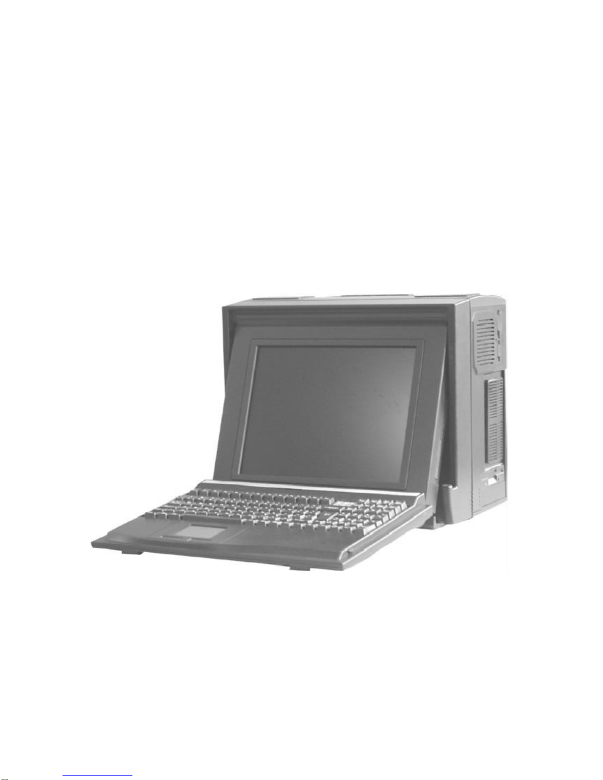
PWS-1419T
PortableComputer
SystemAssemblyGuide
ATechnicalGuideforSystemIntegrators
and Service Technicians

Theinformation containedinthisdocumentisbelievedtobe
accurate.However,no responsibilityisassumedforitsuse,
norforanyinfringementsofpatentsorotherrightsofthird
partywhichmay resultfromitsuse.Thisinformationissub-
jecttochangewithoutanynotice.

Specification 4
BeforeYou Start5
Precautions5
PowerConnections5
Non-Autosensing PowerSupply5
ATXPowerSwitch5
Ventilation 6
Careforthe LCD 6
Toolsand Supplies Needed6
SubassemblyContents6
PartsContents6
OptionalCDROM7
Identifying Partsand Controls7
Opening the Side Access Covers7
PWA1419TSide Views7
FrontView9
OSD10
TheKeyboard10
GettingStarted

Getting Started
GeneralFeatures
Supportpassivebackplane formfactorplatforms.
ABS plastichousing withaluminuminternalchassis.
14.1”High resolution colormartixTFT LCD display
Built-inanalog todigitalVGAsignalconversion board
Add-on cardretention system.
Shock mountprotection forthe harddisk driver
Detachable104/105-keys keyboard
Built-intouchpad.
Built-inspeakerwithamplifier
200WATorATXpowersupply(optionalDC powersupply)
Carrying casewithwheel.
Environment
Operating temperature:0Cto50C,10-80%humidity
Storage temperature:-20Cto60C,5-95%humidity
Dimensions&Weight
Dimensions:15.7”/399mm (W)
13.2”/335mm(H)
10.4”/264mm (D)
Weight: 18lbsSKD;approx.22lbssystem

BeforeYou Start
The majorcomponentofthe subassemblyisthe chassis,whichcomesintwomodels—9x
ISA slotor4xPCI, 5xISA slotPassiveBackplane.The chassiscomespre-assembled withan
activematrixLCD,LCD controller,powersupply,keyboard,ventilation fansand internal
speaker.Tocompletethe system,you mustadd asystemboard,CPUand peripheraldevices.
Beforeadding thesedevices,itisimportanttofollowcertainbasicsafetyprecautions.You
shouldbecomefamiliarwiththe chassisbothexternallyand internally.And you shouldalso
havethe righttoolsavailabletoyou.
Precautions
PowerConnections
UseSupplied PowerCord
The subassemblyisshipped withapowercordcompatiblewiththe ACwall outletinyour
region.
Non-AutosensingPowerSupply
Beforeplugging inthe powercord,examine the powersupplytosee ifyou havean
autosensing ornon-autosensing powersupply.
Autosensing powersuppliesautomaticallyadjusttothe ACconstructed ofmetaland provide
frontimpactprotection foroutletvoltage.If yoursubassemblyisshipped withanon-
autosensing powersupply,therewill be avoltage selectorswitchlocated nearthe ACpower
connector.Makesureit’s settothe appropriatevoltage setting foryourpoweroutlet.
ATXPowerSwitch
The powersupplyshipped withthe ATXchassismayormaynothavean ON/OFF switch.To
powerup yoursystemwherethe powersupplyhasan ON/OFF switch,you mustfirstpress the
switchtothe ONposition and then press the ATXpowerup/downswitchlocated on the frontto
startyoursystem.
The ATXpowerswitchfound on the frontofthe chassisDOES NOTturnoff the AC
power.ToremoveACpowerfromyoursystem,you mustunplug the ACpower
cordfromthe ACoutletorthe chassis.

Ventilation
The chassiscomeswiththree intakefansand one powersupplyexhaustfan providing
cooling and airflow.When operating the system,neverblock anyventilation openings.Always
leaveenough roomaround the chassistoallowadequateairflow.
CarefortheLCD
The chassiscomeswithapre-assembled activematrixLCD.Liquidcrystaldisplays are
made ofglass whichwill breakorcrack ifmishandled.During systemassembly,keep the
keyboardlatched tothe chassis.The keyboardhousing isconstructed ofmetaland provides
frontimpactprotection forthe LCD during transportation.
ToolsandSupplies Needed
Beforebeginning yourwork,makesureyou havethe following toolsand suppliesavailable:
#2 Phillips(cross head)screwdriver.
Ananti-staticwriststrap (recommended).
SubassemblyContents
The subassemblyconsistsof,
Thissubassemblyguide.
Chassiswithpre-assembled LCD,LCD controller,powersupply,cooling fans,internal
speakerand keyboardwithintegrated pointing device.
Powercord.
Carrycase.
Partsforinstalling motherboardand drives.
See Appendixfortechnicalspecifications.
PartsContents
The subassemblypartskitcontainsthe following hardwareforinstalling boardsand drives.
1.Round head screw2Ö long (for securing CD ROM interface board)
2.Round head screw(forsecuring backplane on the standoff, interfaceboard).
3.Metalwasher(usewiththe flathead and round head screwsformounting the drives)
4. Insulating washer(when installing the motherboarduseitwiththe round head screw4).
5.Flathead screw(forsecuring harddriver).
7.Black flatscrew(forsecuring fan filtercover)
9.MotherboardStandoff
10.Round head screw 2Ö short (for securing slim CD ROM)
12. Flathead screw(forcardstabilizer).
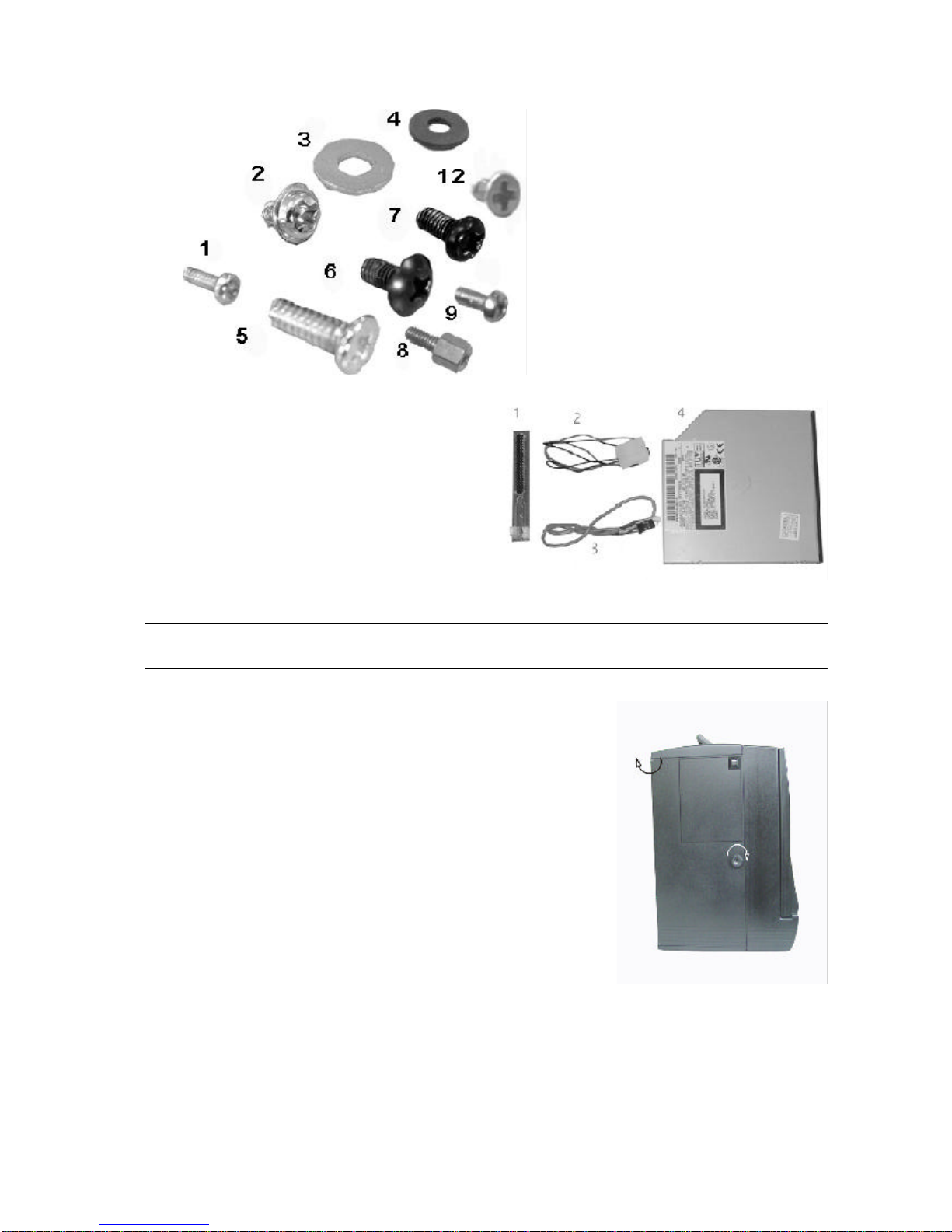
OptionalSlimCD ROMDisk
1.SlimCD ROMinterfaceboard
2.CD ROMpowercable
(interfacetopowersupply)
3.Audiocable
(interfaceboardtosound cardor
SBCAudioout)
4.SlimCD ROM
The pinoutmaybe differentforotherbrand orversion ofCD ROM&floppydisk
Donotusethe CD ROMand floppyfromothersources.
Identifying Partsand Controls
Opening theSideAccess Covers
The side access doorprovide side impactprotection forthe
chassis.The access doormustbe opened toaccess the I/O
connectors.
Turnthe thumbscrewinthe counterclockwisedirection toopen
the access covers.Theyswing outtowardthe back.
PWA1419TSideViews
Usethe photobelowtoidentifycomponentsand I/Oportsthatareaccessiblefromthe two
sidesofthe PWA1419Tchassis.The illustration showsthe externalconnectorsand compo-
nentsofacompletelyassembled SBCsystem.Yoursubassemblyhasonlyknockoutholes
instead.

PWS1419TSideViews
Usethe photobelowtoidentifycomponentsand I/Oportsthatareaccessiblefromthe two
sidesofthe BP-10 chassis.The illustration showsthe externalconnectorsand componentsof
acompletelyassembled SBCsystem.Yoursubassemblyhasonlyknockoutholesinstead.
I/Oport
knockouts.
VGAport&monitor
connector9add-on cardslot
(optional12)
Internalspeaker
connector
ACpowerInputSocket
PowerFan Powerswitch
3intake
fansw/
Filter
Handlebar
resetswitch
3.5”
Floppy
disk.
ATXPowerswitch
Volume
Tone
CDROM
TheCDROMison therightsideofthepanel
The ATXpowerswitchDOES NOTturnoff the ACpower.ToremoveACpowerfromyour
system,you mustunplug the ACpowercordfromthe ACoutletorthe chassis
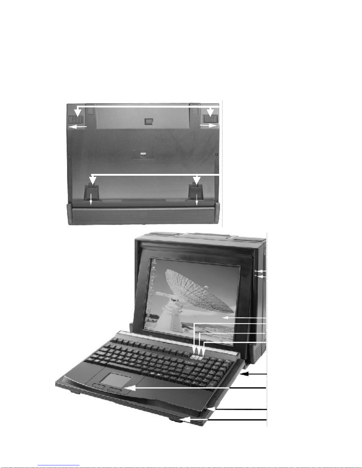
FrontView
PowerLED
HDDLED
TFTLCD
NumLock
Scroll Locck
CapsLocck
LEDIndicator
Touch Pad
Anti-slipper
RubberKnob
Push theKeyboard Latchesto
center
Keyboard
Latches
Pull up thekeyboard stand
You access the frontpanelcontrolsbyfirstdisengaging the keyboard.Disengage the keyboard
fromthe latchesbysliding the latchtabson the bottomsidesofthe keyboardtowardsthe
centerasshownand simultaneouslypull the top partofthe keyboardawayfromthe chassis.
The keyboardisstill hinged on the bottombylatchbolts.Laydownthe keyboard.
Onthe frontside ofthe chassisyou’ll find the following controlsand subassemblyelements:
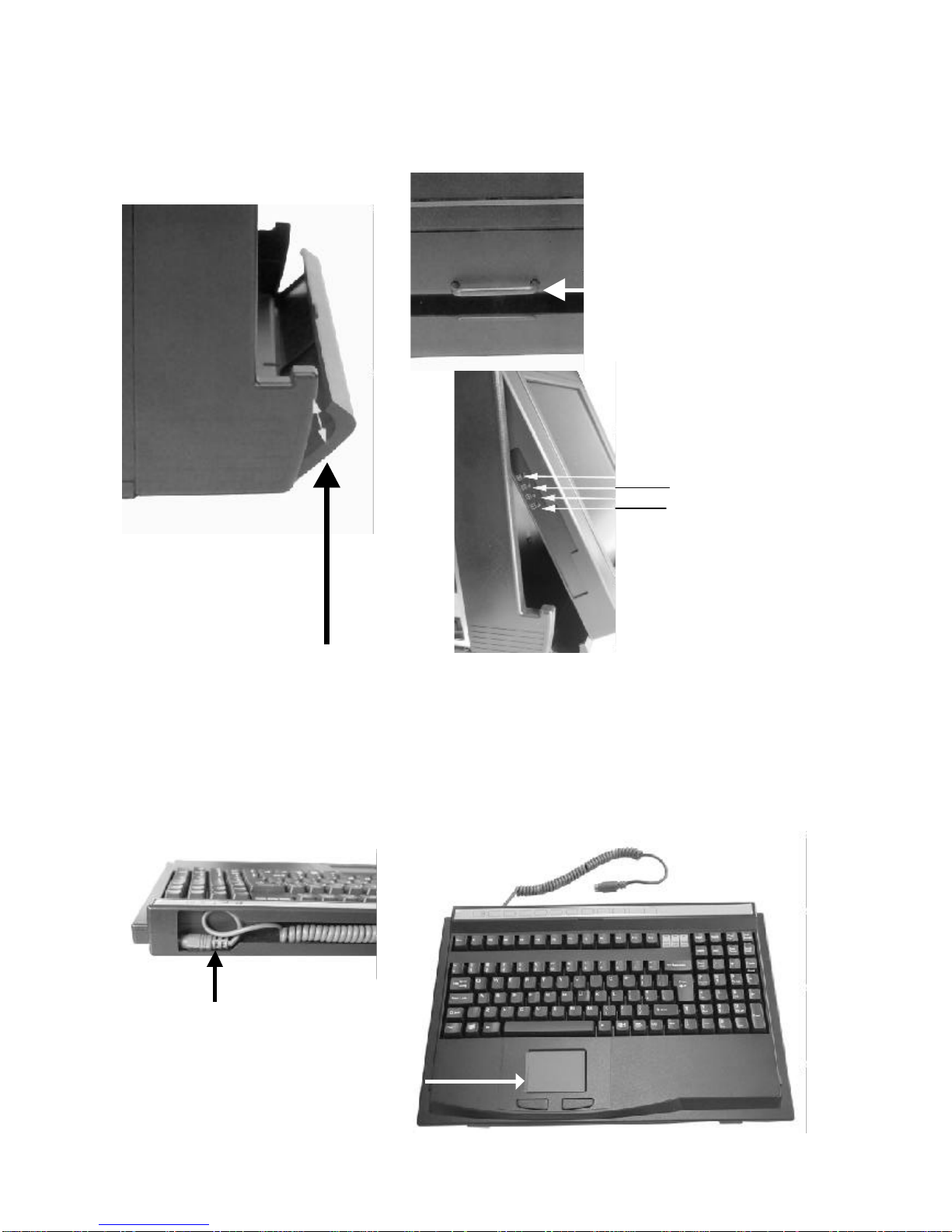
TheKeyboard
The subassemblycomeswithamechanicalswitchkeyboardwithan integrated touchpad
device.The signalcableisconcealinthe fillisterofthe keyboard,you havepull itup tocon-
nectthe connectorofthe SBC.
OSDbutton
TheOSDbutton ison theleftsideofthepanel, you haveto pull up thepanelfirstto see the
buttons, pull down thesmall doorand pull up thepanelwith thesmall baron thepanel.
Small door
Pull up thebar
OSDButtons
“Manual”
“Select”
“+”“-“
The concealed cable
touchpad

1.Opening TheChassis12
Removing the Back Cover12
Removing the CardStabilizers12
Identifying the InternalParts12
Removing the DriveCage 12
Installing the Backplane 13
Installing the Standoffs13
Connecting the PowerConnector15
. Installing the Drivestothe DriveCage 15
. Installing the DriverCage intothe Case17
Installing theSBC 18
Setting yourSBCJumpers18
. Installing the Add-on Cards19
Installing the CardStabilizers19
Preparing toStarttheSystem20
Connecting the Video and InputDevices20
Closing the Back Cover21
PWS-1409T
Openthechassis
Removing theBack Cover
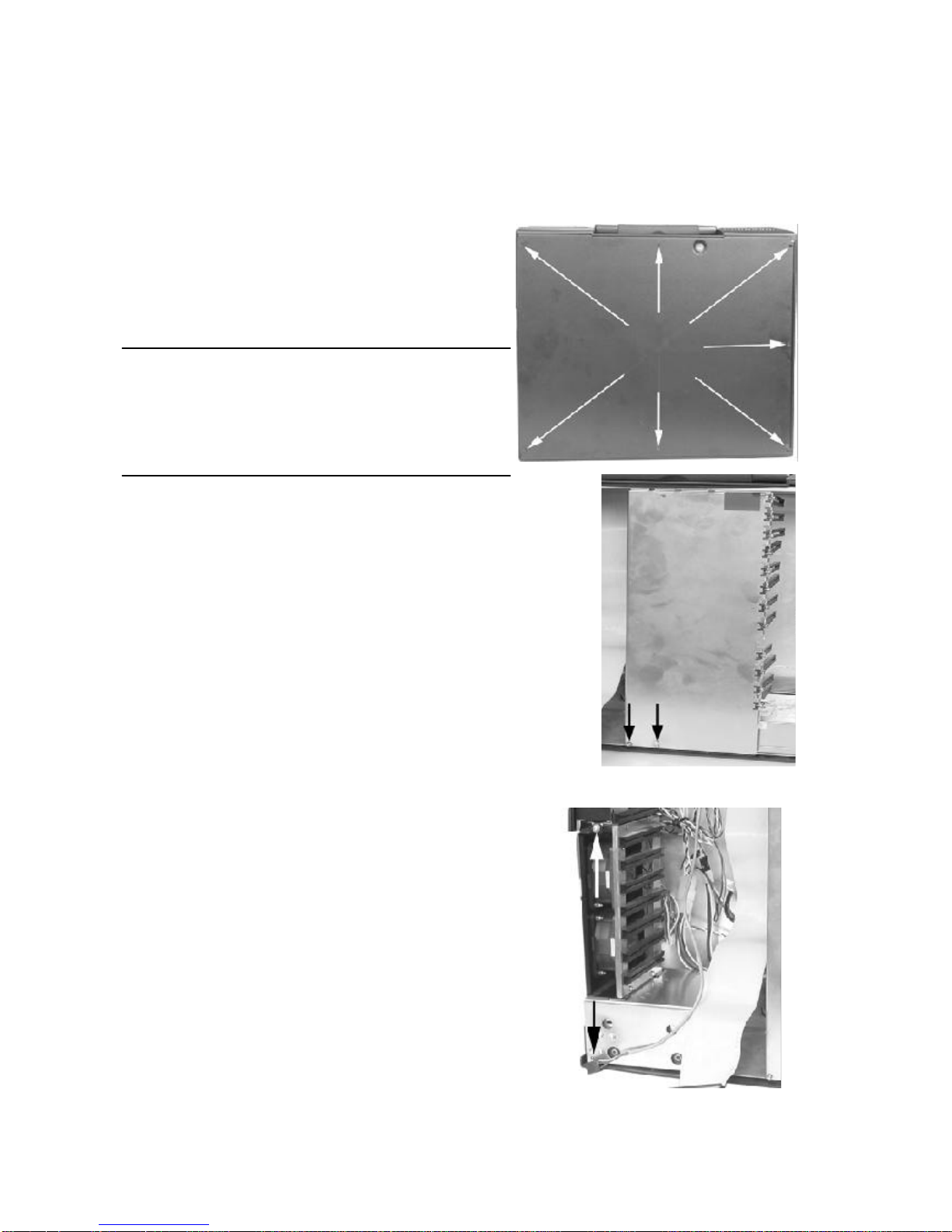
Facethe back ofthe chassis.Removeall screwsasshown.Thereare7screwsalong the
perimeterofthe back coverthatholdsthe back covertothe chassis.
Always powerdownthe system.
Always turnoff anyperipheraldevicesconnected to
the system.
Always unplug the ACpowercordfromthe chassis.
Face the back of the chassis. Remove
all the release screws as shown. There
are 7 screws along the perimeter of the
back cover that secures it to the
chassis.
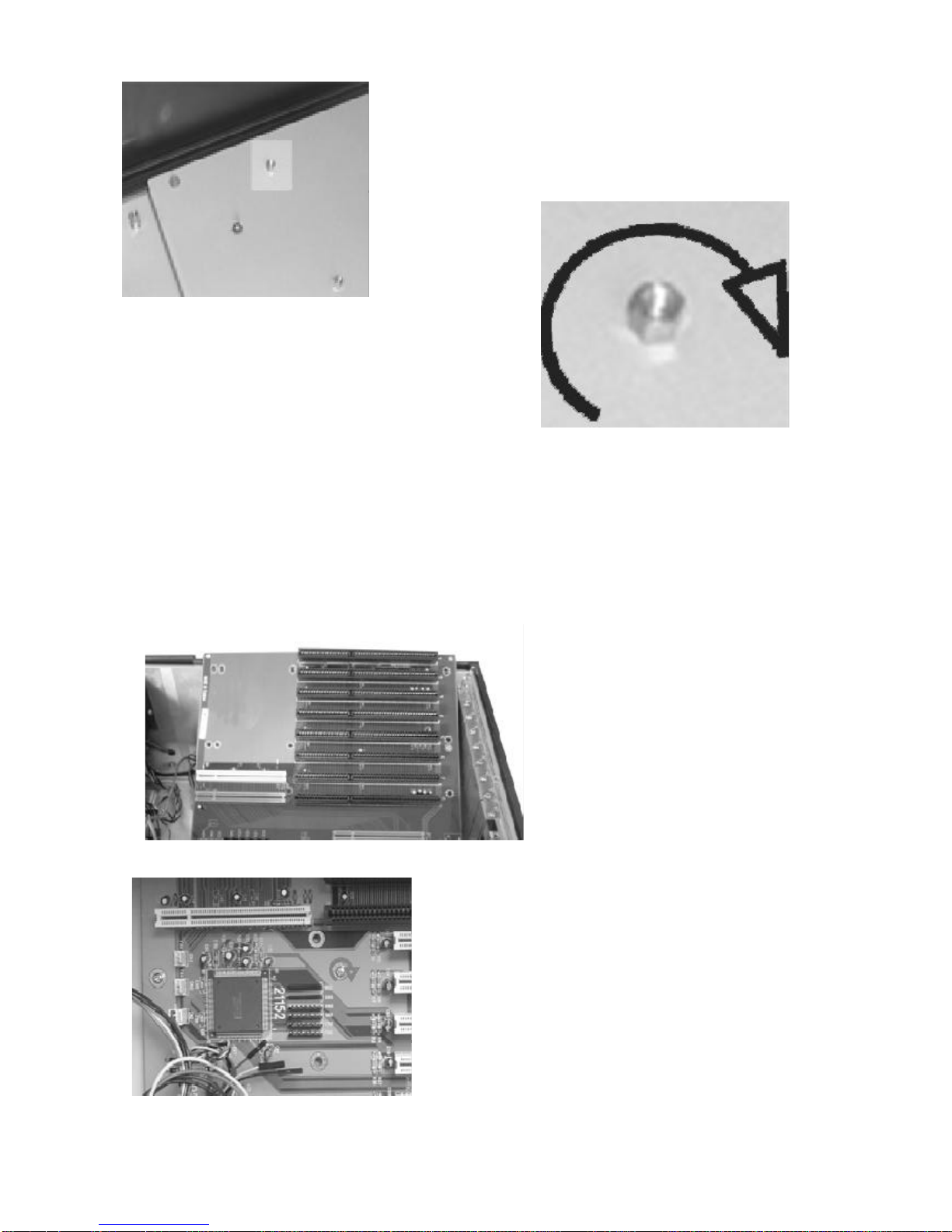
Removing theCardStabilizers
The stabilizerisdesigned tosecurelyholddownadd-on
cardsintheirexpansion slotswithplastichold-downclips.
The stabilizermustbe removed priortoadding boardsand
componentsinthe chassis.
Step 1.Removethe cardstabilizerreleasescrewsasshown.
Step 2.Removethe stabilizerand setthemaside.
Identifying theInternalParts
Afteryou remove thecardstabilizeryou
cancheck thecase contains,thefigureison
thenextpage.TheCDROMcableand audio
cablewill comewiththeslimCDROM
option.
Afteryou removed the driverscage fromthe chassis,setitaside.Yourarenowreadyeitherto
install the drivesinthe drivecage orinstall the backplane.
Removethe 2screwsand takeoutthe cage.
Removing theDrive cage

Installing TheBackplane
Makesurethatatno timeyou areworking on anyelectricalorelectroniccomponentswhileany
partofthe systemisenergized.Always disconnectthe power!Usecaution toprotectthe
delicateelectroniccomponents.Ground yourselfduring the installation ofthe motherboard
and othercomponents.
.Installing theStandoffs#9 Standoffs
#2 3x4screwstotighten backplane
#4 Washerbetween the backplane and screws
Takeamomenttostudythe inside ofthe chassis,making noteofthe location ofthe keyboard
Connectorifitcomewithbackplane.
Step 1.Slantthe backplane retention intothe chassisand position itinthe area itwill be
installed,making surethe alignmentofthe slotsand connectorsiscorrect.
Step 2.Makesurethe location ofthe backplane mounting points.You aregoing toinstall
standoffsatthosemounting points.
1 1
2
2
2
34
5 6 7 8910 11
13
12
1.speaker
2casefan
3fanboard
4LCDpower
cable
5audiocable
CDaudioin
6drivercage
7fancable
toSBC
8CDROM
signalcable
9powersupply
10resetcable
11audiocable
(SBC tospeaker)
12sidedoor
13mounthole
find the mountpointofthe backplane
insertthe stand offs
Thread clock-wisetoinsertthe standoff
reversetotakeoff the stand off
Yourpackage comeswithmetalstandoffsthreaded on one end and tapped on the opposite
end toreceiveamounting screw.
Step 3.Nowcarefullywithdrawthe backplane and thread the standoffsintothe mounting
holesinthe chassis.
Step 4.Align the mounting pointing pointsand insertthe screwsintothe metalstandoffs.
Step 5.Tighten the screws.(add washerifthe screwswill shortwiththe circuitofthe
backplane)
Slantthe backplane and lowerthe
backplane intothe chassis
Turnclockwisetosecurethe screws
you mayinsertthe insulating washerbetween
the screwand backplane toavoid
the shorting

Connecting thepowerConnector
The plug fromthe powersupplywill onlyinsertinone orientation.Pushdownfirmlymaking
surethe hookon the terminalblock clipsontothe plug.
Connecting the ChassisCables
The chassishas3internalcooling fan toreducethe temperatureofthe system,connecting the
fan powerconnectortofan adapterboard.
The flatpaneldisplayreceivesitspowerfrom
the powersupply.Find the wirebundlethat
endsina4-pinpowerconnectorfromthe chas-
sisside and plug itintoone ofthe powersupply
connectors.
Installing driverdisk tothedrive Cage
Step 1.Takeback the drivercage,takethe screw#5 and washer#3 fromyourpackage,and
securethe harddisk todrivercage
Step 2.Takethe floppydisk and Screw#2 fromyourpackage,and securethe floppydisk to
the drivecage.
Step 3.Connecttrhe cablestoharddisk and floppydisk.
Interiorspaceisgoing tobe tightened.Whileyou havethe driversoutside of
the chassis,plug inthe signalcables.
Ribbon cablesshouldalways be connected withthe colored stripe toPin1on the
connectors.
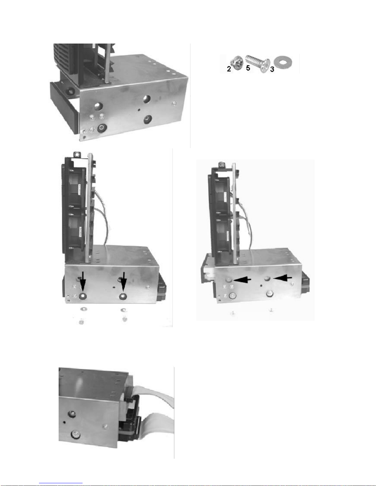
securethe harddisk todrivecage withscrew
#5,insertwasher#3 between cage and
screw,samewiththe otherside
securethe floppydisk todrivrcage with
screw#2,,samewiththe otherside
Connectthe signalcables
Ribbon cablesshouldalways be
connected withthe colored stripe to
Pin1on the connectors.
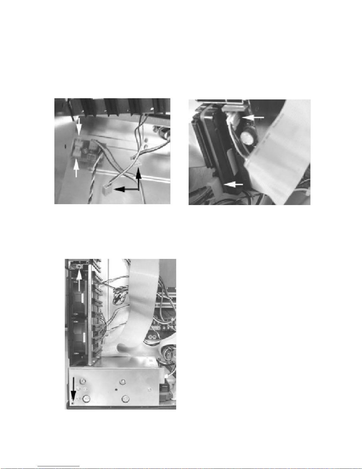
Installing theDriverCage
Step 1.Carefullyputthe drivecage back intothe chassis.
Step 2.Plugging the casefan powerconecttorintothe interfaceboardforfan power
Step 3.Plugging the powerconectorforfloppydisk and harddisk
Step 4.Align the mounting holesand insertthe screws#2
connectthe casefan powerconnect
(black arrow)tothe interfaceboard
(whitearrow)
CONNECTTHEDRIVEPOWERCONNECTOR
Align the mounting holesand insertthe
screws#2
Installing theSBC
Setting yourSBC Jumpers
Beforeinstalling the motherboardinthe chassis,install the CPUand setanydip-switchor
jumperon the SBC.Sincejumperand dip-switchsettingsareboard-specific,consultthe
manualthatcomeswiththe SBCand carefullyfollowthe directionstoconfigureyourSBC.
*
Makesurethatatno timeyou areworking on anyelectricalorelectroniccomponentswhileany
partofthe systemisenergized.Always disconnectthe power!Usecaution toprotectthe
delicateelectroniccomponents.Ground yourselfduring the installation ofthe motherboard
and othercomponents.
IInstalling the Standoffs
Step1.Locatethe sloton the backplane you wishtouse.Removethe slotcoverscrew
and then removethe slotcover.
Step 2.Setthe cardjumpersorswitchesaccording tothe manufacturer’s requirementsif
necessary.
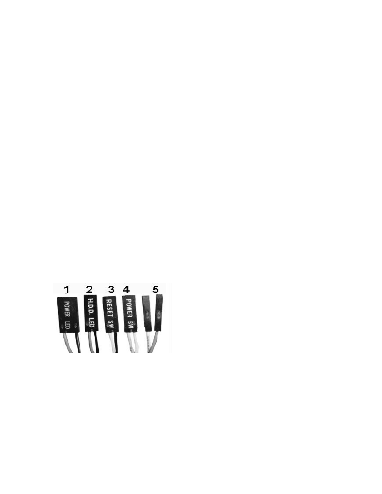
Step 3.Connectofthe small cablesfromthe chassis.The cablesarecolorcoded and labeled.
ConsultyourSBCmanualtoconnectthesecablestothe correctsetofterminalpins.
It maybe difficulttoknowforsurethatthe polarityofthe LEDconnectionsiscorrect. If an LED
failstolightwhen itshouldduring the testphase,you will be abletoshutdownand reverse
connectionsasneeded.
1.Power-on indicatorLED(orange and black).
2.Harddisk LED(blue and black)
3.Systemresetswitch(whiteand black).
4.Powerswitch(yellowand white).
5. InternalPCspeaker(blue and white).
Step 4.Connectthe drivesignalcabletoSBC
Connectthe CD ROM,floppydrive,harddisk drivesignalcabletothe SBCbeforethe SBCfix.
The ribbon cablesshouldalways be connected withthe colored stripe toPin#1 on the
connectors.
Step 5.Holdthe cardand align the edge connectorswiththe slot. Firmlypushthe cardintothe
slot.
Step 6.Usethe screwremoved earlier.Insertitintothe threaded holeand tighten it.
Connectthe signalcableand chassiscable
beforefixthe SBCFixthe SBCwithscrew#2
Installing theAdd-on Cards
The chassishas10 slotopeningssupporting up tonine (one isused bySBC)add-on cards.
Followthesestepstoinstall add-on cards
Add-on cardcan be extremelysensitivetoelectrostaticdischarge.Always handlethe cards
withcare.Holdthe cardbythe metalslotcoveroruppercorners.Becarefulnottotouch
the componentsorgoldedge connectors.
Step 1.Locatethe sloton the backplane you wishtouse.Removethe slotcoverscrewand
then removethe slotcover.
Step 2.Setthe cardjumpersorswitchesaccording tothe manufacturer’s requirementsif
necessary.
Step 3.Holdthe cardand align the edge connectorswiththe slot. Firmlypushthe cardintothe
slot.
Step 4.Usethe screwremoved earlier.Insertitintothe threaded holeand tighten it.
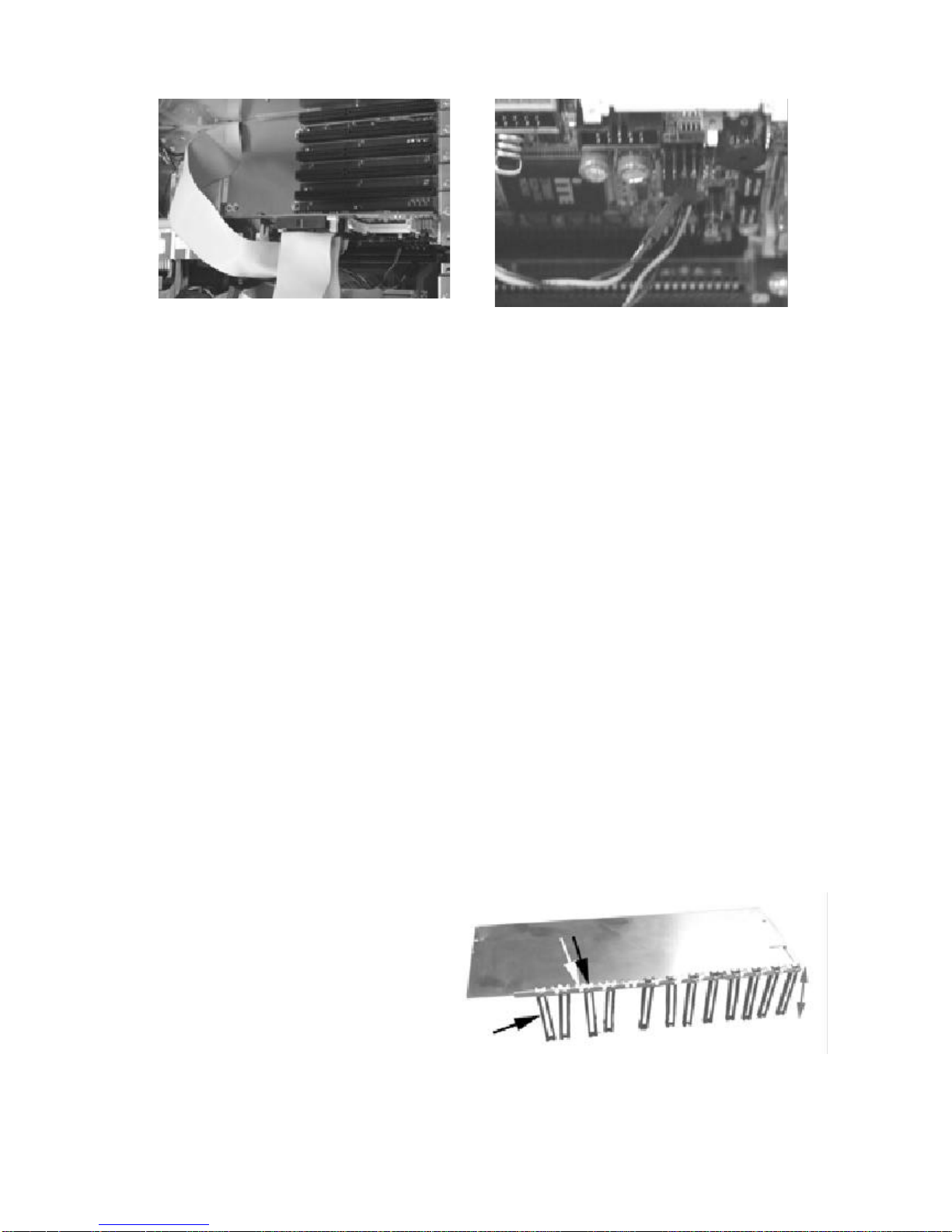
Installing theCardStabilizers
The proceduresofInstalling the CardStabilizers
The cardstabilizersaredesigned toholddownthe add-on cardssecurelyintheirslotsby
pressing the cardedgeswithplasticclips.Afteryou’veinstalled all the add-on cards,reinstall
the stabilizersusing the following steps.
Step 1.Loosen the screwsthatholdthe plasticclipsintheirbrackets.The clipsshouldbe able
toslide freelyinside the brackets.
Step 2.Align the stabilizerbarswiththeir
mounting holeson the chassis.Insertthe
mounting screwsand tighten them.You
mayhavetopull someofthe clipsup to
leaveenough spacebetween the clipand
the cardedge.Therearetwosetofholeforthe plasticclip,one for
ISA theo therforPCI, you can usethe righthole
according the slottype.

Step 3.Slide eachclipsotheycomeincontactwiththe top edge ofthe add-on cards.
Whileholding the clipfirmlyagainstthe cardedge,tighten the bracketscrews.
Step 4.Cutoff anyexcessivepartofthe plasticclip.
Step 5.Repeatthesestepsforthe otherstabilizer.
Slantthe add-on cardstabilizerand putit
inthe case,then setstraightand fixit.
Usescrew#7tosecureit. Usethe screwremoved earlier.Insertitinto
the threaded holeand tighten it.
Presstheplasticextenderfirmlyagainstthe
cardedgeandtightenscrew.Cutoff anyexcessivepartofthe plasticclip.
Preparing toStarttheSystem
Connecting theVideoand InputDevices
The location ofyourvideo output, keyboardand pointing deviceconnectorsareboard
dependent. Connectthe video cabletothe VGAoutputconnectoron yourSBCorothergraph-
ics card.Connectthe keyboardand pointing deviceconnectorstotheirsocketsand firmlypush
themintothe sockets.
Table of contents


