Advantech VEGA-1100 User manual
User Manual
VEGA-1100
HDMI 2.0 Over IP Multi-cast
Transceiver System with Bi-
directional IR, RS-232, Audio
Extender/Extractor, USB 2.0, &
Video Wall Support

VEGA-1100 User Manual ii
Copyright
The documentation and the software included with this product are copyrighted 2022
by Advantech Co., Ltd. All rights are reserved. Advantech Co., Ltd. reserves the right
to make improvements in the products described in this manual at any time without
notice. No part of this manual may be reproduced, copied, translated, or transmitted
in any form or by any means without the prior written permission of Advantech Co.,
Ltd. The information provided in this manual is intended to be accurate and reliable.
However, Advantech Co., Ltd. assumes no responsibility for its use, nor for any
infringements of the rights of third parties that may result from its use.
Acknowledgments
Intel® and Pentium® are trademarks of Intel® Corporation.
Microsoft Windows and MS-DOS are registered trademarks of Microsoft Corp.
All other product names or trademarks are properties of their respective owners.
Product Warranty (2 years)
Advantech warrants the original purchaser that each of its products will be free from
defects in materials and workmanship for two years from the date of purchase.
This warranty does not apply to any products that have been repaired or altered by
persons other than repair personnel authorized by Advantech, or products that have
been subject to misuse, abuse, accident, or improper installation. Advantech
assumes no liability under the terms of this warranty as a consequence of such
events.
Because of Advantech’s high quality-control standards and rigorous testing, most
customers never need to use our repair service. If an Advantech product is defective,
it will be repaired or replaced free of charge during the warranty period. For out-of-
warranty repairs, customers will be billed according to the cost of replacement mate-
rials, service time, and freight. Please consult your dealer for more details.
If you believe your product is defective, follow the steps outlined below.
1. Collect all the information about the problem encountered. (For example: CPU
speed, Advantech products used, other hardware and software used, etc.) Note
anything abnormal and list any onscreen messages displayed when the prob-
lem occurs.
2. Call your dealer and describe the problem. Please have your manual, product,
and any helpful information readily available.
3. If your product is diagnosed as defective, obtain a return merchandise authori-
zation (RMA) number from your dealer. This allows us to process your return
more quickly.
4. Carefully pack the defective product, a completed Repair and Replacement
Order Card, and a proof of purchase date (such as a photocopy of your sales
receipt) into a shippable container. Products returned without a proof of pur-
chase date are not eligible for warranty service.
5. Write the RMA number clearly on the outside of the package and ship the pack-
age prepaid to your dealer.
Part No. 2002A11000 Edition 1
Printed in Taiwan April 2022

iii VEGA-1100 User Manual
Declaration of Conformity
CE
This product has passed the CE test for environmental specifications when shielded
cables are used for external wiring. We recommend the use of shielded cables. This
type of cable is available from Advantech. Please contact your local supplier for
ordering information.
Test conditions for passing also include the equipment being operated within an
industrial enclosure. In order to protect the product from damage caused by electro-
static discharge (ESD) and EMI leakage, we strongly recommend the use of CE-
compliant industrial enclosure products.
FCC Class A
This equipment has been tested and found to comply with the limits for a Class A dig-
ital device, pursuant to part 15 of the FCC Rules. These limits are designed to pro-
vide reasonable protection against harmful interference when the equipment is
operated in a commercial environment. This equipment generates, uses, and can
radiate radio frequency energy and, if not installed and used in accordance with the
instruction manual, may cause harmful interference to radio communications. Opera-
tion of this equipment in a residential area is likely to cause harmful interference. In
this event, users are required to correct the interference at their own expense.
FCC Class B
This equipment has been tested and found to comply with the limits for a Class B dig-
ital device, pursuant to part 15 of the FCC Rules. These limits are designed to pro-
vide reasonable protection against harmful interference in a residential installation.
This equipment generates, uses, and can radiate radio frequency energy and, if not
installed and used in accordance with the instructions, may cause harmful interfer-
ence to radio communications. However, there is no guarantee that interference will
not occur in a particular installation. If this equipment does cause harmful interfer-
ence to radio or television reception, which can be determined by turning the equip-
ment off and on, the user is encouraged to try to correct the interference by one or
more of the following measures:
Reorient or relocate the receiving antenna.
Increase the separation between the equipment and receiver.
Connect the equipment into an outlet on a circuit different from that to which the
receiver is connected.
Consult the dealer or an experienced radio/TV technician for assistance.
FM
This equipment has passed the FM certification. According to the National Fire Pro-
tection Association, work sites are categorized into different classes, divisions, and
groups based on hazard considerations. This equipment is compliant with the specifi-
cations for Class I, Division 2, Groups A, B, C, and D indoor hazards.
VEGA-1100 User Manual iv
Technical Support and Assistance
1. Visit the Advantech website at http://support.advantech.comto obtain the latest
product information.
2. Contact your distributor, sales representative, or Advantech's customer service
center for technical support if you need additional assistance. Please have the
following information ready before calling:
–Product name and serial number
–Description of your peripheral attachments
–Description of your software (operating system, version, application software,
etc.)
–A complete description of the problem
–The exact wording of any error messages
Warnings, Cautions, and Notes
Document Feedback
To assist us with improving this manual, we welcome all comments and constructive
criticism. Please send all such feedback in writing to [email protected].
Packing List
Before system installation, check that the items listed below are included and in good
condition. If any item does not accord with the list, contact your dealer immediately.
1 x VEGA-1100
1 x IR blaster
1 x IR receiver
1 x DC 12V
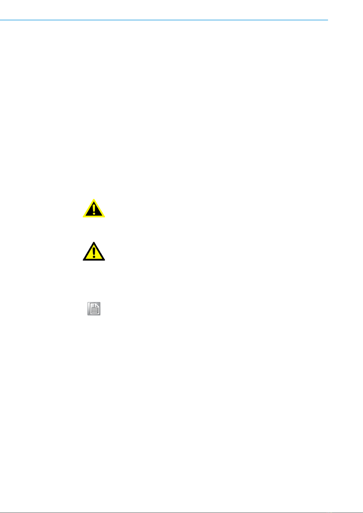
Warning! Warnings indicate conditions that if not observed can cause personal
injury!
Caution! Cautions are included to help prevent hardware damage and data
losses. For example,
“Batteries are at risk of exploding if incorrectly installed. Do not attempt
to recharge, force open, or heat the battery. Replace the battery only
with the same or equivalent type as recommended by the manufacturer.
Discard used batteries according to the manufacturer's instructions.”
Note! Notes provide additional optional information.

v VEGA-1100 User Manual
Safety Instructions
1. Read these safety instructions carefully.
2. Retain this user manual for future reference.
3. Disconnect the equipment from all power outlets before cleaning. Use only a
damp cloth for cleaning. Do not use liquid or spray detergents.
4. For pluggable equipment, the power outlet socket must be located near the
equipment and easily accessible.
5. Protect the equipment from humidity.
6. Place the equipment on a reliable surface during installation. Dropping or letting
the equipment fall may cause damage.
7. The openings on the enclosure are for air convection. Protect the equipment
from overheating. Do not cover the openings.
8. Ensure that the voltage of the power source is correct before connecting the
equipment to a power outlet.
9. Position the power cord away from high-traffic areas. Do not place anything over
the power cord.
10. All cautions and warnings on the equipment should be noted.
11. If the equipment is not used for a long time, disconnect it from the power source
to avoid damage from transient overvoltage.
12. Never pour liquid into an opening. This may cause fire or electrical shock.
13. Never open the equipment. For safety reasons, the equipment should be
opened only by qualified service personnel.
14. If any of the following occurs, have the equipment checked by service person-
nel:
The power cord or plug is damaged.
Liquid has penetrated the equipment.
The equipment has been exposed to moisture.
The equipment is malfunctioning, or does not operate according to the user
manual.
The equipment has been dropped and damaged.
The equipment shows obvious signs of breakage.
15. Do not leave the equipment in an environment with a storage temperature of
below -20 °C (-4 °F) or above 60 °C (140 °F) as this may damage the compo-
nents. The equipment should be kept in a controlled environment.
16. CAUTION: Batteries are at risk of exploding if incorrectly replaced. Replace only
with the same or equivalent type as recommended by the manufacturer. Discard
used batteries according to the manufacturer’s instructions.
17. In accordance with the IEC 704-1:1982 specifications, the sound pressure level
at the operator’s position does not exceed 70 dB (A).
DISCLAIMER: These instructions are provided according to IEC 704-1 standards.
Advantech disclaims all responsibility for the accuracy of any statements contained
herein.

VEGA-1100 User Manual vi
Safety Precautions - Static Electricity
Follow these simple precautions to protect yourself from harm and the products from
damage.
To avoid electrical shock, always disconnect the power from the PC chassis
before manual handling. Do not touch any components on the CPU card or
other cards while the PC is powered on.
Disconnect the power before making any configuration changes. A sudden rush
of power after connecting a jumper or installing a card may damage sensitive
electronic components.

vii VEGA-1100 User Manual
Contents
Chapter 1 Introduction..........................................1
1.1 Introduction ............................................................................................... 2
1.2 Features .................................................................................................... 2
1.3 Specifications ............................................................................................ 3
Chapter 2 Connection Diagram ...........................5
2.1 Connection Diagram ................................................................................. 6
2.2 Panel Description ...................................................................................... 7
Chapter 3 IR Pass-through...................................9
3.1 IR Pass-through ...................................................................................... 10
3.1.1 IR Extenders ............................................................................... 10
3.1.2 IR Sockets................................................................................... 10
3.1.3 IR Earphone Jack Definition ....................................................... 10
3.2 HDMI Pin Definition................................................................................. 11
Figure 3.1 Type A (Receptacle) HDMI....................................... 11
Chapter 4 Operation Approach..........................13
4.1 Software Control via Ethernet Port.......................................................... 14
4.1.1 System Requirements................................................................. 14
4.1.2 Start the Software Control Program............................................ 14
4.1.3 Control Interface ......................................................................... 14

VEGA-1100 User Manual viii

Chapter 1
1Introduction

VEGA-1100 User Manual 2
1.1 Introduction
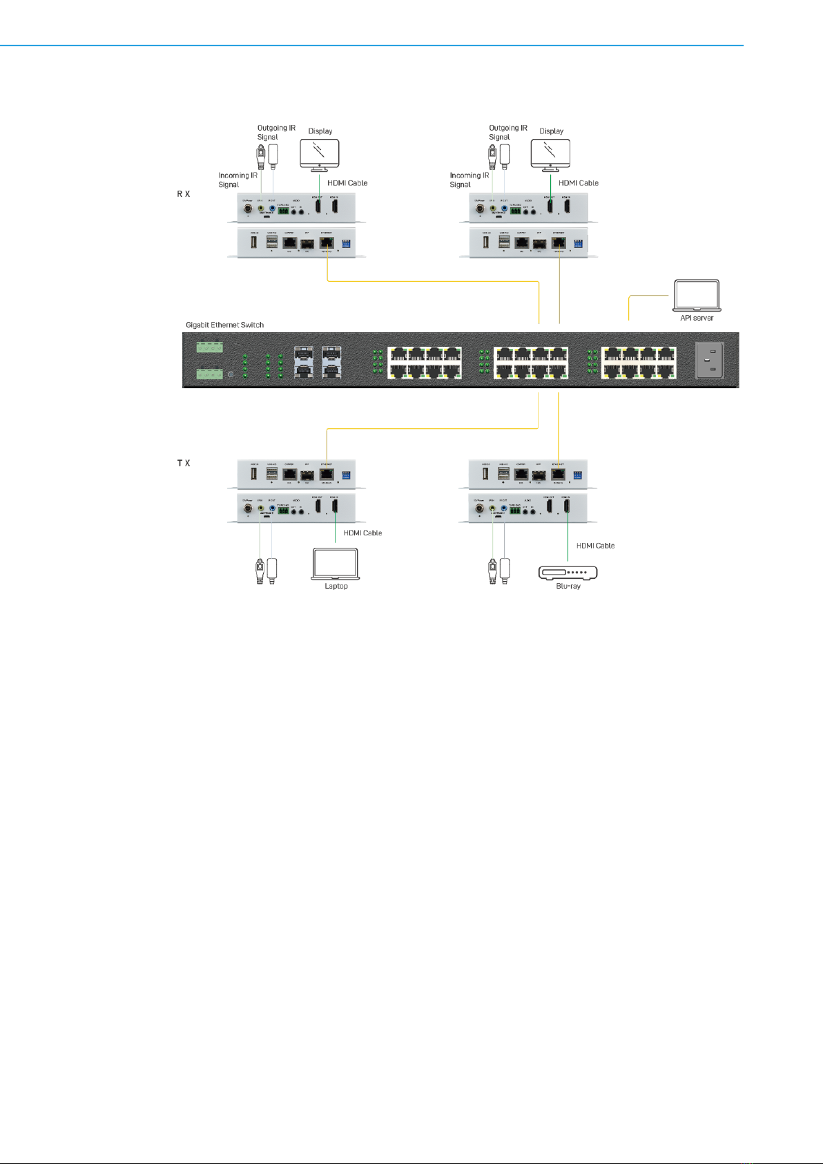
The Advantech VEGA-1100 HDMI 2.0 over IP multicast transceiver system — with
bi-directional IR, RS-232, audio extender/extractor, USB 2.0, and video wall support
— is designed to boost video/audio transmission distances. Illustratively, it increases
transmission distances to up to 100 m (330 ft) over copper and/or 300 m (990 ft)
(OM3)/400 m (1320 ft) (OM4) over fiber in ultra-HD 4K2K@60 (4:4:4) format. Using
VEGA-1100 enables users to extend ultra-HD signals from diverse HDMI sources to
distant displays/monitors. In addition, VEGA-1100 is HDCP compliant and supports
IR/RS-232 pass-through, audio extender/extractor, video wall, and multi-view capa-
bilities.
VEGA-1100 is a complete Ultra-HD 4K2K@60 (4:4:4) video broadcasting solution for
4K applications. It provides broadcasting management software and 10 Gigabit
Ethernet network switches (supported IGMP Snooping), VEGA-1100 supports
diverse broadcasting formats — including point-to-point, point-to-many, and multi-
casting formats. Multi-casting is based on managed 10 gigabit switch with 802.1Q
VLAN function which provides control remotely with multi device.
1.2 Features
Supports HDMI 2.0 & HDCP 2.2
Supports HDR and up to 4K@60 4:4:4
Extends the transmission over cat.6A cable up to 100 m (330 ft) from the HDMI
source at Ultra-HD 4K2K@60 4:4:4
Extends the transmission over multi-mode optic cable up to 300 m (990 ft)
(OM3)/400 m (1320 ft) (OM4)
Lite compress with less than 100us latency for 4K2K@60 4:4:4
HDCP & CEC Bypass
Supports EDID management
Can be configured as a full duplex transmitter and receiver when 4K@60 4:4:4
Slide switch to select transmission over 10G copper or SFP
Auto equalization
Pure unaltered uncompressed 7.1ch digital HDMI over cat.6A/fiber transmission
DTS-HD Master Audio and Dolby TrueHD high bit rate audio support
Supports bi-directional full frequency IR signal from 20KHz to 60KHz
Bi-directional analog audio path-through
Full duplex RS-232 control up to 115,200 bps
Integrated port for 1G LAN/ network device
Cat.6A/fiber extension and connection to a 10GbE Ethernet Switch (supported
IGMP snooping)
Supports software for configuring and upgrading devices. Software also controls
the switching operation for various signal types
Supports seamless switching
Supports Video Wall* & Multi-view function
Supports custom scaling to display
Supports USB 1.0
Supports the compensation of frame-tearing
*Up to 4K@60 4:4:4 (4K@60 4:4:4 needs light compression).
**Cat-6A cable or better is recommended for better performance.

3 VEGA-1100 User Manual
Chapter 1 Introduction
1.3 Specifications
Model Name VEGA-1100
Technical
Role of usage Transceiver
HDMI compliance HDMI 2.0a
HDCP compliance HDCP 2.2 & 1.4
Video bandwidth Single-link 594MHz [18Gbps]
Video support 480i/480p/720p/1080i/1080p60/4K2K@30/4K2K@60 4:4:4
HDMI over UTP 4K2K@60 4:4:4 100m (330ft) [CAT.6A]
HDMI over fiber 4K2K@60 4:4:4 up to 300m (990ft) (OM3)/400m (1320ft) (OM4)
[multi-mode optic cable]
Audio support Surround sound [up to 7.1ch) or stereo digital audio
Equalization Auto
Input TMDS signal 1.2 Volts [peak-to-peak]
Input DDC signal 5 Volts [peak-to-peak, TTL]
ESD protection Human body model — ±15kV [air-gap discharge] & ±8kV [contact
discharge]
PCB stack-up 6-layer board [impedance control — differential 100Ω; single 50Ω]
IR pass-thru Bi-directional
RS-232 support Yes
I/O connector 2 x HDMI + 4 x 3.5 mm + 3 x USB + 2 x RJ45 + 1 x fiber + 1 x RS-
232
HDMI source control Controllable via IR pass-through from RX to TX or TX to RX with IR
extenders
HDMI connector Type A [19-pin female]
RJ-45 connector WE/SS 8P8C
USB connector Type A
3.5mm connector IR receiver/IR blaster/Stereo
Mechanical
Housing Metal enclosure
Dimensions Model 172 x 162 x 30 mm (6.7 x 6.3 x 1.2 in)
[L x W x H] Package 325 x 196 x 92 mm (12.7 x 7.7 x 3.6 in)
Weight
Carton 490 x 426 x 352 mm (1.6 x 1.4 x1.2 in)
Model 685 g (1.5 lb)
Package 1.4 kg (3 lb)
Fixedness Wall-mounting case with screws
Power supply 12VDC
Power consumption 12.5 Watt [max]
Operation temperature 0 ~ 40 °C (32 ~ 104 °F)
Storage temperature -20 ~ 60 °C (-4 ~ 140 °F)
Relative humidity 20 ~ 90% RH [no condensation]

VEGA-1100 User Manual 4

Chapter 2
2Connection Diagram
VEGA-1100 User Manual 6
2.1 Connection Diagram

7 VEGA-1100 User Manual
Chapter 2 Connection Diagram
2.2 Panel Description
Front Panel
1. USB 1.0: Connect to keyboard or mouse
2. USB-HID:
[Top USB] Connect to keyboard or mouse
[Bottom USB]
1) Connect to keyboard or mouse when the USB routing on the software is set
as “remote”.
2) Connect to computer when the USB routing on the software is set as “local”.
3. Indicator LED: USB-HID LED.
4. 10G Copper IN/OUT: Plug in RJ-45 cable that needs to be linked to the other
unit.
5. Indicator LED: Link LED.
6. 10G SFP IN/OUT*: Plug in single/multi-mode fiber optic cables cable that needs
to be linked to the other unit (*fiber module is NOT included in the product).
7. Ethernet Port: Ethernet control port.
8. Dip Switch:
DIP Switch Position Description
PIN#1 PIN#2
ON [↓] OFF [↑] Reserved
ON [↓] ON [↓] Reserved
OFF [↑] ON [↓] Reserved
OFF [↑] OFF [↑] Reserved
PIN#3 ON [↓] Select transmission over SFP
OFF [↑] Select transmission over copper
VEGA-1100 User Manual 8
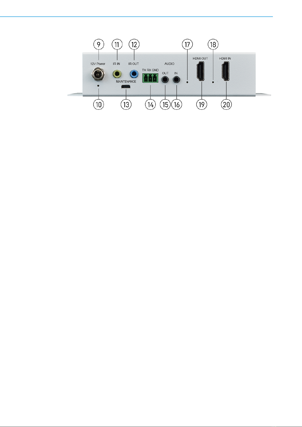
Rear Panel
9. +12VDC: Connect to a 12V power supply unit.
10. Indicator LED: Power LED.
11. IR Receiver: Infrared 3.5 mm socket for plugging in the extension cable of IR
receiver.
12. IR Blaster: Infrared 3.5 mm socket for plugging in the extension cable of IR
blaster.
13. Micro-USB: for F/W update.
14. RS-232 (terminal block format): The order of RS-232 pin are TX, RX, GND
(from the left side to the right).
15. Stereo OUT: Connect to analog stereo audio speaker.
16. Stereo IN: Connect to analog stereo audio source.
17. Indicator LED: HDMI out signal LED.
18. Indicator LED: HDMI in signal LED.
19. HDMI OUT: Connect to a HDMI display with a HDMI male-male cable.
20. HDMI IN: Connect to a HDMI source with a HDMI male-male cable.

Chapter 3
3IR Pass-through

VEGA-1100 User Manual 10
3.1 IR Pass-through
3.1.1 IR Extenders
IR Blaster IR Receiver
3.1.2 IR Sockets
IR BLASTER: plug in the IR blaster to emit all IR command signals received from the
IR receiver from the other end to control the devices corresponding to the IR signals.
IR RECEIVER: plug in the IR receiver to receive all IR command signals from the IR
remote controls of the corresponding devices.
3.1.3 IR Earphone Jack Definition
IR Blaster IR Receiver
Caution! Incorrect placement of IR Blaster and Receiver may result in the failure
of the IR extenders. Please check carefully before plugging in the IR
extender to the respective IR sockets. Warranty will not cover the dam-
age.
If necessary, users can buy replacement IR extension cables that are compatible
with the definition of the IR sockets for the extender. However, IR cables longer
than 2 m (6 ft) may not work.

11 VEGA-1100 User Manual
Chapter 3 IR Pass-through
3.2 HDMI Pin Definition
Figure 3.1 Type A (Receptacle) HDMI
Pin 1 TMDS Data2+ Pin 11 TMDS Clock Shield
Pin 2 TMDS Data2 Shield Pin 12 TMDS Clock–
Pin 3 TMDS Data2– Pin 13 CEC
Pin 4 TMDS Data1+ Pin 14 Reserved (N.C. on device)
Pin 5 TMDS Data1 Shield Pin 15 SCL
Pin 6 TMDS Data1– Pin 16 SDA
Pin 7 TMDS Data0+ Pin 17 DDC/CEC Ground
Pin 8 TMDS Data0 Shield Pin 18 +5V Power
Pin 9 TMDS Data0– Pin 19 Hot Plug Detect
Pin 10 TMDS Clock+

VEGA-1100 User Manual 12
Table of contents
Other Advantech Transceiver manuals

Popular Transceiver manuals by other brands


Vertex Standard
Vertex Standard VX-160V Service manual

Beifeng Telecom
Beifeng Telecom BF-3000 user manual

Standard Communications
Standard Communications TX3200 instruction manual

Technisonic Industries Limited
Technisonic Industries Limited TFM-566 Installation and operating instructions

ADTRAN
ADTRAN 11.3G XFP manual

Elinchrom
Elinchrom EL-Skyport Transceiver RX Instructions for use


