Yaesu VX-5R User manual

50/144/430MHZTRIPLE-BAND
HEAVY DUTY FM TRANSCEIVER
VX-5R
OPERATING MANUAL
YAESU MUSEN CO., LTD.
1-20-2 Shimomaruko, Ota-Ku, Tokyo 146-8649, Japan
YAESU U.S.A.
17210 Edwards Rd., Cerritos, CA 90703, U.S.A.
YAESU EUROPE B.V.
Snipweg 3, 1118DN Schiphol, The Netherlands
YAESU UK LTD.
Unit 12, Sun Valley Business Park, Winnall Trading Estate
Winchester, Hampshire, SO23 0LB, U.K.
YAESU GERMANY GmbH
Am Kronberger Hang 2, D-65824 Schwalbach, Germany
YAESU HK LTD.
11th Floor Tsim Sha Tsui Centre, 66 Mody Rd.,
Tsim Sha Tsui East, Kowloon, Hong Kong
Downloaded by
RadioAmateur.EU

Contents
Introduction .......................................... 1
Controls & Connections ....................... 2
Display Icons & Indicators .................. 3
Keypad Function .................................. 4
Accessories & Options.......................... 6
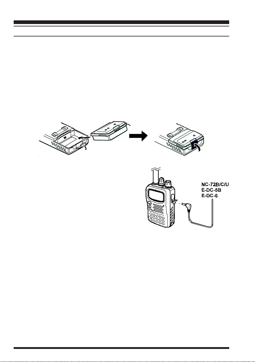
Installation of Accessories.................... 7
Antenna Installation ............................................. 7
Belt Clip Installation ............................................ 7
Installation of FNB-58LI Battery Pack ................. 8
Installation of FBA-23 Alkaline Battery Case ...... 9
Battery Life Information ..................................... 10
AC Operation Using NC-72 ............................... 10
Interface of Packet TNCs................... 11
Operation............................................. 12
Switching Power On and Off ............................. 12
Adjusting the Volume Level .............................. 12
Squelch Adjustment ........................................... 12
Selecting the Operating Band ............................. 13
Frequency Navigation ........................................ 14
Transmission ...................................................... 15
AM Broadcast Reception ................................... 15
AM Aircraft Reception ...................................... 16
FM Broadcast/TV Audio Reception.........
16
Weather Broadcast Reception ............................ 17
Keypad/LCD Illumination .................................. 18
Advanced Operation .......................... 20
Setting the Frequency Display Image Size.......... 20
VFO Split Mode ................................................. 21
VFO Linking ...................................................... 22
Changing the Channel Steps .............................. 22
Changing the Operating Mode ........................... 23
Repeater Operation ............................................ 24
CTCSS Operation .............................................. 26
DCS Operation................................................... 27
Tone Search Scanning........................................ 28
CTCSS/DCS Bell Operation .............................. 29
Tone Calling (1750 Hz) ..................................... 29
Changing the Transmitter Power Level .............. 30
Changing the TX Deviation Level...................... 30
Transmitter Time-Out Timer(TOT) ................... 31
Busy Channel Lock-Out (BCLO) ....................... 31
Receive Battery Saver Setup .............................. 32
TX Battery Saver ............................................... 32
Disabling the BUSY/TX LED ............................ 33
Battery Utilization Monitor ................................ 33
Automatic Power-Off(APO) Feature ................. 33
Automatic Power-On Feature ............................. 34
Keyboard Locking.............................................. 34
Disabling the Keypad Beeper ............................. 35
Checking the Battery Voltage ............................ 35
Temperature Display .......................................... 35
DTMF Operation ............................................... 36
Emergency Channel Operation .......................... 37
ARTS (
Automatic Range Transponder System
)......... 38
Memory Mode..................................... 42
Memory Storage................................................. 42
Storing Independent Transmit Frequencies ........ 42
Memory Recall................................................... 43
HOME Channel Memory ................................... 43
Labeling Memories ............................................ 44
Memory Offset Tuning....................................... 44
Masking Memories ............................................ 45
Memory Group Operation .................................. 45
Scanning .............................................. 46
VFO Scanning ................................................... 47
Memory Scanning .............................................. 47
How to Skip a Channel During Memory Scan.... 48
Preferential Memory Scan .................................. 48
Programmable Memory Scan (PMS) .................. 49
“Priority Channel” Scanning (Dual Watch) ....... 50
Automatic Lamp Illumination on Scan Stop ....... 50
Band Edge Beeper ............................................. 51
Smart Search Operation .................... 52
Spectrum Analyzer Operation .......... 53
Barometric Pressure/
Altitude Metering .......... 54
Display Customization ....................... 56
Icon Mode .......................................................... 56
Meter Symbols ................................................... 56
Power-Off Display Mode ................................... 57
Display Contrast................................................. 57
Reset..................................................... 58
Cloning................................................. 59
Set Mode .............................................. 60
Specifications....................................... 70
Installation of the SU-1 ...................... 72

VX-5R OPERATING MANUAL 1
Introduction
The VX-5R is a miniature triband FM transceiver with extensive receive frequency cover-
age, providing leading-edge features for VHF and UHF two-way amateur communications
along with unmatched monitoring capability.
The VX-5R’s small size allows you to take it anywhere - hiking, skiing, or while walking
around town, and its operating flexibility brings the user many avenues of operating enjoy-
ment. Besides 50, 144, and 430 MHz transceive operation, the VX-5R provides receive
coverage of the AM (MF) and FM broadcast bands, HF Shortwave Bands up to 16 MHz,
VHF and UHF TV bands, the VHF AM aircraft band, and a wide range of commercial and
public safety frequencies! And the optional Barometer pressure Sensor Unit provides readout
of barometric pressure and altitude while mountain climbing or hiking.
The transmitter section provides 5 Watts of clean power output on the 50 MHz and 144
MHz bands with the suppliedFNB-58LI Battery Pack, and 4.5 Watts output on 430 MHz.
When 13.8V DC power is supplied from an external source, power output is five watts on
all bands. A wide variety of tone signaling formats are built into the VX-5R, in addition to
Yaesu’s exclusive ARTS™ (Auto-Range Transponder System), which “beeps” the user
when you move out of communications range with another ARTS™-equipped station.
We appreciate your purchase of the VX-5R, and encourage you to read this manual thor-
oughly, so as to learn about the many exciting features of your exciting new Yaesu hand-
held transceiver!

VX-5R OPERATING MANUAL2
Controls & Connections
MIC
The internal micro-
phone is located at
the bottom right-hand
corner of the display.
SPEAKER
The internal speaker
is located directly be-
low the display.
MONI
Pressing this key dis-
ables the noise
squelching action, al-
lowing you to hear
very weak signals
near the background
noise level.
PTT
Press this key to
transmit, and release
it to receive after your
transmission is com-
pleted.
MIC/SP
This four-conductor
miniature jack pro-
vides connection
points for microphone
audio, earphone au-
dio, PTT, and ground.
EXT DC
This coaxial DC jack
allows connection to
an external DC power
source (10-16V DC).
The center pin of this
jack is the Positive
(++
++
+) line.
DIAL
The main tuning
Dial is used for
setting the operat-
ing frequency, and
also is used for
Menu selections
and other adjust-
ments.
ANTENNA
Connect the sup-
plied rebber flex
antenna (or an-
other antenna pre-
senting a 50Ωim-
pedance) here.
VOLUME
This control ad-
justs the audio vol-
ume level. Clock-
wise rotation in-
creases the vol-
ume level.
TX/BUSY
This indicator
glows Red during
transmission, and
Green when a sig-
nal is being re-
ceived (of suffi-
cient strength to
open the noise
squelch).
PWR
Press and hold this
switch for one second
to toggle the trans-
ceiver’s power on and
off.
KEYPAD
These 17 keys select many
of the most important oper-
ating features on theVX-5R.
The function of the keys are
described in detail on pages
4 and 5.

VX-5R OPERATING MANUAL 3
Display Icons & Indicators

VX-5R OPERATING MANUAL4
Keypad Functions
Frequency Entry
Digit “1”
[1(TN)FRQ][BAND(SET)AR][
2(CD)TAG]
Change the Frequency
Band
Enter the “Set” (Menu)
mode.
Activate the ARTSTM
Feature.
Frequency Entry
Digit “2”
Activate CTCSS or
DCS Operation.
Enables display of the
Sub-band Frequency.
Select the CTCSS tone
frequency or DCS
code number.
Select the display type
(Frequency or
Frequency+Alpha-
numeric Tag) during
Memory operation.
[4(MG)DSP][
5(AP)ICO]
Press Key
Press [F/W]+
Press and hold
Key
[HM/RV(EMG)]
[7(ST)TMP][
8(BRO)][TX PO(LOCK)]
Frequency Entry
Digit “4”Frequency Entry
Digit “5”
Frequency Entry
Digit “7”Frequency Entry
Digit “8”
Switch to the “Home”
(favorite frequency)
Channel.
Activate the EMERGENCY
Feature.
Reverse the transmit
and receive frequen-
cies while working
through a repeater.
Activate the Automatic
Power-Off Feature.
Select the desired
transmitter power
output level.
Activate the Key
Lockout Feature.
Select the synthesizer
steps to be used
during VFO operation.
Display the current
temperature inside the
transceiver’s case.
Display the current
Barometric Pressure.
None
Activate the Memory
Group mode.
Switches display
between
Large
Character
and
Small
Character mode
.
Switch the display
lavels between the
“
Alpha-numeric
”
and
“
Icon
” formats.
Press Key
Press Key
Press [F/W]+
Press [F/W]+
Press and hold
Key
Press and hold
Key
None

VX-5R OPERATING MANUAL 5
Keypad Functions
Switch to the Memory
mode.
Frequency Entry
Digit “3”
Display the Battery
Type and Battery
Voltage.
Activate the DTMF
Autodialer Function.
Designate a Memory
Channel to be
“skipped” during
scanning.
Initiate Memory
Channel scanning.
Frequency Entry
Digit “6”
Frequency Entry
Digit “9”
Frequency Entry
Digit “0”
Select the direction of
the uplink frequency
shift (either “–,” “+” or
simplex) during
repeater operation.
Display the operating
time and total transmit
time since you most
recently turned the
transceiver on.
Adjust the Squelch
threshold level.
Recall the “Weather”
broadcast channel.
Turn the keypad’s
Beeper on or off.
Display the current
Altitude.
Select the VFO mode.
Activate the Dual
Watch feature.
Activate VFO
scanning.
[MR(SKP)SC][3(DT)VLT]
[0(SQ)WX][6(RP)ONT]
[VFO(DW)SC][9(BP)ALT]
[PTT]
[MON]
[LAMP]
Transmit.
Temporary High Power
Transmit.
Transmit.
Illuminate the LCD and
keypad for 5 seconds.
Illuminate the LCD and
keypad until you press
the key again.
Activate the Spectrum
Analyzer feature.
USA version:
Disable the Noise and
Tone Squelch.
European version:
Activate the T. CALL.
Reverse the transmit
and receive frequen-
cies while working
through a repeater.
None
Press Key
Press Key
Press [F/W]+
Press [F/W]+
Press [F/W]+
Press Key
Press and hold
Key
Press and hold
Key
Press and hold
Key

VX-5R OPERATING MANUAL6
ACCESSORIES SUPPLIED WITH THE VX-5R
FNB-58LI Battery Pack (7.2V/1100mAh)
NC-72B/C/U Battery Chareger
Belt Clip
Hand Strap
Antenna
Operating Manual
Warranty Card
AVAILABLE OPTIONS FOR YOUR VX-5R
Accessories & Options
CSC-73 Soft Case
CD-15 Rapid Charger (requires NC-72B/C/U)
FBA-23 2 x “AA” Cell Battery Case (batteries not supplied)
FNB-58LI Battery Pack
E-DC-5B DC Cable w/Noise Filter
NC-72B/C/U Battery Chareger
E-DC-6 DC Cable; plug and wire only
CT-44 Microphone Adapter
MH-37A4B Earpiece/Microphone
MH-34B4B Speaker/Microphone
VC-25 VOX Headset
CN-3 BNC-to-SMA Adapter
SU-1 Barometric Pressure Sensor Unit
CT-27 Cloning Cable
Availability of accessories may vary. Some accessories are supplied as standard per local
requirements, while others may be unavailable in some regions. Consult your Yaesu Dealer for
details regarding these and any newly-available options. Connection of any non-Yaesu-ap-
proved accessory, should it cause damage, may void the Limited Warranty on this apparatus.

VX-5R OPERATING MANUAL 7
ANTENNA INSTALLATION
The supplied antenna provides good results over the entire frequency range of the trans-
ceiver. However, for enhanced base station medium-wave and shortwave reception, you
may wish to connect an external (outside) antenna.
The supplied antenna consists of two sections: the “Base Antenna” (used for operation
above 50 MHz), and the “Extender Element” (used for monitoring of frequencies below 50
MHz).
To install the supplied antenna
Hold the bottom end of the antenna, then screw it onto the mat-
ing connector on the transceiver until it is snug. Do not over-
tighten by use of extreme force.
When operating the VX-5R on frequencies lower than the 50
MHz band, disconnect the antenna cap from the base antenna
then screw the Extender Element onto the Base Antenna.
Notes:
¦Never transmit without having an antenna connected.
¦When installing the supplied antenna, never hold the upper
part of the antenna while screwing it onto the mating con-
nector on the transceiver.
¦If using an external antenna for transmission, ensure that
the SWR presented to the transceiver is 1.5:1 or lower.
¦Take care not lose the antenna cap when removing it from
the Base Antenna.
BELT CLIP INSTALLATION
To install the Belt Clip, first place the loop of the Hand Strap into the groove at the top of
the Belt Clip, and run the loop of the strap around the round mounting ridge for the Belt
Clip. Now insert the mounting screw through the belt clip, and affix it snugly to the mount-
ing hole on the back of the transceiver, being careful not to allow the Hand Strap to become
mis-aligned.
Installation of Accessories

VX-5R OPERATING MANUAL8
Installation of Accessories
INSTALLATION OF FNB-58LI BATTERY PACK
The FNB-58LI is a high-performance Lithium-Ion battery providing high capacity in a
very compact package. Under normal use, the FNB-58LI may be used for approximately
300 charge cycles, after which operating time may be expected to decrease. If you have an
old battery pack which is displaying capacity which has become diminished, you should
replace the pack with a new one.
rPush the bottom latch slightly to the “OPEN” position.
rInstall the FNB-58LI as shown in the illustration.
rRe-lock the bottom plate by carefully pressing the hinged latch cover back into its
normal operating position.
If the battery has never been used, or its charge is
depleted, it may be charged by connecting the NC-
72B/C/U Battery Charger, as shown in the illustra-
tion, to the EXT DC jack. If only 12 ~ 16 Volt DC
power is available, the optional E-DC-5B or E-DC-
6DC Adapter (with its cigarette lighter plug) may
also be used for charging the battery, as shown in the
illustration.
The display will indicate “now chargingnow charging
now chargingnow charging
now charging” while the battery is being charged. When
charging is finished, the display will change to indicate “completecomplete
completecomplete
complete.”

VX-5R OPERATING MANUAL 9
Installation of Accessories
INSTALLATION OF FBA-23 (OPTION)ALKALINE BATTERY CASE
The optional FBA-23 Battery Case allows receive monitoring using two “AA” size Alka-
line batteries. Alkaline batteries can also be used for transmission in an emergency, but
power output will only be 300 mW, and battery life will be shortened dramatically.
To Install Alkaline Batteries into the FBA-23
rSlide the batteries into theFBA-23 as shown in the illustration,
with the Negative [] side of the batteries touching thespring
connections inside the FBA-23.
rUnlock the bottom plate by pushing the latch in the “OPEN”
direction.
rInstall the FBA-23 as shown in the illustration, with the [+]
side facing the bottom of the transceiver.
rRe-lock the bottom plate by carefully pressing the latch cover
back into its normal operating position.
TheFBA-23 does not provide connections for charging, since Alkaline cells cannot be re-
charged. Therefore, the NC-72B/C/U, E-DC-5B, or E-DC-6 may safely be connected to
the EXT DC jack when the FBA-23 is installed.
Notes:
¦The FBA-23is designed for use only with AA-type Alkaline cells.
¦If you do not use the VX-5R for a long time, remove the Alkaline batteries from the
FBA-23, as battery leakage could cause damage to the FBA-23 and/or the trans-
ceiver.

VX-5R OPERATING MANUAL10
BATTERY LIFE INFORMATION
When the battery charge is almost depleted, a “Low Voltage” indicator will appear on the
display. When this icon appears, it is recommended that you charge the battery soon.
Installation of Accessories
Operating Band Battery Life (Approx.) Low Voltage Indicator
FNB-58LI FBA-23
50MHz(1) 6.5 hours 7.5 hours
144 MHz(1) 6 hours 7 hours
430 MHz(1) 5.5 hours 6 hours
Other Bands (2) 15 hours 9 hours
: Battery is nearing depletion.
Prepare to replace the battery.
Prepare to charge the battery.
: Battery voltage is
critically low
.
Prepare to replace the battery.
Prepare to charge the battery.
(1) TX 6 sec., RX 6 sec. and Squelched 48 sec.
(2) Continuous signal reception
The current battery voltage can be displayed manually on the LCD, by following the in-
structions on page 35.
Battery capacity may be reduced during extremely cold weather operation. Keeping the
radio inside your parka may help preserve the full charge capacity.
AC OPERATION USING NC-72B/C/U (RECEIVING ONLY)
TheVX-5R may be operated from your house current by use of the supplied NC-72B/C/U
Battery Charger.
To use the NC-72B/C/U, turn the transceiver off, then plug the miniature connector of the
Battery Charger into the EXT DC jack on the side of the radio. Now plug the Battery
Charger into the wall outlet. You may now turn on the transceiver.
Important Notice
When using an external DC power source supplied via theE-DC-5B or E-DC-6, if
power is momentarily interrupted a safety feature will be activated inside the VX-
5R, so as to minimize the possibility of damage to the microprocessor. Such a
power interruption might occur when a vehicle's ignition is turned on or off, or if the
DC power cable is unplugged, or if the DC power supply is turned off.
In the event of such a momentary power interruption, theVX-5R will return to the
original VFO or Memory Channelto which the
VX-5R
was tuned when it was first
turned on during this operating session. For example, if you started operation on
Memory Channel 2, at 145.400 MHz, but DC power input is interrupted later while
you are on Memory Channel 25, The VX-5R will revert to Memory Channel 2
(145.400 MHz) when the power situation stabilizes.
This is a (normal) protection feature, and you may quickly return to Menory Chan-
nel 25 by pressing .

VX-5R OPERATING MANUAL 11
The VX-5R may be used for Packet operation, using the optional CT-44 microphone
adapter (available from your Yaesu dealer) for easy interconnection to commonly-avail-
able connectors wired to your TNC. You may also build your own cable using a four-
conductor miniature phone plug, per the diagram below.
The audio level from the receiver to the TNC may be adjusted by using the VOLUME
knob, as with voice operation. The input level to the VX-5R from the TNC should be
adjusted at the TNC side; the optimum input voltage is approximately 5 mV at 2 kΩ.
Be sure to turn the transceiver and TNC off before connecting the cables, so as to prevent
voltage spikes from possibly damaging your transceiver.
Interface of Packet TNCs
Downloaded by
RadioAmateur.EU

VX-5R OPERATING MANUAL12
Hi! I’m R. F. Radio, and I’ll be helping you along as you learn the many
features of the
VX-5R
. I know you’re anxious to get on the air, but I encour-
age you to read the “Operation” section of this manual as thoroughly as
possible, so you’ll get the most out of this fantastic new transceiver. Now. . .let’s get
operating!
SWITCHING POWER ONAND OFF
•Be sure the battery pack is installed, and that the battery is fully charged. Connect the
antenna to the top panel ANTENNA jack.
‚Press and hold in the orange PWRswitch (on the left side of the front panel) for one
second. Two beeps will be heard when the switch has been held long enough, and the
frequency display will soon appear. After another two seconds, the receive-mode Bat-
tery Saver function will become active, unless you have disabled it (see page 32).
ƒTo turn the VX-5R off, press and hold in the PWR switch again for one second.
If you don’t hear the two “Beep” tones when the radio comes on, the Beeper
may have been disabled via the Menu system. See page 35, which tells you
how to reactivate the Beeper.
ADJUSTING THE VOLUME LEVEL
Rotate the VOLUME control (immediately to the right of the Antenna) to set the desired
audio level. Clockwise rotation increases the volume level.
SQUELCH ADJUSTMENT
The VX-5R’s Squelch system allows you to mute the background noise when no signal is
being received. Not only does the Squelch system make “standby” operation more pleas-
ant, it also significantly reduces battery current consumption.
The Squelch system may be adjusted independently for the FM and Wide-FM (FM Broad-
cast) modes.
•Press the [F/W]key momentarily, then immediately press [0(SQ)WX]. This provides
a “short-cut” to Menu Item #01 (SQUELCHSQUELCH
SQUELCHSQUELCH
SQUELCH).
‚Now rotate the DIAL knob clockwise; you will notice that the noise will disappear
after a few “clicks” of the DIAL. When you find the point where the background noise
is just silenced, (typically at a setting of about “3” or “4” on the scale), leave the DIAL
at that setting; this is point of maximum sensitivity to weak signals.
ƒWhen you are satisfied with the Squelch threshold setting, press thePTT key momen-
tarily to save the new setting and exit to normal operation.
„You may also adjust the Squelch setting by using the “Set” (Menu) mode. See page 61
for details.
Operation

VX-5R OPERATING MANUAL 13
If you’re operating in an area of high RF pollution, you may need to con-
sider “Tone Squelch” operation using the built-in CTCSS Decoder. This fea-
ture will keep your radio quiet until a call is received from a station sending
a carrier which contains a matching (subaudible) CTCSS tone. Or if your friends have
radios equipped with DCS (Digital Coded Squelch) like your VX-5R has, try using that
mode for silent monitoring of busy channels.
SELECTING THE OPERATING BAND
The VX-5Rcovers an incredibly wide frequency range, over which a number of different
operating modes are used. Therefore, the VX-5R’s frequency coverage has been divided
into different operating bands, each of which has its own pre-set channel steps and operat-
ing modes. You can change the channel steps and operating modes later, if you like (see
pages 22 and 23).
To Change Operating Bands
•Press the[BAND(SET)AR]key repetitively.
You will see the LCD indication change as
you press the [BAND(SET)AR]key.
‚The VX-5R uses a dual VFO system (ex-
plained in detail on page 20). To switch from
the “Main” VFO (VFO-A) to the “Sub”
(VFO-B) VFO instantly, press the
[VFO(DW)SC]key momentarily. Pressing
the [VFO(DW)SC]key once more will re-
turn the VX-5R to VFO-A.
ƒOnce you have selected the desired band, you
may initiate manual tuning (or scanning) per
the discussions below.
Operation
BAND Frequency Range
BC Band 0.5 ~ 1.8 MHz
SW Band 1.8 ~ 16 MHz
FM BC 59 ~ 108 MHz
TV Band 174 ~ 222 & 470 ~ 729 MHz
50 MHz Ham 48 ~ 59 MHz
144 MHz Ham 137 ~ 174 MHz
430 MHz Ham 420 ~ 470 MHz
AIR Band 108 ~ 137 MHz
Action Band 1 222 ~ 420 MHz
Action Band 2 800 ~ 999 MHz

VX-5R OPERATING MANUAL14
FREQUENCY NAVIGATION
The VX-5R will initially be operating in the “VFO” mode, as just described. This is a
channelized system which allows free tuning throughout the currently-selected operating
band. You can confirm that you are in the VFO mode by looking in the upper-left-hand
corner of the display; if you see “Va” (which stands for “VFO-A”) and/or “Vb” (VFO-B)
along the left edge of the LCD, then you are in the VFO mode.
Three basic frequency navigation methods are available on the VX-5R:
1. Tuning Dial
Rotation of the DIAL allows tuning in the pre-programmed steps established for the cur-
rent operating band. Clockwise rotation of the DIAL causes theVX-5R to be tuned toward
a higher frequency, while counter-clockwise rotation will lower the operating frequency.
If you press the [F/W]key momentarily, then rotate the DIAL, frequency steps of 1 MHz
will be selected. This feature is extremely useful for making rapid frequency excursions
over the wide tuning range of the VX-5R.
2. Direct Keypad Frequency Entry
The desired operating frequency may be entered directly from the keypad.
The operating mode will automatically be set once the new frequency is entered via the
keypad.
To enter a frequency from the keypad, just press the numbered digits on the keypad in the
proper sequence. There is no “decimal point” key on the VX-5R, so if the frequency is
below 100 MHz (e.g. 15.150 MHz), any required leading zeroes must be entered.
Examples:
To enter 146.520 MHz, press
To enter 15.255 MHz, press
To enter 1.250 MHz (1250 kHz), press
To enter 0.950 MHz (950 kHz), press
3. Scanning
From the VFO mode, press and hold in the [VFO(DW)SC]key for one second.
The VX-5R will begin scanning toward a higher frequency, and will stop when it receives
a signal strong enough to break through the Squelch threshold. The VX-5R will then hold
on that frequency according to the setting of the “RESUME” mode (Menu #12). See page
63 for details.
If you wish to reverse the direction of the scan (i.e. toward a lower frequency, instead of a
higher frequency), just rotate the DIAL one click in the counter-clockwise direction while
the VX-5R is scanning. The scanning direction will be reversed. To revert to scanning
toward a higher frequency once more, rotate the DIAL one click clockwise.
Operation

VX-5R OPERATING MANUAL 15
TRANSMISSION
Once you have set up an appropriate frequency inside one of the three Amateur bands on
which theVX-5R can transmit (50 MHz, 144 MHz or 430 MHz), you’re ready to transmit.
These are the most basic steps; more advanced aspects of transmitter operation will be
discussed later.
To transmit, press the PTT switch, and speak into the front panel microphone (located
in the upper right-hand corner of the speaker grille) in a normal voice level. The “TX”
LED on top of the radio will glow Red during transmission.
To return to the receive mode, release the PTTswitch.
During transmission, the relative power level will be indicated on the LCD. Full power
(5 Watts) is indicated by eight arrows below the frequency display. The three “Low
Power” levels (L1, L2, and L3) are indicated by two, four, or six arrows, respectively.
Additionally, the “L” icon will appear at the bottom of the display, followed by one,
two, or three bars.
If you're just talking to friends in the immediate area, you'll get much longer
battery life by switching to Low Power operation. To do this, just press the
[TX PO(LOCK)] key so that the “L” icon appears at the bottom of the dis-
play. And don't forget, always have an antenna connected when you transmit.
Transmission is not possible on any operating bands other than the 50 MHz, 144 MHz,
and 430 MHz bands.
AM BROADCAST RECEPTION
The VX-5R includes provision for reception of AM broadcasts, either on the standard
medium-wave (MW) broadcast band, or on the shortwave bands up to 16 MHz.
Press the [VFO(DW)SC]key repetitively until you see a frequency in the frequency
range desired. The MW coverage is 0.5 MHz to 1.8 MHz, while the shortwave broad-
cast coverage is 1.8 MHz to 16 MHz. In either case, the operating mode (displayed on
the right edge of the LCD) should be shown as being “AM.”
Be sure that theVX-5R is set to the VFO mode (either “Va” or “Vb” will be visible at
the left side of the display).
Rotate the DIAL to tune across the broadcast band.
You may also use the keypad to enter frequencies directly. This method will be quicker
for changing from the 49-meter broadcast band to the 31-meter band, for example.
If the operating mode is not correct, you may need to adjust the setting of
Menu #36 (RX MODE). See page 67 for details.
Operation

VX-5R OPERATING MANUAL16
AM AIRCRAFT RECEPTION
Reception of AM signals in the aeronautical band (108-137 MHz) is similar to that de-
scribed in the previous section.
•Press the [BAND(SET)AR]key repetitively until you see a frequency in the aeronau-
tical band.
‚Be sure that theVX-5R is set to the VFO mode (either “VaVa
VaVa
Va” or “VbVb
VbVb
Vb” will be visible at
the left side of the display), and that “AMAM
AMAM
AM” is shown as the operating mode.
ƒRotate the DIAL to tune across the aeronautical band.
„You may also use the keypad to enter frequencies directly. Remember that frequencies
quoted by aircraft operators may be abbreviated, and that the “5” at the end of a fre-
quency may be dropped. Since aeronautical channels are assigned in 25-kHz steps,
therefore, a frequency announced as “thirty-two, forty-two” corresponds to an operat-
ing frequency of 132.425 MHz.
FM BROADCAST/TV AUDIO RECEPTION
The VX-5R also includes provision for reception in the FM broadcast band, utilizing a
wide-bandwidth filter which provides excellent fidelity.
To Activate FM Broadcast Reception
•Press the [BAND(SET)AR]key repetitively until a frequency in the FM broadcast
band appears on the display. The total frequency range included in the “FM” band is
59-108 MHz.
‚Be sure you are in the VFO mode (press the [VFO(DW)SC]key if not), and that W-
FM (Wide-bandwidth FM) is indicated as the operating mode.
ƒRotate the DIAL to select the desired station. The default synthesizer steps for the W-
FM mode are 100 kHz/step.
To Activate VHF or UHF TV Audio Reception
•Press the [BAND(SET)AR]key repetitively until a frequency in the VHF or UHF TV
bands appears on the LCD.
‚Be sure you are in the VFO mode (press the [VFO(DW)SC]key if not).
ƒRotate the DIAL to select the desired station.
Remember that the Wide-FM Squelch setting may be made independently
from the Narrow-FM setting, using Menu #02. See page 61.
Operation

VX-5R OPERATING MANUAL 17
WEATHER BROADCAST RECEPTION
The VX-5R includes a unique feature which allows reception of weather broadcasts in the
160-MHz frequency range. Ten standard Weather Broadcast channels are pre-loaded into
a special memory bank.
To listen to a Weather Broadcast Channel:
•Press and hold in the [0(SQL)WX]key for one second to recall the Weather Broadcast
channels.
‚Turn the DIAL knob to select the desired Weather Broadcast channel.
ƒIf you wish to check the other channels for activity by scanning, just press and hold the
[MR(SKP)SC]key for one second.
„To exit to normal operation, again press and hold in the [0(SQL)WX]key for one
second. Operation will return to the VFO or Memory channel you were operating on
before you began Weather Broadcast operation.
You can also append an alpha-numeric “Tag” (label) to a Weather Broadcast
channel. See page 44.
Operation
Channel Frequency Channel Frequency Channel Frequency Channel Frequency
WX 1 162.550 MHz WX 4 162.425 MHz WX 7 162.525 MHz WX 10 163.275 MHz
WX 2 162.400 MHz WX 5 162.450 MHz WX 8 161.650 MHz
WX 3 162.475 MHz WX 6 162.500 MHz WX 9 161.775 MHz

VX-5R OPERATING MANUAL18
KEYPAD/LCD ILLUMINATION
Your VX-5R includes a reddish illumination lamp which aids in nighttime operation. The
red illumination yields clear viewing of the display in a dark environment, with minimal
degradation of your night vision. Three options for activating the lamp are provided:
KEY Mode: Pressing any key causes the lamp to provide illumination for 5 sec-
onds, after which the lamp will automatically shut off.
5 SEC Mode: Pressing the LAMP switch momentarily causes the lamp to provide
illumination for 5 seconds, after which the lamp will automatically
shut off.
TOGGLE Mode: Pressing the LAMP switch momentarily “Toggles” the lamp on and
off. The lamp will stay illuminated untilyou press theLAMP switch
once more.
Here is the procedure for setting up the Lamp mode:
You first need to enter the “Set” (menu) mode. Press the[F/W]key, then immediately
press the [BAND(SET)AR]key (just below the [F/W]key) to activatethe Set mode.
Now rotate the DIAL to select Menu Item #25 (“LAMP MODE”).
Press the [BAND(SET)AR]key to enable modification of the current setting.
Next, rotate the DIALto select one of the three modes described above.
When you have made your choice, press thePTT key to save the new setting for Menu
Item #25. The transceiver will now return to normal operation.
The 5 SEC mode provides the greatest battery conservation, as it allows acti-
vation of the lamp only when you press the LAMPswitch.
If you press and hold in theLAMP key for one second, the lamp will remain
illuminated until you press the LAMPswitch once more (no time limit).
Operation
Other manuals for VX-5R
4
Table of contents
Other Yaesu Transceiver manuals

Yaesu
Yaesu FTA-230 User manual

Yaesu
Yaesu FTdx3000 Series Manual

Yaesu
Yaesu FT-857 series Manual

Yaesu
Yaesu FT-250R Manual

Yaesu
Yaesu FT-2000 - MENU MODE LIST Manual

Yaesu
Yaesu FTA-750L User manual

Yaesu
Yaesu 600 User manual

Yaesu
Yaesu FT-4XR User manual

Yaesu
Yaesu FTdx560 User manual

Yaesu
Yaesu FT2DR Manual
Popular Transceiver manuals by other brands

Kenwood
Kenwood ProTalk DIGITAL NX-P1200NV user manual

Lisheng
Lisheng LS-7500 user manual

ENFORCER
ENFORCER EB-P104-01Q installation manual

Delta Electronics
Delta Electronics Optical Transceiver Modules OPT-622A1F1R Specification sheet

Magnum
Magnum S-9 operating manual

Alinco
Alinco DR-112E instruction manual