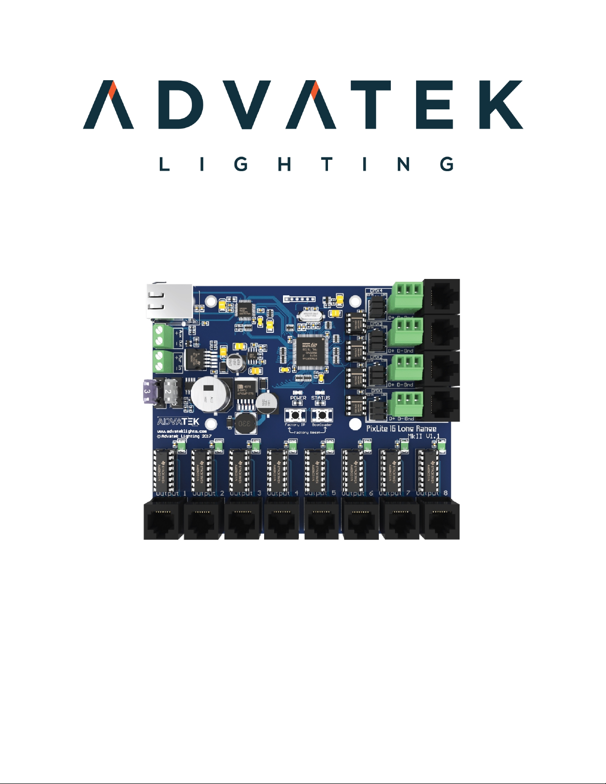
ADVATEK LIGHTING PixLite 16 Long Range Mk2 User manual
- 1 -
www.advateklights.com PixLite 16 Long Range Mk2 User Manual V210222
PixLite 16 Long Range Mk2 User Manual
Hardware Rev 1.0 - 1.1

- 2 -
www.advateklights.com PixLite 16 Long Range Mk2 User Manual V210222
1 - Table of Contents
1 - Table of Contents 2
2 - Introduction 4
3 - Safety Notes 5
4 - Installation 6
4.1 - Supplying Power 6
4.2 - Receiver Output Fuses & Power Injection 7
4.3 - Transmitter Logic Power 7
4.4 - Control Data 8
4.5 - Data Outputs 8
4.6 - Connecting the Transmitter to Receivers 8
4.6.1 - Basic Connections 8
4.7 - Connecting Pixel LEDs 9
4.8 - Expanded Mode 10
5 - Network Configuration 12
5.1 - Network Layout 12
5.2 - IPAddressing 13
5.2.1 - Using a Router 13
5.2.2 - Using a Switch/Direct 14
5.2.3 - Forcing the Default IPAddress 15
6 - Operation 16
6.1 - Start-up 16
6.2 - Sending Data 16
6.3 - Outputs 16
6.3.1 - Pixel Outputs 16
6.3.2 - DMX512 Outputs 17
6.3.3 - Fan Output 18
6.4 - Hardware Test Pattern 19
7 - Firmware Updates 21
7.1 - Performing a Standard Update 21
7.2 - Performing a Recovery Firmware Update 22

- 3 -
www.advateklights.com PixLite 16 Long Range Mk2 User Manual V210222
8 - Specifications 23
8.1 - Operating Specifications 23
8.2 - Mechanical Specifications 23
9 - Troubleshooting 25
9.1 - LEDCodes 25
9.2 - No Power/Status LEDs 25
9.3 - No Pixel Control 26
9.4 - Other Issues 26
9.5 - Reset to Factory Defaults 26
10 - Disclaimer 27

- 4 -
www.advateklights.com PixLite 16 Long Range Mk2 User Manual V210222
2 - Introduction
This is the user manual for the PixLite 16 Long Range Mk2 pixel controller, hardware
version 1.0 - 1.1. The PixLite 16 Long Range Mk2 controllers convert E1.31 (sACN) or Art-
Net protocols from a lighting console, media server or computer lighting software into
various pixel LEDprotocols.
This controller is designed to overcome distance problems typically encountered
when running many pixels from a single location. The PixLite 16 Long Range Mk2 sends
differential data signals directly out of the controller which can be transmitted
reliably using any standard network cable at distances in excess of 300m (1000’). At
the receiver end, the differential signals are then converted back to signals suitable
for pixels. This system allows the user to distribute a large number of pixels from a
centralized pixel controller easily, without needing to worry about the typical signal
degradation problems.
The PixLite 16 Long Range Mk2 features an output capacity of up to 96 universes of
multicast/unicast E1.31 or Art-Net data. This combined with an advanced feature-set
and easy-to-use configuration software make the PixLite 16 Long Range Mk2 an
excellent choice for your pixel lighting application.
This manual covers physical aspects of the PixLite 16 Long Range Mk2 controller and
its essential setup steps only. Detailed information about its configuration options
can be found in the ‘PixLite Configuration Guide’. Other manuals and the PixLite
Configuration Guide may be downloaded from here:
www.advateklights.com/downloads

- 5 -
www.advateklights.com PixLite 16 Long Range Mk2 User Manual V210222
3 - Safety Notes
The board comes shipped in an anti- static bag and has several electrostatic
sensitive components on it. Appropriate anti-static measures should be observed
when handling the board. For example, you should never sit the controller on carpet,
and you should avoid touching components on the controller unnecessarily.

- 6 -
www.advateklights.com PixLite 16 Long Range Mk2 User Manual V210222
4 - Installation
4.1 - Supplying Power
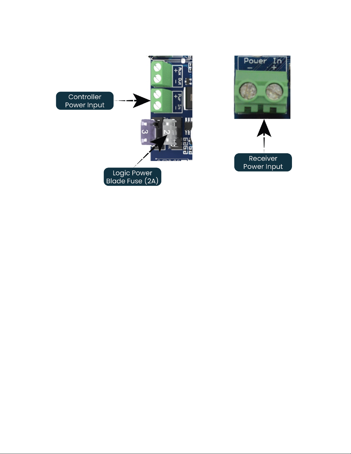
Power to the controller is applied via the power bank screw terminal connector,
located on the left-hand edge of the board, as shown in Figure 1 below. It is clearly
marked on the PCB with its polarity. Likewise, power to the receiver board is applied
via the large screw terminal connector on the left hand edge of the board labelled
‘Power In’. It is also clearly marked with polarity.
The PixLite 16 Long Range Mk2 transmitter control board requires a voltage of between
5V-24V DC and a max input current of 1.5A @ 5V.
The Long Range receiver is the board that actually powers the lights and thus requires
an appropriate power supply. Voltage to the power input is recommended to be
between 5V and 12V DC. The receiver will operate up to 24V DC, however attention
should be paid to cooling the controller when operating above 12V.
Note: It is the user’s responsibility to ensure that the power supply used matches the
voltage of the pixel fixture they are using and that it can supply the correct amount of
power/current.
The total maximum current through the receiver is 15 Amps.
- 7 -
www.advateklights.com PixLite 16 Long Range Mk2 User Manual V210222
Figure 1: Location of Power Input
4.2 - Receiver Output Fuses & Power Injection
Each individual output is protected by a mini blade fuse. The PixLite 16 Long Range
Mk2 receiver comes with 7.5A fuses by default. You may use any value of fuse, up to
and including 7.5A, depending on your specific application. Individual outputs should
not exceed 7.5A and the total current should not exceed 15A. If your application
requires more current than this, then you will need to inject power into the pixels
directly.
The number of pixels that can be physically powered through this device may not be
as high as the amount of pixel control data that is being output. There is no definitive
rule as to how many pixels can be powered from the controller, as it depends on the
type of pixel. You need to consider if your pixel load will draw more than 7.5A of
current and whether there will be too much voltage drop in the pixel load for it to only
be powered from one end. If you need to “inject power” we recommend bypassing
the controller’s power output pins entirely.
4.3 - Transmitter Logic Power
No on- board power configuration is required. Power to the logic circuitry is
automatically regulated from the power input. Simply connect your power supply of

- 8 -
www.advateklights.com PixLite 16 Long Range Mk2 User Manual V210222
between 5V and 24V DC to the power screw terminal, as shown in Figure 1 above. The
logic circuitry is protected by a 2A mini blade fuse.
4.4 - Control Data
Ethernet data is connected via a standard network cable into the RJ45 Ethernet jack
located on the left-hand side of the unit. The controller supports Streaming ACN
(sACN / E1.31) or Art-Net data.
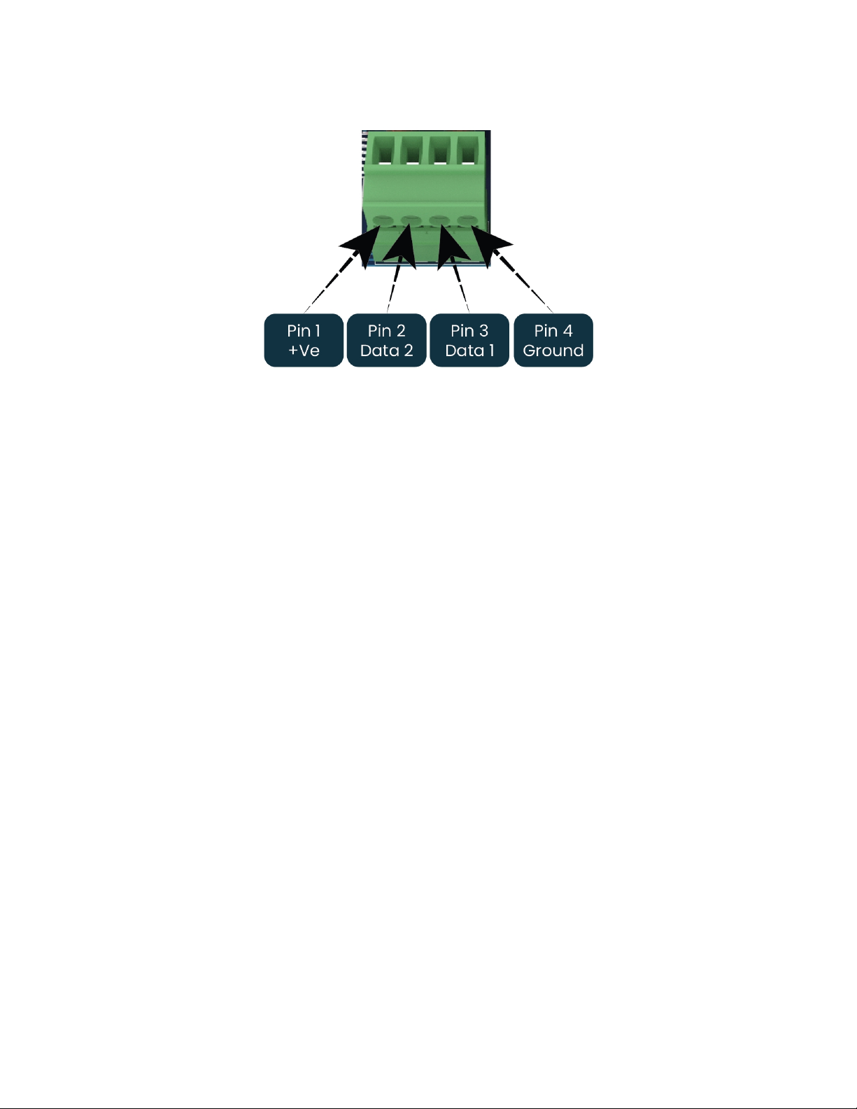
4.5 - Data Outputs
The receiver board outputs (RJ45 jacks) are located along the bottom edge of the
control board. There are 8 in total - each one containing 4 differential pairs. The pin-
out of the RJ45 jack is shown below. It is not important to understand this diagram for
most users, you simply use a standard network cable to connect the transmitter and
receiver boards.
Figure 2: Data RJ45 Pinout
4.6 - Connecting the Transmitter to Receivers
4.6.1 - Basic Connections
Receivers are connected to the transmitter via the RJ45 jacks along the bottom edge
of the control board. Each jack is labelled with its output number 1-8. These ports are
not network ports, and should not be connected to any networking equipment, as
shown in Figure 3 below. They are specifically designed to connect a PixLite
transmitter with a PixLite receiver. For this reason, the standard network cable you use
can be safely used in excess of 300m.

- 9 -
www.advateklights.com PixLite 16 Long Range Mk2 User Manual V210222
Figure 3: Correct equipment to use
A typical setup is shown in Figure 4 below, which also shows how many pixels can be
run off each output.
Figure 4: Connecting Receivers to Transmitter
4.7 - Connecting Pixel LEDs
The pixel lights are connected directly via the 2 pluggable screw terminal connectors
on the receivers . Each connector is labelled with its output channel number (1-2) and

- 10 -
www.advateklights.com PixLite 16 Long Range Mk2 User Manual V210222
pin 1 is also clearly marked. Simply wire your lights into each screw terminal and then
plug them into the mating sockets.
Warning: It is very important not to short +ve onto the clock or data lines when using
pixels greater than 5V. Note that this can also happen from poor waterproofing when
rain shorts the higher voltage onto either of those wires in your pixels/wiring.
The cable length between the output and the first pixel should not exceed 15m.
Figure 5 shows the pin-out of the pixel output connectors.
Figure 5: Normal Mode Pixel Output Pinout
4.8 - Expanded Mode
If your pixels do not have a clock line, you may optionally activate expanded mode on
the controller, via the Advatek Assistant. In expanded mode, the clock lines are used
as data lines instead. This means the controller effectively has twice as many pixel
outputs (32), but half as many pixels per output can be run.
It is advantageous to use this mode with data-line only pixels compared to normal
mode, because the refresh rates will be improved. Pixels that only use a data line are
generally slow compared to clocked pixels, so improving the refresh rate is beneficial.
This is especially important if you are using close to the maximum number of pixels
per output.
The pinout for expanded mode is shown in Figure 6 below.
- 11 -
www.advateklights.com PixLite 16 Long Range Mk2 User Manual V210222
Figure 6: Expanded Mode Pixel Output Pinout

- 12 -
www.advateklights.com PixLite 16 Long Range Mk2 User Manual V210222
5 - Network Configuration
5.1 - Network Layout
Figure 7: Network Layout using a Server and Switch
Figure 7 shows a typical network topology for the PixLite 16 Long Range Mk2 controller
(s) LAN. Installations using multicast sACN will benefit from the use of IGMP Snooping
enabled network equipment when there are more multicast universes on the network
than any one PixLite is using. If there are more than 96 universes of multicast sACN on
the network then IGMP Snooping is mandatory.
- 13 -
www.advateklights.com PixLite 16 Long Range Mk2 User Manual V210222
Having a router on the network is not mandatory but is useful for IP address
management with DHCP (see Section 5.2.1). When IGMP snooping, a router may also
be required (depending on your network switch functionality).
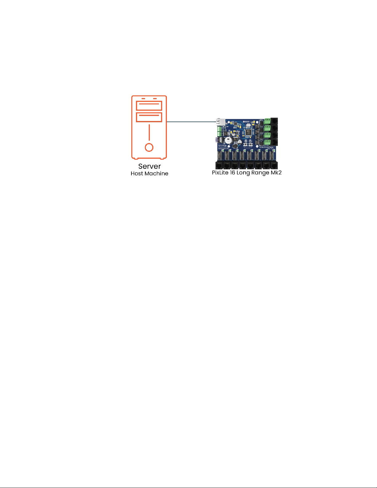
Figure 8: Network Layout using Only a Server
In a single controller installation, it may be preferable to connect the controller
directly to the host machine, as shown in Figure 8. A crossover cable is not required in
this case, but it may be used if desired.
The controller(s) can be integrated straight into any pre-existing LAN such as your
media, home or office network, the above diagrams are only provided as examples.
5.2 - IPAddressing
5.2.1 - Using a Router
Routers have a DHCP server in them – this means they will tell a device plugged into
them what IP address to use, if asked.
DHCP is always enabled by default on a PixLite controller so it can immediately
connect to any existing network with a router. However, you may instead prefer to
assign a static IP address once communications have been established via the
Advatek Assistant. If the controller is in DHCP mode and is not assigned an IP address
by a DHCP server, it will timeout after a short time (approximately 30 seconds) and
default to a static IP of ‘192.168.0.50’.
If DHCP mode is enabled, both the status and power LEDs will flash together until the
controller receives an IP address or times out to its default IP. After this, the power LED
will remain on solid and the status LED will flash, indicating it is in run mode and
ready for use.

- 14 -
www.advateklights.com PixLite 16 Long Range Mk2 User Manual V210222
If a static IP address is assigned to the controller, then the power LED will be solid from
power up.
5.2.2 - Using a Switch/Direct
It may be necessary to connect the controller to a network without a DHCP server or
even directly to the host machine instead of using a router. In this case (for first time
configuration) you will need to ensure that the network adapter of your computer is
set in the IP range that the controller will default to (controller defaults to 192.168.0.50).
This means your PC’s IP should be 192.168.0.xxx where xxx is anything between 1 and
254, other than 50. The subnet mask on your PC should be set to 255.255.255.0.
Note: The Advatek Assistant software will automatically detect if a controller is
connected to the network, even if it is outside the adapter’s IP address range. It will
prompt you to change the IP settings if this situation is discovered.
Once you can successfully discover the controller in the Advatek Assistant, we
recommended setting the controller to a static IP address other than the default.
Figure 9 shows a screenshot of typical computer network settings to communicate
with a PixLite 16 Long Range Mk2 controller for the first time without a router.

- 15 -
www.advateklights.com PixLite 16 Long Range Mk2 User Manual V210222
Figure 9: PC Network Configuration
5.2.3 - Forcing the Default IPAddress
In the event that you forget the IP of a controller and you can’t see it in the Advatek
Assistant, it can be forced to its default IP. A simple procedure can be employed on
power up:
1. Hold down the “Factory IP” button on the PCB and power up the controller
2. After a few seconds release the button. The controller’s IP address will now
be 192.168.0.50.
You should now be able to set up your PC’s network settings to find the controller at
this IP and change the IP settings to a preferred static IP address.

- 16 -
www.advateklights.com PixLite 16 Long Range Mk2 User Manual V210222
6 - Operation
6.1 - Start-up
Upon applying power, the controller will quickly begin outputting data to the receivers,
commanding the pixels to turn off. If no data is being sent to the controller then the
pixels will remain turned off until valid data is received. During normal operation, on
the controller the green power LED will remain on solid and the red status LED will flash
to indicate the controller is running and outputting any received Ethernet data to the
receivers.
6.2 - Sending Data
Input data is sent from the control PC/server/lighting console to the controller via
Ethernet using a “DMX over IP” protocol such as sACN (E1.31) or Art-Net.
If no incoming data is received for a few seconds, the pixels will be turned off
automatically unless that option has been disabled in your configuration. If the pixels
are not controllable then make sure you have selected the correct pixel IC type in the
Advatek Assistant under the ‘LEDs’ tab.
6.3 - Outputs
6.3.1 - Pixel Outputs
Each of the 8 controller RJ45 output jacks can drive up to 12 universes of data. This
allows for a total of up to 96 universes to be driven out of the one controller (in
addition to 4 DMX512 Universe outputs).
The refresh rate of the pixels will depend on the operating frequency of the specific
pixel chip type. Higher speed pixels will result in higher refresh rates. Pixels with no
clock line will have a relatively low refresh rate when a significant number of pixels
are used on a single output. Advatek recommends the use of clocked pixels
whenever using a large number of sequential pixels on any output. Typically, the
refresh rate can vary from 20 fps at the low end on data only pixels and up to 100+ fps
at the higher end.

- 17 -
www.advateklights.com PixLite 16 Long Range Mk2 User Manual V210222
6.3.2 - DMX512 Outputs
The PixLite 16 Long Range Mk2 provides 4 DMX512 outputs which can be accessed
either by pluggable screw terminal connectors or by RJ45 jacks. The hardware layer
on which the DMX512 protocol operates is the RS485 electrical communications
standard. This is a differential transmission system consisting of a two- wire
differential signal pair and a ground connection. Ideally the differential signals
should be wired into a twisted pair cable. The D+, D- and ground connections are
clearly labelled on the PCB for the screw terminal connectors.
These outputs act as individual DMX512 universe outputs, effectively providing the
user with an E1.31 or Art-Net to 4 x DMX512 bridge (in addition to the normal pixel
outputs).
DMX512 signal data is also connected via the four vertical RJ45 sockets. On-board
jumper links (circled in Figure 10 below) allow each RJ45 DMX output to use either the
‘ESTA’ wiring or the ‘LOR’ wiring configuration. (All controllers are shipped with the links
in the ‘ESTA’ configuration.)
Please note that DMX outputs are not electrically isolated.
All these connectors and jumper links are located on the far right-hand edge of the
controller as shown in Figure 10 below.
Figure 10: Location of DMXOuputs

- 18 -
www.advateklights.com PixLite 16 Long Range Mk2 User Manual V210222
Below is the RJ45 socket pin-out for the DMX connectors when the “ESTA” wiring is
selected:
Figure 11: ESTAPinout
Below is the RJ45 socket pin-out for the DMX connectors when the “LOR” wiring is
selected:
Figure 12: LORPinout
6.3.3 - Fan Output
The controller features an auxiliary fan output that can power an external fan(s) for
cooling the enclosure that the controller is mounted in, as shown in Figure 13 below.
This feature is useful in order to keep the temperature regulated when you mount the
controller and a high wattage power supply together in a small, confined space.
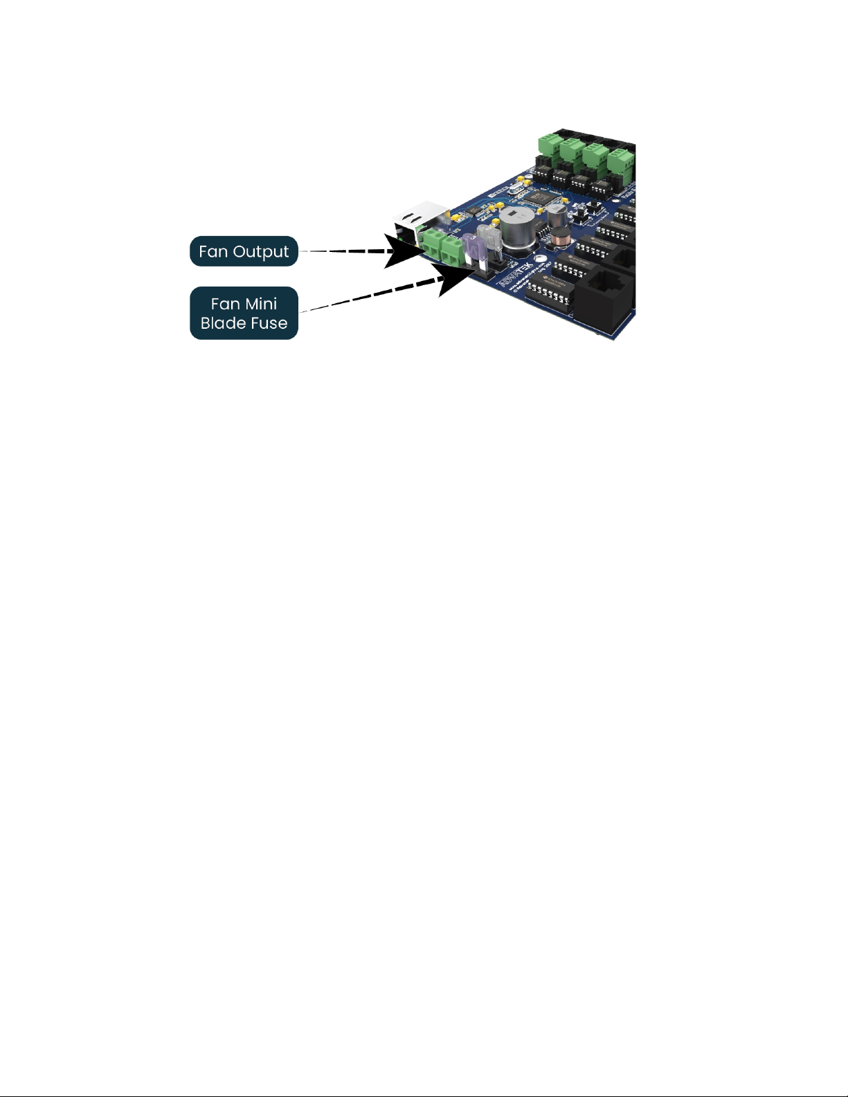
- 19 -
www.advateklights.com PixLite 16 Long Range Mk2 User Manual V210222
Figure 13: Location of Fan Output
The output voltage of the fan output is the same as the input voltage. So, to run a 12V
fan for example, you would need to use a 12V input voltage. The fan output can supply
up to 15W of continuous output power and is PWM controlled. The output is protected
by a 3A mini-blade fuse.
Basic operation is as follows: In the Advatek Assistant, the user can set a target
temperature that the enclosure will ideally not exceed. The controller will then
automatically adjust the fan speed based on the current temperature as measured
by the controller’s on-board temperature sensor.
For example, if the target temperature is set at 30°C then sometime before that
temperature, the controller will turn the fan on and slowly ramp up the speed until it
reaches 100% if required, in an attempt to maintain the temperature either at or below
30°C. If the temperature decreases the fan will slow down. The controller will attempt
to keep the temperature below the set point. If the detected temperature reaches the
set temperature, the fan output will be on 100% at this point.
6.4 - Hardware Test Pattern
The controller features a built-in test pattern to assist in troubleshooting during an
installation. To put the controller into this mode, press and hold the ‘Factory IP’ button
for 3 seconds (after the controller is already running) or turn it on remotely from the
“Test” tab in the Advatek Assistant.
The controller will then enter the test pattern mode, where different test patterns are
available as described in the table below. The pattern will display the test pattern on
all pixels on each of the pixel outputs and any enabled DMX512 outputs
- 20 -
www.advateklights.com PixLite 16 Long Range Mk2 User Manual V210222
simultaneously. Pressing the 'Factory IP' button while in test mode will move through
each of the patterns successively in one continuous loop.
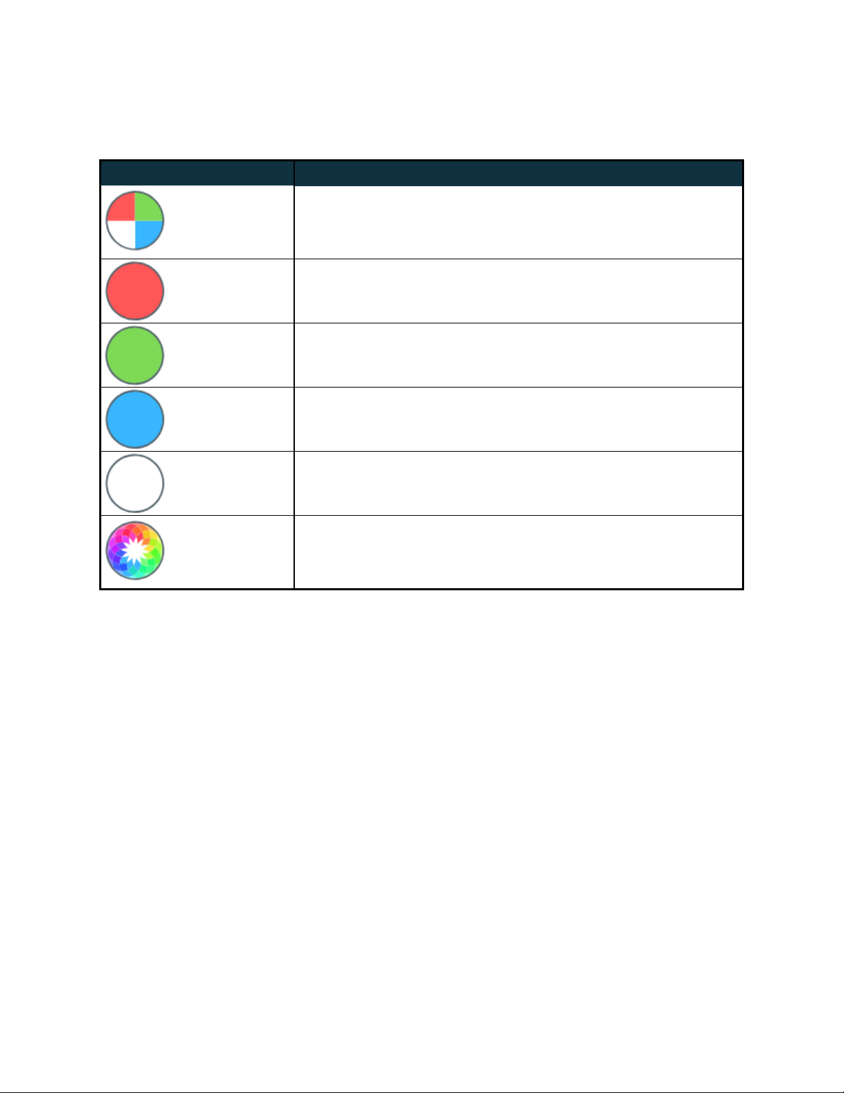
Test Operation
Colour
Cycle
Outputs will cycle automatically through the red, green,
blue and white colours at fixed intervals. Pressing the but-
ton moves to the next mode.
Red Solid Red
Green Solid Green
Blue Solid Blue
White Solid White
Colour
Fade
Outputs will slowly move through a full continuous colour
fade. Pressing the button will loop back to the original col-
our cycle test mode.
To exit the test mode press and hold the ‘Factory IP’ button down again for 3 seconds
and then release.
The hardware test requires that the pixel driver chip type and number of pixels per
output are set correctly in the Advatek Assistant. In this way you can test if that part of
your configuration is correct and isolate other possible problems with the incoming
Ethernet data side.
This manual suits for next models
1
Table of contents


