advidia VP-8-V2 User manual

VP-8-V2 and VP-16-V2 Series Encoder
User Manual

VP-8-V2 and VP-16-V2 Series Encoder
·
User Manual
1
About this Manual
This Manual is applicable to VP-8-V2 AND VP-16-V2 Series Encoder.
The Manual includes instructions for using and managing the product. Pictures, charts, images
and all other information hereinafter are for description and explanation only. The information
contained in the Manual is subject to change, without notice, due to firmware updates or other
reasons. Please find the latest version in the company website
Please use this user manual under the guidance of professionals.
Legal Disclaimer
REGARDING TO THE PRODUCT WITH INTERNET ACCESS, THE USE OF PRODUCT SHALL BE WHOLLY
AT YOUR OWN RISKS. OUR COMPANY SHALL NOT TAKE ANY RESPONSIBILITES FOR ABNORMAL
OPERATION, PRIVACY LEAKAGE OR OTHER DAMAGES RESULTING FROM CYBER ATTACK, HACKER
ATTACK, VIRUS INSPECTION, OR OTHER INTERNET SECURITY RISKS; HOWEVER, OUR COMPANY
WILL PROVIDE TIMELY TECHNICAL SUPPORT IF REQUIRED.
SURVEILLANCE LAWS VARY BY JURISDICTION. PLEASE CHECK ALL RELEVANT LAWS IN YOUR
JURISDICTION BEFORE USING THIS PRODUCT IN ORDER TO ENSURE THAT YOUR USE CONFORMS
THE APPLICABLE LAW. OUR COMPANY SHALL NOT BE LIABLE IN THE EVENT THAT THIS PRODUCT
IS USED WITH ILLEGITIMATE PURPOSES.
IN THE EVENT OF ANY CONFLICTS BETWEEN THIS MANUAL AND THE APPLICABLE LAW, THE
LATER PREVAILS.

VP-8-V2 and VP-16-V2 Series Encoder
·
User Manual
2
Regulatory Information
FCC Information
FCC compliance: This equipment has been tested and found to comply with the limits for a Class
A digital device, pursuant to part 15 of the FCC Rules. These limits are designed to provide
reasonable protection against harmful interference when the equipment is operated in a
commercial environment. This equipment generates, uses, and can radiate radio frequency
energy and, if not installed and used in accordance with the instruction manual, may cause
harmful interference to radio communications. Operation of this equipment in a residential area
is likely to cause harmful interference in which case the user will be required to correct the
interference at his own expense.
FCC Conditions
This device complies with part 15 of the FCC Rules. Operation is subject to the following two
conditions:
1. This device may not cause harmful interference.
2. This device must accept any interference received, including interference that may cause
undesired operation.
EU Conformity Statement
This product and - if applicable - the supplied accessories too are marked with "CE"
and comply therefore with the applicable harmonized European standards listed
under the EMC Directive 2004/108/EC, the RoHS Directive 2011/65/EU.
2012/19/EU (WEEE directive): Products marked with this symbol cannot be disposed of
as unsorted municipal waste in the European Union. For proper recycling, return this
product to your local supplier upon the purchase of equivalent new equipment, or
dispose of it at designated collection points. For more information see: www.recyclethis.info
2006/66/EC (battery directive): This product contains a battery that cannot be disposed
of as unsorted municipal waste in the European Union. See the product
documentation for specific battery information. The battery is marked with this
symbol, which may include lettering to indicate cadmium (Cd), lead (Pb), or mercury (Hg). For
proper recycling, return the battery to your supplier or to a designated collection point. For more
information see: www.recyclethis.info
Industry Canada ICES-003 Compliance
This device meets the CAN ICES-3 (A)/NMB-3(A) standards requirements.

VP-8-V2 and VP-16-V2 Series Encoder
·
User Manual
3
Safety Instruction
These instructions are intended to ensure that user can use the product correctly to avoid danger
or property loss.
The precaution measure is divided into “Warnings” and “Cautions”
Warnings: Serious injury or death may occur if any of the warnings are neglected.
Cautions: Injury or equipment damage may occur if any of the cautions are neglected.
Warnings
●
Proper
configuration of all passwords and other security settings is the responsibility of the installer
and/or end-user.
●
In the use of the product, you must be in strict compliance with the electrical safety
regulations of the nation and region. Please refer to technical specifications for detailed
information.
●
Input voltage should meet both the SELV (Safety Extra Low Voltage) and the Limited Power
Source with 100 to 240 VAC or 12 VDC according to the IEC60950-1 standard. Please refer to
technical specifications for detailed information.
●
Do not connect several devices to one power adapter as adapter overload may cause
over-heating or a fire hazard.
●
Please make sure that the plug is firmly connected to the power socket.
●
If smoke, odor or noise rise from the device, turn off the power at once and unplug the power
cable, and then please contact the service center.
Warnings Follow these
safeguards to prevent
serious injury or death.
Cautions Follow these
precautions to prevent
potential injury or material
damage.

VP-8-V2 and VP-16-V2 Series Encoder
·
User Manual
4
Preventive and Cautionary Tips
Before connecting and operating your device, please be advised of the following tips:
•
Ensure unit is installed in a well-ventilated, dust-free environment.
•
Unit is designed for indoor use only.
•
Keep all liquids away from the device.
•
Ensure environmental conditions meet factory specifications.
•
Ensure unit is properly secured to a rack or shelf. Major shocks or jolts to the unit as a result
of dropping it may cause damage to the sensitive electronics within the unit.
•
Use the device in conjunction with an UPS if possible.
•
Power down the unit before connecting and disconnecting accessories and peripherals.
•
Improper use or replacement of the battery may result in hazard of explosion. Replace with
the same or equivalent type only. Dispose of used batteries according to the instructions
provided by the battery manufacturer.

VP-8-V2 and VP-16-V2 Series Encoder
·
User Manual
5
TABLE OF CONTENTS
Product Key Features......................................................................................................................................... 7
Chapter 1
Introduction ........................................................................................................................... 8
1.1
Front Panel ...................................................................................................................................... 8
1.2
Rear Panel ........................................................................................................................................ 8
1.3
Alarm Connections .......................................................................................................................... 9
1.3.1
Alarm Input Connections ..................................................................................................... 9
1.3.2
Alarm Output Connections ................................................................................................ 10
Chapter 2
Access to V2 Encoder via Web Browser .............................................................................. 11
2.1
Installing Web Components ........................................................................................................... 11
2.2
Main Page ...................................................................................................................................... 13
Chapter 3
Live View .............................................................................................................................. 15
3.1
Starting Live View .......................................................................................................................... 15
3.1.1
Main/Sub Stream Live View ............................................................................................... 16
3.1.2
Full-screen Mode ............................................................................................................... 16
3.2
Capturing the Picture..................................................................................................................... 17
3.3
Operating PTZ Control ................................................................................................................... 17
3.3.3
Operating PTZ Movement .................................................................................................. 17
3.3.4
Setting/Calling a Preset ...................................................................................................... 18
3.3.5
Setting/Calling a Patrol....................................................................................................... 20
3.4
Configuring Video Parameters ....................................................................................................... 21
Chapter 4
Device Configuration ........................................................................................................... 23
4.1
Local Configuration ........................................................................................................................ 23
4.2
Device Parameters ......................................................................................................................... 24
4.2.1
Configuring Time Settings .................................................................................................. 24
4.2.2
Configuring Packet Time of Recording ............................................................................... 26
4.3
Network Settings ........................................................................................................................... 26
4.3.1
Configuring TCP/IP Settings ................................................................................................ 26
4.3.2
Configuring Port Settings ................................................................................................... 27
4.3.3
Configuring DDNS Settings ................................................................................................. 28
4.3.4
Configuring PPPoE Settings ................................................................................................ 29
4.3.5
Configuring Email Settings ................................................................................................. 30
4.3.6
Configuring SNMP Settings ................................................................................................ 32
4.3.7
Configuring UPnP
TM
Settings .............................................................................................. 33
4.3.8
Configuring HTTPS
Settings ................................................................................................ 34
4.3.9
Configuring Multicast Address ........................................................................................... 36
4.3.10
Configuring Remote Alarm Host ........................................................................................ 36
Chapter 5
Camera Settings ................................................................................................................... 38
5.1
Configuring OSD Settings ............................................................................................................... 38
5.1.1
Configuring Display Settings ............................................................................................... 38
5.1.2
Configuring Text Overlay .................................................................................................... 39
5.2
Configuring Video Settings ............................................................................................................ 41

VP-8-V2 and VP-16-V2 Series Encoder
·
User Manual
6
5.3
Configuring and Handling Alarms .................................................................................................. 42
5.3.3
Configuring Motion Detection ........................................................................................... 42
5.3.4
Configuring External Alarm Input ....................................................................................... 48
5.3.5
Configuring Video Loss Alarm ............................................................................................ 49
5.3.6
Configuring Video Tempering Alarm .................................................................................. 50
5.3.7
Handling Exception ............................................................................................................ 51
5.4
Configuring Privacy Mask .............................................................................................................. 52
Chapter 6
Managing User Accounts ..................................................................................................... 54
1.1
Adding a User ................................................................................................................................ 54
6.2
Modifying a User ........................................................................................................................... 55
6.3
Deleting a User .............................................................................................................................. 56
Chapter 7
Maintenance ........................................................................................................................ 58
7.1
Viewing Device Information .......................................................................................................... 58
7.2
Maintenance.................................................................................................................................. 58
7.2.1
Restarting the Device ......................................................................................................... 59
7.2.2
Restoring Default Settings .................................................................................................. 59
7.2.3
Importing/Exporting Configuration Files ........................................................................... 60
7.2.4
Upgrading the System ........................................................................................................ 60
Chapter 8
Specification ........................................................................................................................ 61
FAQ………………………………………………………………………………………………………………………………………………………62

VP-8-V2 and VP-16-V2 Series Encoder
·
User Manual
7
Product Key Features
General
Connectable to HD-TVI and analog cameras
Connectable to the Coaxitron camera/dome with long transmission distance
Each channel supports dual-stream with up to 1080p resolution
Independent configuration for each channel, including resolution, frame rate, bit rate, image
quality, etc
Encoding for both video stream and video and audio stream; audio and video
synchronization during composite stream encoding
Watermark technology
Monitoring
Motion detection, video-tampering detection, video exception alarm, video loss alarm and
VCA alarm functions
Privacy mask
Several PTZ protocols supported; PTZ preset, patrol and pattern
Alarm and Exception
Configurable arming time of alarm input/output
Alarm triggers, audio alarm, notifying surveillance center, sending email and alarm output
VCA detection alarm (line crossing detection and intrusion detection) is supported by client
software
Support coaxial alarm.
Network Functions
1 self-adaptive 10M/100M/1000M network interface
IPv6 is supported
TCP/IP protocol, PPPoE, DHCP, DNS, DDNS, NTP, SADP, SMTP, SNMP, NFS, iSCSI, UPnP™ and
HTTPS are supported
Extranet access by HiDDNS
TCP, UDP and RTP for unicast
Auto/Manual port mapping by UPnP
TM
Remote search, playback, download, locking and unlocking the record files, and
downloading files broken transfer resume
Remote parameters setup; remote import/export of device parameters
Remote viewing of the device status, system logs and alarm status
Remote keyboard operation
Remote program upgrading
Remote system restart and shutdown
Alarm and exception information can be sent to the remote host

VP-8-V2 and VP-16-V2 Series Encoder
·
User Manual
8
Remotely start/stop recording
Remotely start/stop alarm output
Remote PTZ control
Remote JPEG capture
Two-way audio and voice broadcasting
Embedded WEB server
Chapter 1 Introduction
1.1
Front Panel
VP-8-V2/VP-16-V2:
Figure 1. 1 VP-8-V2/VP-16-V2 Front Panel
Table 1. 1 Indicator Description
Indicator Description
1 POWER Lights in green when the device is powered on.
2 Not Used
3 Tx/Rx 1. Does not light when the network is not connected;
2. Blinks in green when the data is transmitting / receiving;
3. Blinks at higher frequency when the data for transmitting /
receiving is larger.
1.2
Rear Panel
VP-8-V2:
VP-8-V2 and VP-16-V2 Series Encoder
·
User Manual
9
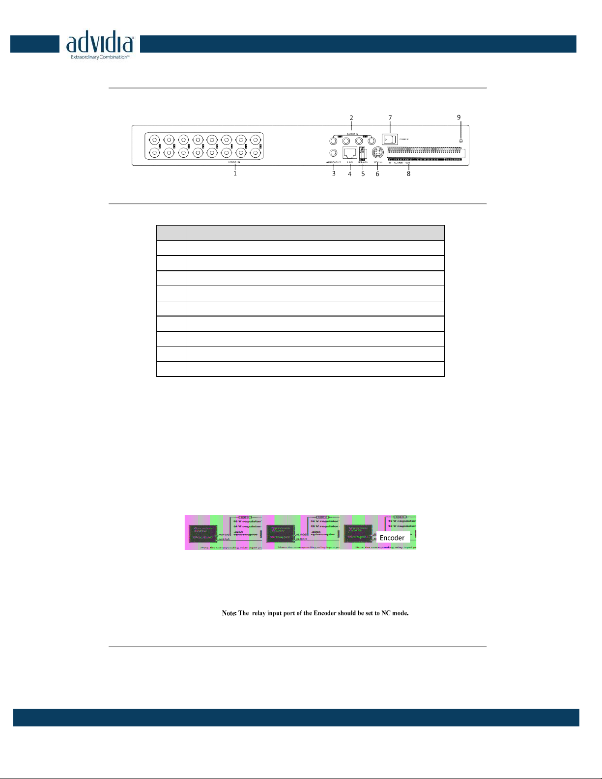
Figure 1. 2 VP-8-V2 Rear Panel
VP-16-V2:
Figure 1. 3 VP-16-V2
Table 1. 2 Interface Description
Description
1
VIDEO IN
2
AUDIO IN, RCA Connector
3
AUDIO OUT, RCA Connector
4
LAN Network Interface
5
RS-485 Serial Interface
6
12 VDC Power Input
7
Power Switch
8
ALARM IN and ALARM OUT
9
GND
1.3 Alarm Connections
1.3.1 Alarm Input Connections
VP-8-V2 AND VP-16-V2 supports the open/close
relay input as the alarm input mode. For the alarm input signal
not in open/close relay signal mode, please follow the connections shown as below:
Alarm input connections for Emerson Alarm:
Figure 1. 4 Alarm Input Connections for Emerson Alarm
Alarm input connections for Normal Alarm:
VP-8-V2 and VP-16-V2 Series Encoder
·
User Manual
10
Figure 1. 5 Alarm Input Connections for Normal Alarm
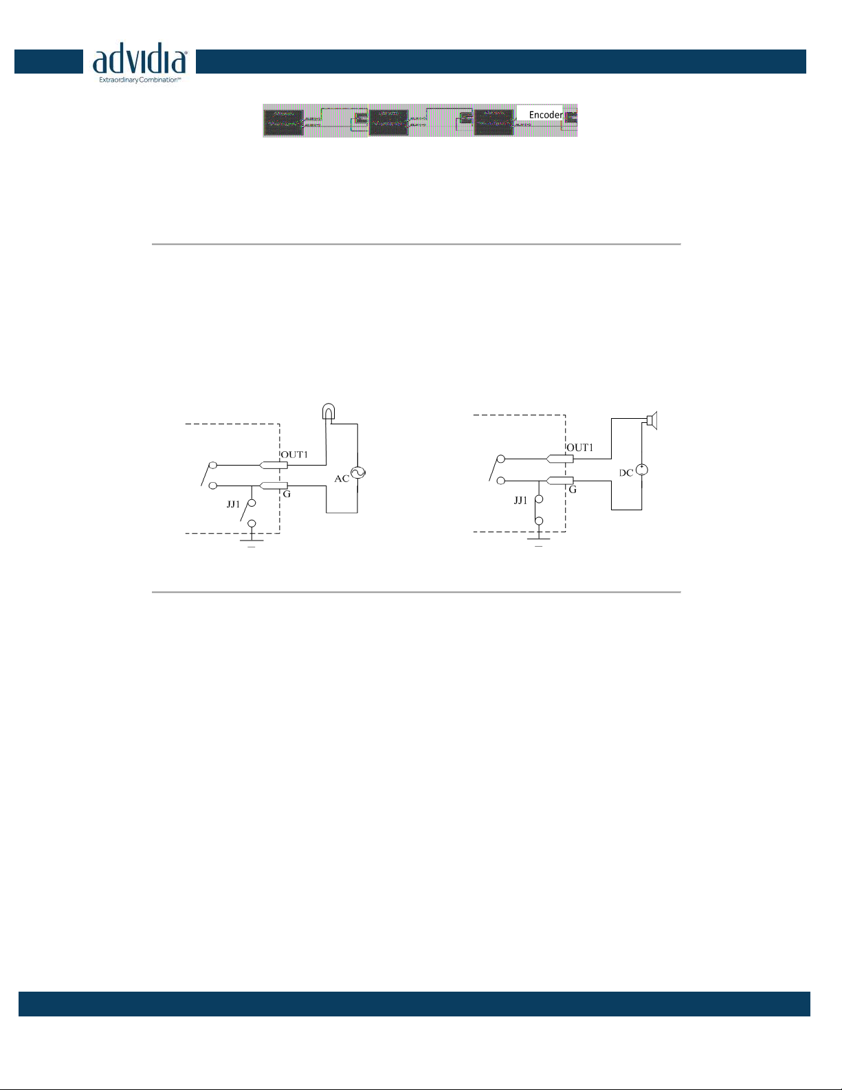
1.3.2 Alarm Output Connections
VP-8-V2 AND VP-16-V2 supports the open/close relay input as the alarm output mode. The alarm input can be
selected to NO or NC. Different alarm output connection methods are applied to the AC or DC load. Please refer
to the following diagram:
Alarm output connections diagram:
Figure 1. 6 Alarm Output Connections
Please note the different connections of JJ1 shown above.
For DC load, JJ1can be safely used both in NC and NO methods, and it is recommended to use within the limit of
12V/1A. For external AC input, JJ1 must be open. The motherboard provides two jumpers, each corresponding to
one alarm output. And both of two jumpers are factory set to be connected.

VP-8-V2 and VP-16-V2 Series Encoder
·
User Manual
11
Chapter 2 Access to V2 Encoder via Web
Browser
Steps:
1. Power on the encoder, and connect the encoder to the network.
2. Input the IP address into the address bar of the web browser, and click Enter to enter the activation
interface.
The default IP address of the network encoder is 192.0.0.64. You are recommended to change
the default IP address after your access.
3. Default username is admin Default password is 12345.
The VP-8-V2 AND VP-16-V2 can also be accessed by WEB Browser for configuration and operation. The supported
WEB browsers include: Internet Explorer 6/7/8/9, Firefox 3.5 and above, Chrome 8 and above, Safari 5.0.2 and
above, Windows XP SP1 and above (32-bit).
Before you start:
Before access, you need to configure the network settings of device according to Chapter 3.
Connect the device to the LAN, and prepare a PC connected to the same LAN with the device.
The factory default IP address of the device is 192.0.0.64.
2.1 Installing Web Components
Steps:
1. Open WEB browser, input the IP address of VP-8-V2 AND VP-16-V2 (e.g.,
http://192.0.0.64) and then press
the Enter key on PC. The system will display the login interface.
When the HTTPS feature is enabled, the system uses the HTTPS login mode (e.g., https://192.0.0.64) by default.
You can also input http://IP address/index.asp (e.g., http://192.0.0.64/index.asp) if you want to use HTTP mode to
log into the device.

VP-8-V2 and VP-16-V2 Series Encoder
·
User Manual
12
Figure 2. 1 Login Page
Input the user name and the password to log into the system.
In the Login dialog box, if you have entered the wrong password for 7 times for the admin user or 5 times for the
normal user, the current user account will be locked for30 seconds.
2. On the main page of VP-8-V2 AND VP-16-V2, you need to download and install the plug-in.
(1) Click on the live view panel by following the hints on the screen.
Figure 2. 2 Download and Install Plug-in
(2) Click Run or Save on the pop-up warning message box.
Figure 2. 3 Run Web Components
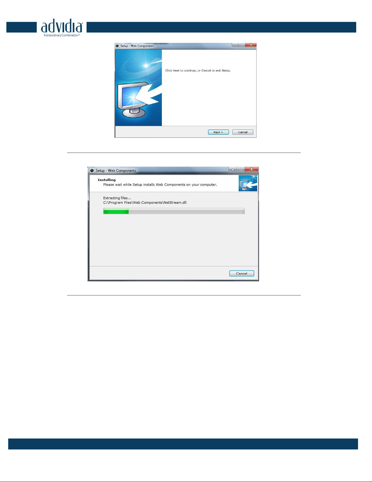
(3) Click Next on the pop-up Setup dialog box.
VP-8-V2 and VP-16-V2 Series Encoder
·
User Manual
13
Figure 2. 4 Click Next
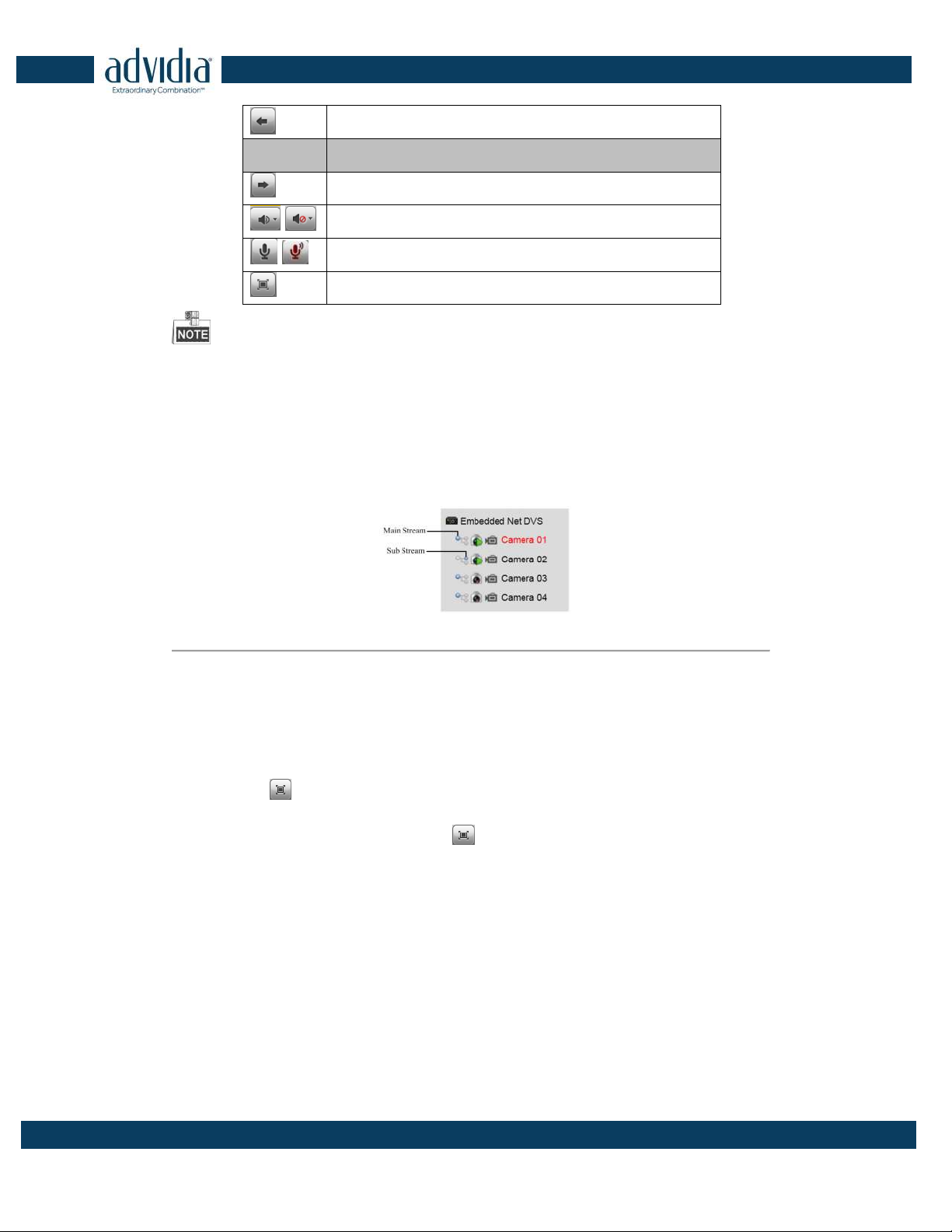
(4) When the installation completes, click Finish to finish the installation of Web Components.
Figure 2. 5 Install the Web Components
2.2 Main Page
After successful login, you will enter the main page automatically.

VP-8-V2 and VP-16-V2 Series Encoder
·
User Manual
14
Figure 2. 6 Main Page
Description of the live view page:
Menu Bar: Enter the Live View, Playback, Log and Configuration page respectively.
Device List: Display the connected encoder and its channels.
Window-division: 1/4/9/16split screen modes.
Live Video Window: Display the live video of the current camera.
Toolbar: Realize functions in live view mode, e.g., live view, capture, recording, audio on/off, two-way audio, etc.
PTZ Control: Realize PTZ control of the camera (supports PTZ function), and the lighter and wiper control.
Preset Setting/Calling: Set and call the preset for the camera (supports PTZ function).
Video Parameters Settings: Configure the brightness, contrast, hue and saturation of the live video.

VP-8-V2 and VP-16-V2 Series Encoder
·
User Manual
15
Chapter 3 Live View
Live view shows you the video image getting from the connected camera in real time. After successful login, the
system will enter the live view page automatically.
3.1 Starting Live View
Steps:
1. In the live view window, select a playing window by clicking the mouse.
2. Double click a camera from the device list to start the live view.
Figure 3. 1 Start Live View
3. You can click the button on the toolbar to start the live view of all cameras on the device list.
Refer to the following table for the description of buttons on the live view window:
Table 3. 1 Description of Toolbar
Icon Description
Select the window-division mode with 1/4/9 split screens available
/ Start/Stop live view
Capture pictures in live view mode
/ Manually start/stop recording
Enable e-PTZ
VP-8-V2 and VP-16-V2 Series Encoder
·
User Manual
16
Previous page
Icon Description
Next page
/ Audio on/off
/ Start/Stop two-way audio
Switch to full-screen live view mode.
Before using two-way audio function or recording with audio, please select the Video Type to Video & Audio on
Section Configuring Video Settings.
3.1.1 Main/Sub Stream Live View
You can select the main stream or sub stream for live view by clicking the corresponding icon as shown below:
Figure 3. 2 Main Stream/Sub Stream for Live View
The main stream gets higher video quality while the sub stream requires lower bandwidth.
3.1.2 Full-screen Mode
You can click the button on the toolbar or double click on the live video to switch to the full-screen view
mode. To switch back to the normal mode, click the
or double click on the live video again.
Please refer to the following section for more information:
1. Capturing pictures on Section Capturing the Picture. .
2. Configuring recording on
3. .
4. Setting the image quality of live view on Section Local Configuration.
5. Setting the saving path for the recorded video files and captured pictures on Section Local Configuration.
6. Setting the OSD text on live video on Section Configuring OSD Settings.
VP-8-V2 and VP-16-V2 Series Encoder
·
User Manual
17
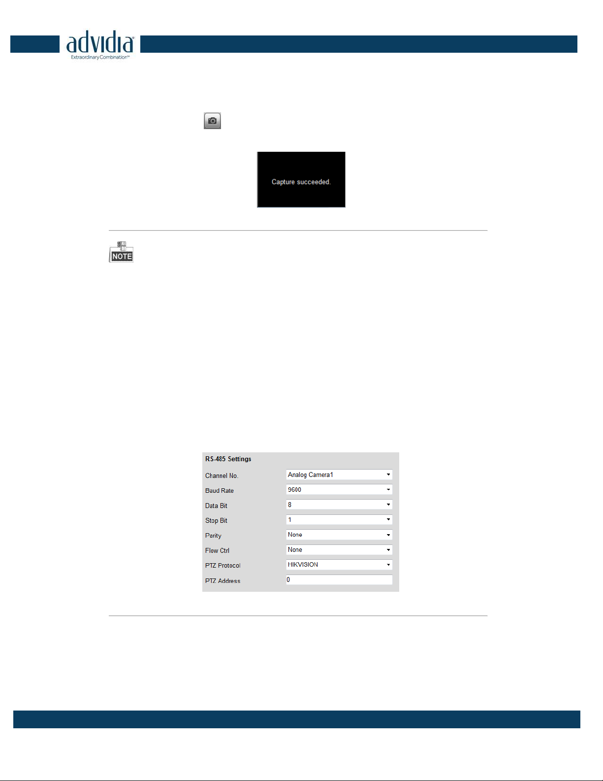
3.2 Capturing the Picture
In live view mode, click the button on the toolbar to capture the live pictures.
When the picture is captured, the following pop-up message box will appear at the lower right corner.
Figure 3. 3 Picture Capture Succeeded
The saving path for the captured pictures can be set at the Configuration > Local Configuration page.
The image is saved as a JPEG file on your computer.
3.3 Operating PTZ Control
Before you start:
1. Make sure the encoder is connected with the camera/dome which supports PTZ function. Connect the R+
and R- terminals of the pan/tilt unit or speed dome to RS-485 D+ and RS-485 D- terminals of the VP-8-V2
AND VP-16-V2 respectively.
2. The baud rate, PTZ control and address configured in the RS-485 Settings interface (Remote Configuration >
Serial Port Settings > 485 Serial Port), as shown in Figure 6.3, must be the same with the parameters of the
connected pan/tilt unit or speed dome.
Figure 3. 4 RS-485 Settings
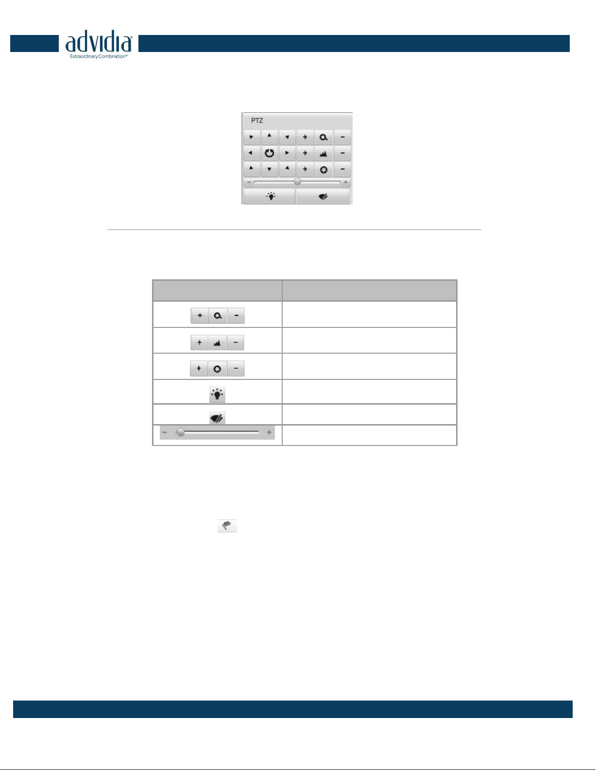
3.3.3 Operating PTZ Movement
In live view mode, you can use the PTZ control buttons to realize pan/tilt/zoom control of the camera lens.
VP-8-V2 and VP-16-V2 Series Encoder
·
User Manual
18
There are 8 directional buttons (up, down, left, right, upper left, upper right, bottom left, bottom right) on the
display window when the mouse is located in the relative positions.
Click on the directional buttons to control the pan/tilt movement.
Figure 3. 5 PTZ Control Panel
Click the zoom/iris/focus buttons to realize lens control.
Refer to the following table for description of PTZ control buttons:
Table 3. 2 Description of PTZ Control Buttons
Button Description
Zoom in/out
Focus near/far
Iris open/close
Light
Wiper
Adjust speed of pan/tilt movement
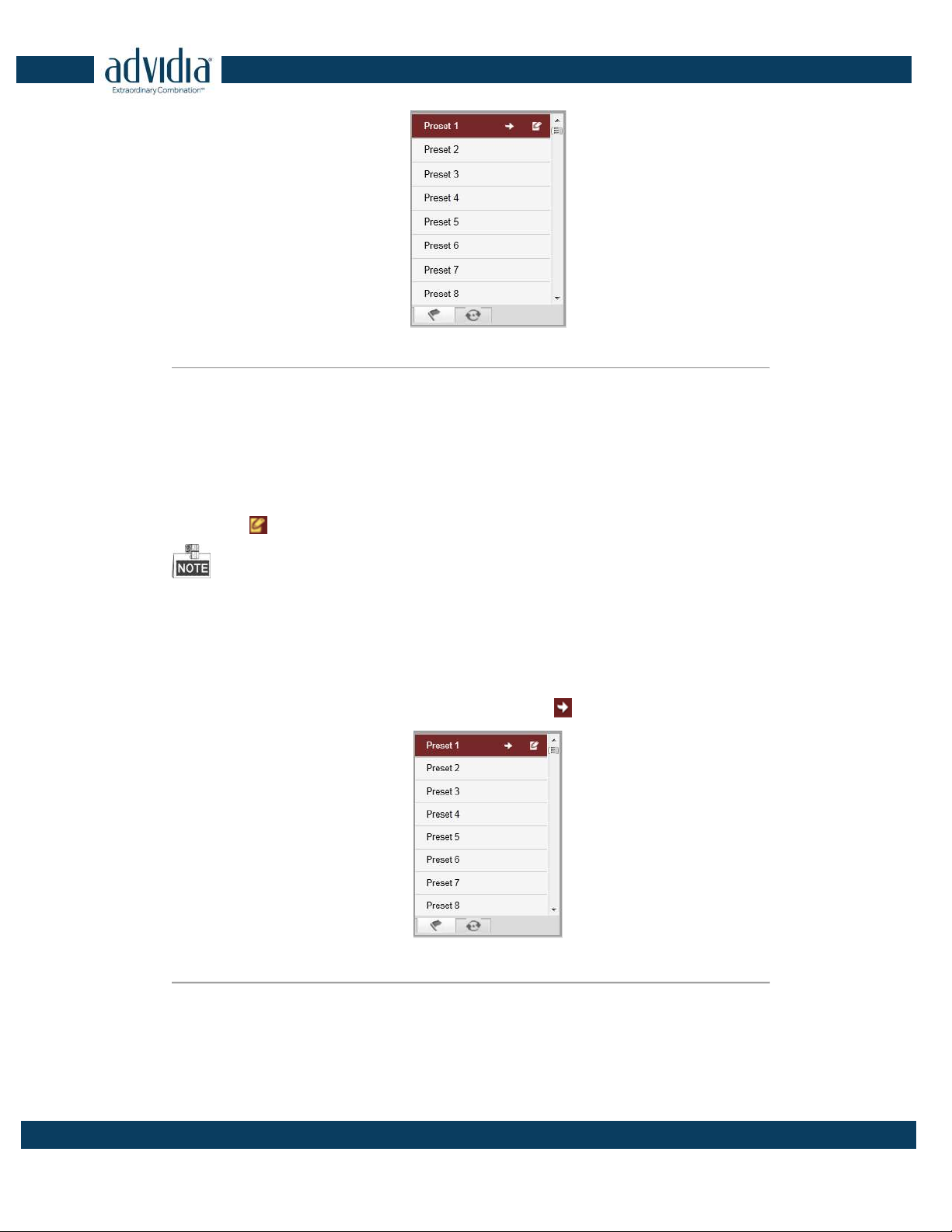
3.3.4 Setting/Calling a Preset
Setting a Preset:
1. In live view mode, click the
from the PTZ control area to enter the preset settings interface.
2. Select a preset number from the preset list.
VP-8-V2 and VP-16-V2 Series Encoder
·
User Manual
19
Figure 3. 6 Set a Preset
3. Use the PTZ control buttons to move the lens in the desired position. You can use any of the following
commands:
• Pan the camera to the right or left.
• Tilt the camera up or down.
• Zoom in or out.
• Refocus the lens.
4. Click the icon to finish the setting of current preset.
Up to 256 presets are configurable depending on the PTZ protocol applied.
Calling a Preset:
This feature enables the camera to point to a specified preset scene when an event takes place.
For the pre-defined preset, you can call it at any time to the desired preset scene.
In live view mode, select a predefined preset from the list and click the icon to call a preset.
Figure 3. 7
Call a Preset
Linking to Alarm:
The preset can also be used to link to the alarm input when there is an alarm event occurring.
This manual suits for next models
1
Table of contents
Other advidia Media Converter manuals

Popular Media Converter manuals by other brands

Advance acoustic
Advance acoustic RCE/100-2E-3 Operation manual

Sunstech
Sunstech DTB700PT user manual

Century
Century Clone Plus CROS2EU2CP user manual

Omnitron Systems Technology
Omnitron Systems Technology 8599R Series user manual

AAS
AAS HD-SD-HDMI-PRO user manual

Transition Networks
Transition Networks M/GE-SW-SFP-01-U Series user guide

Gefen
Gefen GTV-HIDEFS user manual

Accelerated
Accelerated Dial-to-IP 5301-DC Quick setup guide

Progressive Dynamics
Progressive Dynamics PD9200 SERIES owner's manual

Harman Kardon
Harman Kardon SC3 Operation manual

Cross Technologies
Cross Technologies 4117-14 instruction manual

Cypress
Cypress CP-261HS Operation manual


