advidia VP-16 Series User manual

VP-16 Series Encoder Server
USER’S MANUAL V1.0.1

1
Preventive and Cautionary Tips
Before connecting and operating your VP-16, please be advised of the following tips:
• Ensure unit is installed in a well-ventilated, dust-free environment.
• Keep all liquids away from the VP-16.
•Please check the power supply to avoid damage caused by voltage mismatch.
• Please make sure the VP-16 works in the allowed range of temperature and humidity.
•Please keep the device horizontal and avoid the installation under severe vibration environment.
•The dust board will cause a short circuit after damping; Please dedust regularly for the board, connector, chassis
fan etc. with brush.

2
TABLE OF CONTENTS
C H A P T E R
1
........................................................................................................................
4
Introduction ...............................................................................................................................
4
1.1 Description
...................................................................................................................... 5
1.2
Models
............................................................................................................................. 5
1.3 Features
........................................................................................................................... 5
C H A P T E R
2
........................................................................................................................
8
Structure
....................................................................................................................................
8
2.1 Front
Panel....................................................................................................................... 9
2.2 Rear
Panel........................................................................................................................ 9
2.3 HDD Installation
........................................................................................................... 10
2.4 Alarm
Connections
........................................................................................................ 11
2.4.1 Alarm Input Connections
....................................................................................... 11
2.4.2 Alarm Output
Connections
..................................................................................... 11
C H A P T E R
3
......................................................................................................................
13
Network Parameters
Configuration
.........................................................................................
13
3.1 Hyper Terminal Setup
................................................................................................... 14
3.2 Network Configuration by Hyper
Terminal.................................................................. 16
C H A P T E R
4
......................................................................................................................
18
Device
Configuration ..............................................................................................................
18
4.1 Install the Client
Software
............................................................................................. 19
4.1.1 System
Requirements............................................................................................. 19
4.1.2 Install
Software....................................................................................................... 19
4.1.3 Uninstall
Software
.................................................................................................. 20
4.2 Access to VP-16 by Client
Software......................................................................... 20
4.3 Access to Encoder by
IE................................................................................................ 24
4.4 PTZ
Control................................................................................................................... 27
C H A P T E R
5
......................................................................................................................
29
Remote Monitoring
.................................................................................................................
29

3
5.1 PPPoE
Settings
..................................................................................................................
30
5.2
Access by Router
...........................................................................................................
31
Appendix A
Specifications
......................................................................................................
33
Appendix B
FAQ.....................................................................................................................
35
Appendix C Glossary
..............................................................................................................
36

4
C H A PT E R 1
Introduction

5
1.1 Description
Developed on the basis of the latest encoding technology, VP-16 Series Audio/Video Encoder Server allows the
analog signal to be digitized and then stored in hard disk or transmitted via network, capable of encoding up to 16
channels of audio/video simultaneously at D1 resolution.
Adopting the latest embedded processor, VP-16 Series Audio/Video Encoder Server provides more powerful
capabilities in audio/video encoding; standard 1U chassis design maintains easy installation; adoption of newest
HDD storage technology ensures safe and reliable data storage; multiple network transmission protocols supported;
and code downloaded in FLASH ensures high stability and reliability of system performance.
1.2 Features
Encoding
Support H.264 encoding standard at PS and RTP customized encapsulation formats, of which RTP stream is used
for transmission via network and PS stream for recording;
Support encoding at 4CIF, DCIF, 2CIF, CIF and QCIF image resolutions;
Dual stream encoding;
Either compound streams encoding or video stream encoding selectable; audio and video synchronization during
compound streams encoding.
Recording
Multiple Recording Periods Configurable:
Up to 8 recording periods can be configured for each day, with different recording type selectable for each
recording period.
Cycle Recording:
Either cycle recording or non-cycle recording mode is configurable. In cycle recording mode, the earliest recording
will be overwritten when the HDD is full; and in non-cycle recording mode, the system will stop recording and
give alert when HDD is full.
Scheduled & Event Recording:
Each channel can be set with the scheduled recording and event recording separately, with separate resolution, bit
rate, frame rate and stream type configurable;
Multiple Record Triggering Modes:
Scheduled
recor
d
ing;
Motion
detection recording;
Alarm recording;
Motion detection/alarm recording;
Motion detection & alarm recording;
Pre-recording and Post-recording
Support pre-recording and post-recording, with the recording time configurable: 0-30sec for pre-recording and
5-600sec for post-recording;
Record Files Lock & Unlock
User may lock/unlock the record files, and the locked record files will not be overwritten in cycle-recording mode.
Individual Saving Time for Recording File
User is allowed to set different saving time for recording files from different channels. When reaching the defined
recording expiry time, the record files of the channel will be deleted automatically.

6
Read-only HDD Property Settings
The HDD can be set to read-only property so as to protect important data.
Network
One 10/100/1000Mbps self-adaptive UTP Ethernet interface;
Support TCP/IP, UDP, RTP and RTSP network protocols;
Capable of searching encoder through SADP software, as well as modifying the IP address, sub mask and
gateway of the encoder;
RTSP/RTP standard stream media protocol allows user to live view by Unicast;
Bi-directional voice talk and single-directional broadcasting;
Transmission via RS-232 and RS-485 transparent channels;
Access to Internet by PPPoE method, and support Peanut Hull, Dyndns, HIK protocol, etc.;
Set time by NTP;
Remote JPEG image capturing with user-defined image resolution and quality.
PTZ Control
Support Multiple PTZ Protocols
Different channels can be configured with protocol type, RS-485 address, baud rate, data bit, stop bit, even & odd
parity, stream control method, etc.; and remote configuration of presets, patrols and patterns.
Digital Zooming (with Speed Dome)
When connected with the speed dome, digital zooming can be realized by clicking on the image through client
software.
PTZ linkage
Relay input alarm can be responded to with PTZ linkage actions, e.g., callup of predefined presets, patrols or
patterns.
Alarm
Relay Alarm Input
Either NO mode or NC mode can be set;
Four different alarm arming periods are configurable;
Capabilities of triggering corresponding alarm handling methods, relay alarm output, buzzer alarm, upload to
control center, PTZ linkage, presets/patrols/patternscallup, etc.
Relay Alarm Output
Relay alarm output can be connected with alarm devices for alarm handling within arming period.
Exceptions
Exception Alarm Handling
Exception alarms include network disconnect alarm, IP address conflict alarm, illegal access alarm, etc.; multiple
alarm handling methods are supported, relay alarm output, buzzer alarm, upload to center, etc.
Exception Reboot
Software watchdog capability: for inspecting important tasks and system resources of device; in case of exceptions
detected, the device will be automatically rebooted.
Firmware watchdog: for inspecting the firmware of device; in case of exceptions in system task scheduling, the
device will be automatically rebooted.
UserAdministration
A maximum of 32 users can be created by the system, including 1 administrator and 31 users. The user name of the
administrator is admin, which cannot be modified, and the password can be modified by the administrator only; no
deletion of the administrator is allowed, and the administrator is authorized to set the operation permissions for
normal users.
Logs

7
The system logs can be classified into the operation logs, alarm logs, exception logs and information logs. User
may search and view all recorded system logs by date or type, as well as export the logs to the text format over
network.
SDK Interface
Available with SDK in Windows and Linux operating systems;
Available with application software source code for demo;
Available with development support and training service of the application system.

8
C H A PT E R 2
Structure

9
2.1 Front Panel
2.2 Rear Panel
VP-16
Rear
Panel
Interface Connections
1 VIDEO/AUDIO IN BNC connectors for video/audio input
2 LOOP OUT Video loop output connector (optional) for connection to monitor
3 LINE IN Voice talk input interface for connection to active audio input device,
microphone, etc.
4 AUDIO OUT Voice talk output interface for connection to audio output device, e.g.,
loudspeaker, etc.
5 RS-232 Serial interface for configuration of device’s parameters or used as
transparent channel
6 POWER Power on/off
7 LAN 10/100/1000Mbps self-adaptive UTP Ethernet interface
8 RESET Restore the factory default settings by holding the RESET button for 15
seconds after power is on.
9 RS-485 RS-485 serial interface for connection to pan/tilt unit, speed dome, etc.
10 ALARM IN Relay alarm input
11 ALARM OUT Relay alarm output
12 AC220V 220VAC power supply
13 GND Ground
10
2.3 Alarm Connections
2.3.1 Alarm Input Connections
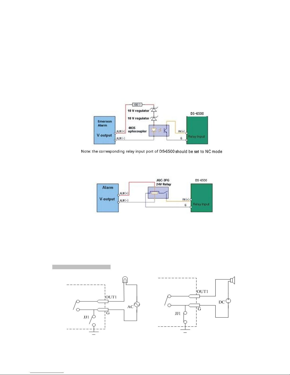
VP-16 supports the open/close relay input as the alarm input mode. For the alarm input signal not in open/close
relay signal mode, please follow the connections shown below:
Alarm input connections for Emerson Alarm:
Alarm input connections for Normal Alarm:
2.3.2 Alarm Output Connections
VP-16 supports the open/close relay input as the alarm output mode. The alarm input can be selected to NO or NC.
Different alarm output connection methods are applied to the AC or DC load, please refer to the following
diagram:
Alarm
output
connections
diagram:

11
Please note the different connections of JJl shown
above.
For DC load, JJl can be safely used both in NC and NO methods, and it is
recommended
that they be used within the
limit
of
12V/1A.
For external AC
input
,
JJl must be open. The
motherboard
provides two
jumper
s
,
each
corresponding
to
one alarm output. Both jumpers are factory set to be
connected.

12
C H A PT E R 3
Network Parameters Configuration

13
Description:
This chapter covers the network parameters configuration of VP-16.
The VP-16 factory default user name is “admin,”password is “12345.”
The VP-16 factory default IP address is 192.0.0.64.
The network parameters need to be set up before the decoding channel configuration. The network parameters are
used to connect with the software, which is applied to set the decoding channels. The network parameters
include IP address, subnet mask, gateway and port.
3.1 Hyper Terminal Setup
The common method is to connect decoder and PC with serial line, run Hyper Terminal and modify parameters
with serial command. Please connect the RS-232 port of decoder directly to the COM port of PC, power on the
decoder and PC and follow the steps:
Step1: Enter Hyper Terminal.
Click “Start”->
“Programs”->” Accessories”-> “Communications”-> “Hyper
Terminal” in Windows system, and the
dialogue box below will appear as in Figure 3.1.1.
Step2: Name the connection and define the icon.
Input a name (e.g. VI), select an icon, and press “OK” to enter “Connect To”dialogue box.
Step3: Select the communication port.
Select “COM1” in “Connect To”interface (Please select the COM port according to the reality, in case PC has
more than 1 COM.). Press “OK” to enter “Properties” dialogue box.

14
Figure 3.1.2
Step4: Serial port setup.
Set port parameters in “COM1 Properties” dialogue box as follow: (Fig 3.1.3)
Figure 3.1.3
The parameters should be:
Bits per second: 115200
Data bits: 8
Parity: None
Stop bits: 1
Flow control: None
15
Press “Apply”and “OK” after the setup.
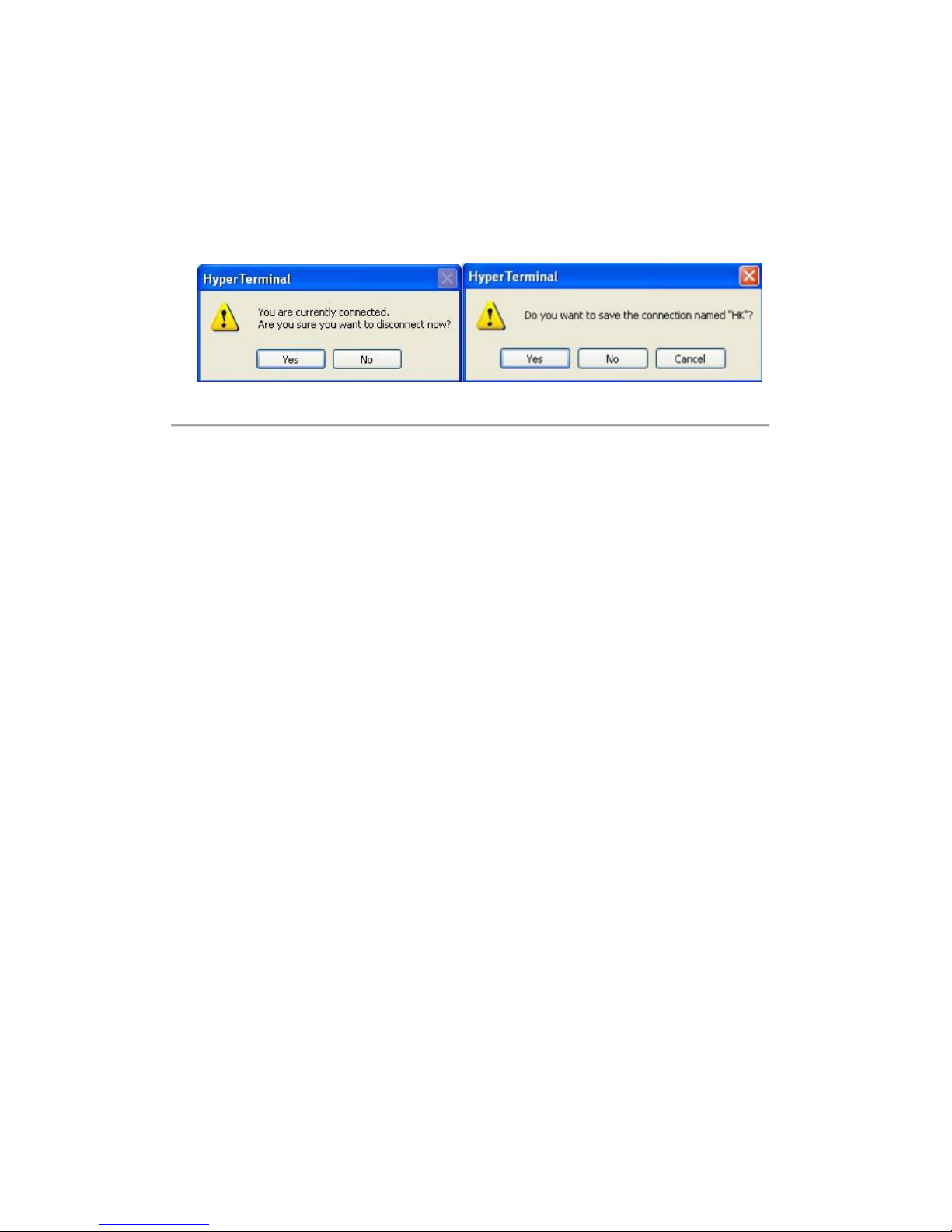
Press “Enter”under Hyper Terminal interface. When “[root@dvrVP-16 /]#”appears, the connection is established.
According to the tips, disconnect and save “VI” for the next time. After saving, there will be a new “Hyper
Terminal” item established in the program group “Start”->
“Accessories”-> “Communications”-> “Hyper
Terminal.”
“Connection” names of all Hyper Terminal are included. You can see an icon named as “VI” here.
Figure 3.1.5
3.2 Network Configuration by Hyper Terminal
Enter Hyper Terminal
Click “Start”-> “Programs”-> “Accessories”-> “Communications”-> “Hyper Terminal”-> “HK”, then the Hyper
Terminal interface will appear as figure below.
Type “Enter”and the prompt “[root@dvrVP-16 /]#” will appear, which means connection between RS232 interface
of PC and RS232 interface of VP-16 is established successfully by Hyper Terminal.
The following operation commands are to accomplish the parameters setup in the prompt

16
Commands Description:
Commands
Utilities
helpm
Console help command is used to print common commands, show as Figure 3.2.
getIp
Show the current IP address of decoder. Command format: getIp + “Enter”.
setIp
Set decoder IP address.
Command format: setIp IP: mask, e.g. setIp 192..168.1.11:255.255.255.0
getPort
Get data port of the current video server. Command format: getPort+ “Enter”
setPort
Get data port of the video server. Default port: 8000, command format: getPort+Port No.,
e.g., setPort 9000.
getGateway
Show current decoder gateway address. Command format: getGateway+ “Enter”.
setGateway
Setup decoder gateway.
Command format: setGateway Gateway, e.g. setGateway 192.168.1.1
Note: These are only common commands. The other commands please consult our technical engineers.

17
C H A P T E R 4
Device Configuration

18
Instructions:
The VP-16 video server can be accessed either by client software or by IE browser.
Before access, user needs to configure the network settings of VP-16 according to Chapter 3.
Connect the VP-16 to the LAN, and prepare a PC connected to the same LAN with VP-16.
The factory default username of VP-16 is “admin”and the password is “12345.”
The factory default IP address of VP-16 is 192.0.0.64 and the port is 8000.
4.1 Install the Client Software
4.1.1 System Requirements
Open the accessories box to take out the disk, which provides camera finder software supplied by our corporation.
The following section describes the configuration of encoder through the software.
Operating System: Microsoft Windows 2000 or higher
CPU: Intel Pentium IV 2.4 GHz or higher
RAM: 1G or higher
Display: 1024×768 resolution or higher
4.1.2 Install Software
Double click icon and you will see the wizard shown as below:
Figure 4.1.2.1
Click “Next” to continue, and input the user information, software installed location according to the hints.
An SADP installation wizard will pop up; click “Next” to start to install WinPcap. If it is already installed, the
installation can be cancelled.

19
Figure 4.1.2.2
Note: SADP is used as the on-line device finder; this function is unavailable if the WinPcap is not installed.
4.2 Access to Encoder by IE
Open IE browser, input the IP address of VP-16 (e.g., 192.0.0.64) and then click “Enter.”The system will remind
you to install the ActiveX control. Click and install the ActiveX control.
The system will then display the login interface as shown in Figure 4.3.1:
Table of contents
Other advidia Media Converter manuals


