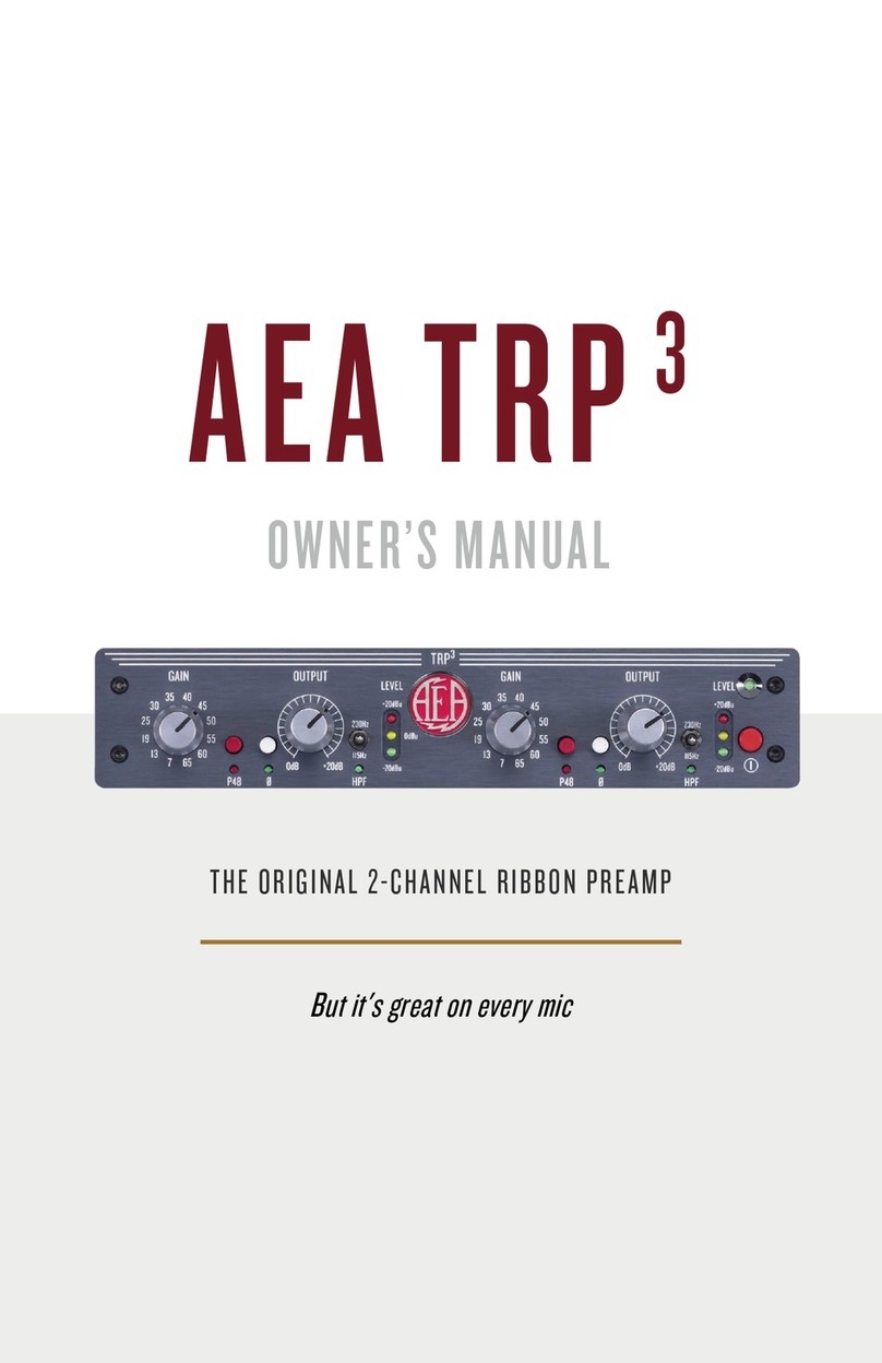
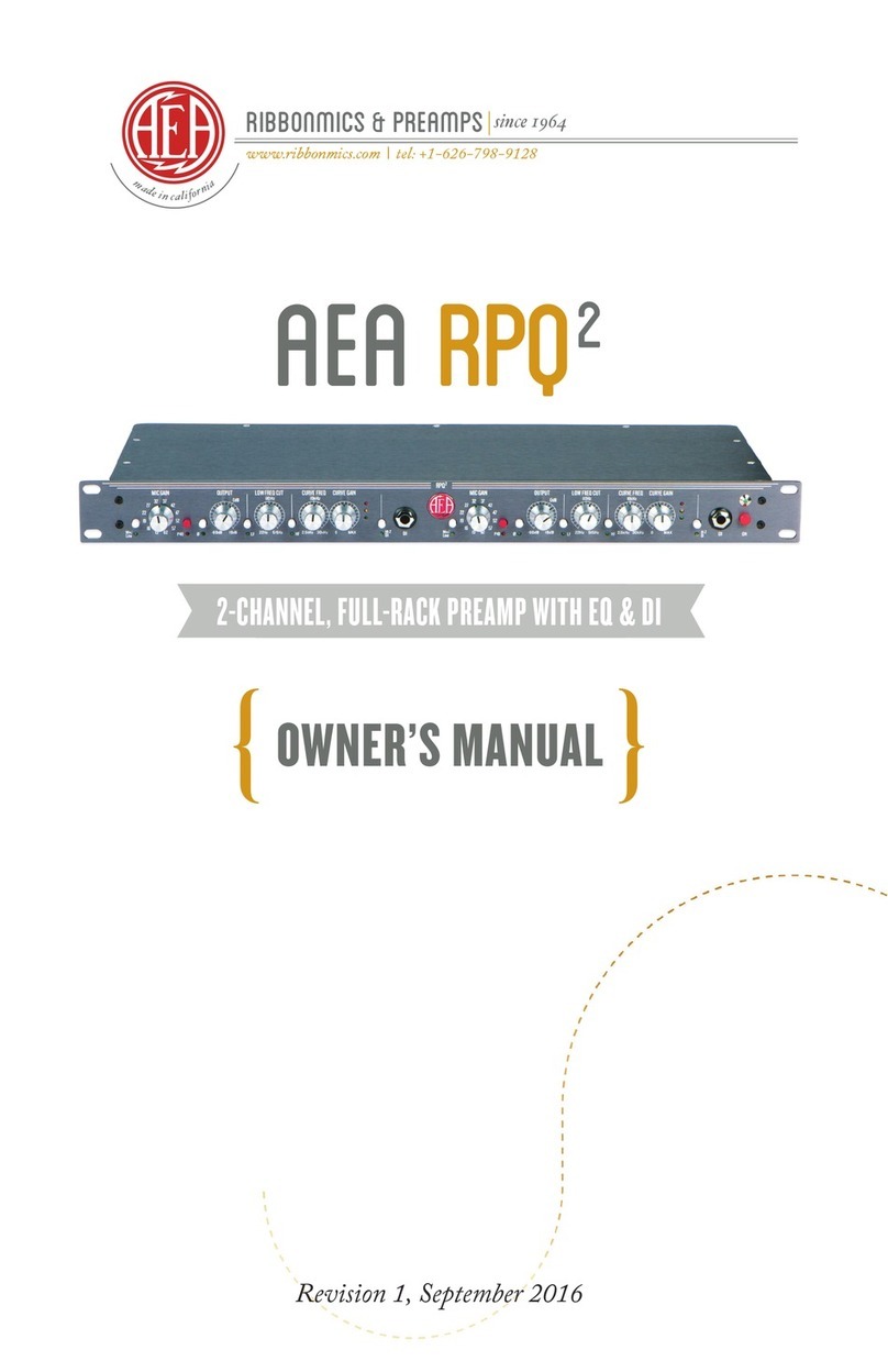
AEA RPQ3 User manual

2-CHANNEL RIBBON PREAMP WITH EQ
AEA RPQ3
OWNER’S MANUAL
But it's great on every mic

WELCOME
Congratulations on your purchase of the AEA RPQ3 microphone
preamplifier, AEA’s third iteration of our low noise, ultra-high gain
and impedance architecture. Inspired by its older siblings the RPQ
and the RPQ2, the RPQ3 improves upon a trusted blueprint using
the most up-to-date technology available. At AEA, we put the
same thought and care into our preamps as we put into the
development of our microphones: sonic quality comes first.
Since 2006, AEA's preamps have surpassed the limitations of 20th
century electronics, allowing you to fully appreciate the sonic
complexities of your microphone. The RPQ3 leans on the side of
neutral but is unlike other "clean" preamps because of its rich and
musical tonality. It offers up to 85 dB of effortless gain for any
microphone, as well as an expanded EQ section that allows you to
finely tune your signal.
Your RPQ3 is 100 percent handcrafted in Pasadena, California.
AEA is a family-owned company with a small crew of skilled
technicians, many of whom are musicians themselves. Proudly
independent, we still manufacture all our ribbon microphones and
preamps by hand, in-house, from locally sourced parts. We hope
the RPQ3 helps capture many magical musical performances. Read
this manual thoroughly to make sure you get the best sound and
longevity from your new preamp. We invite you to become part of
the AEA community by sharing your experiences with the RPQ3 via
email, phone, or our social media channels.
The AEA team
2

CONTENTS
WELCOME
INTRODUCTION
WARRANTY
SUPPORT
GENERAL GUIDELINES
SETTING THE GAIN
SPECIFICATIONS
2
4
4
4
5
12
15
3

INTRODUCTION
Based on the circuit design of our celebrated RPQ2, the RPQ3
features a powerful combination of ultra-low noise, low-distortion
op-amps, ultra-high 68 kΩ input impedance, and 85 dB of clean
gain, all packaged in a durable full-rack chassis. The RPQ3 also
includes an expanded EQ section with boost and cut controls for
both low and high end as well as a new low-end frequency sweep
to identify and eliminate rumbles and resonances. The RPQ3 was
designed to work great on passive ribbon microphones, however,
when a preamp works well with a passive ribbon microphone, it
will excel on every microphone. At once open, transparent, and
musical, the RPQ3 is a versatile tool for the front end of any signal
path. As with all AEA electronics, the circuit in the RPQ3 was
designed by Fred Forssell.
SUPPORT
If you should encounter any problems with your preamp or have
questions regarding using the RPQ3in specific applications,
please contact our customer support team at
[email protected] for the quickest response.
To contact us by phone, please call 626-798-9128 from 9:00 a.m.-
5:00 p.m. PST Monday-Friday. AEA's repair center is located at
1029 N. Allen Ave, Pasadena, CA 91104, U.S.A.
WARRANTY
Your RPQ3 comes with a one-year
limited warranty on parts and labor*.
Registering your preamp within 90 days
will extend the warranty to three (3) years.
Scan the QR code or visit our website to
register.
*AEA is not responsible for shipping costs
4

GENERAL GUIDELINES
To maintain the best performance from your new AEA RPQ3
preamp, take note of these two requirements:
1) Never place preamp in close proximity to electromagnetic fields
or hot surfaces. Electromagnetic fields created by power
transformers, motors, or RF transmitters can potentially damage or
interfere with the preamp functionality. Make sure to keep your
preamp away from these sources in addition to hot surfaces.
2) Before turning on the power, all connections to the preamp
should be made and the Gain and Output Level controls set at
their minimum settings. Be sure to examine your signal chain
before powering up the preamp to ensure sudden loud noises are
not emitted which could damage your system or hearing.
INPUT IMPEDANCE
Passive ribbon microphones and numerous moving coil dynamic
microphones are very particular about how they interact with
preamps and their respective impedances play an important part
in this. Since passive ribbon microphones and some dynamic
microphones generally have a very high impedance, they are
sensitive to what is referred to as “loading.” The lower impedance
a mic must drive, the harder the mic has to work. If the input
impedance of a preamp is too close to the impedance of the
microphone, it may exhibit increased distortion, decreased
headroom, poor transient response, and less overall frequency
response. There are no negative consequences to using high input
impedance preamps.
The ultra-high gain JFET circuit has two input impedances: 11.3 kΩ
with phantom power "ON" and 68 kΩ with phantom power "OFF."
The 68 kΩ brings out the best in passive ribbons and tube mics,
and also provides a unique balanced input for vintage, high-
impedance dynamic mics. This versatility ensures the highest
sensitivity, bandwidth, transient response, and clarity possible for a
wide variety of microphones.
5

6
FRONT PANEL GUIDE
1 - Insert switch:
OUT is Mic Input mode; IN is Insert mode which sends the
preamp signal out the Line Out ¼” jack and switches the pre-
eq input to the Line Input ¼” jack on the rear of the unit. The
LED below the switch will indicate when the insert is engaged.
2 - Mic Gain rotary switch:
This twelve-position switch selects from +7 dB to +65 dB of
preamplifier gain.
3 - Phantom Power (P48) switch:
OUT is off; IN applies full-spec P48 phantom power to the
input. The red LED below the switch will indicate when P48
phantom power is engaged.
4 - Polarity Invert switch:
OUT is normal; IN is inverted.
5 - Output Level control:
This continuously variable control provides up to +20 dB
additional output gain following the optional CurveShaper™
EQ circuitry. Fully counter-clockwise -- 0 dB -- indicates unity.
6 - EQ IN switch:
OUT bypasses the EQ circuitry; IN engages the EQ circuitry.
Note, the LF (ref. #8) and/or HF (ref. #11) must also be engaged
to use the EQ. The EQ IN switch allows for easy A/Bing with
and without EQ.
⬆ ⬆ ⬆ ⬆ ⬆ ⬆⬆⬆ ⬆ ⬆ ⬆ ⬆ ⬆ ⬆⬆
1 2 3 4 5 6 7 8 9 10 11 12 13 14 15

7
7 - GAIN RANGE +/- 10 dB switch:
OUT is bypass, IN changes the +/-20 dB gain ranges on the
LF GAIN (ref. #9) and the HF GAIN (ref. #12) to +/-10 dB,
which allows for more accuracy in dialing in EQ
8 - Low Frequency (LF) In switch:
OUT is bypass; IN inserts the 20 dB boost/cut shelving filter and
variable frequency sweep. The green LED below switch will
indicate when LF EQ is engaged.
9 - Low Frequency Curve Gain control:
This continuously variable control adjusts the LF gain from -20
dB to +20 dB; the slope of the CurveShaper™ EQ varies as
Curve Frequency and Curve Gain settings interact.
10 - Low Frequency Filter control:
This continuously variable control adjusts the -3 dB break-
frequency (as measured at full cut; -20 dB on the LF Gain) of the
filter from 40 Hz to 675 Hz; maximum LF reduction is -20 dB.
11 - High Frequency (HF) In switch:
OUT is bypass; IN inserts the HF EQ circuitry. The green LED
below switch will indicate when HF EQ is engaged.
12 - High Frequency Curve Gain control:
This continuously variable control adjusts the HF gain from
-20 dB to +20 dB; the slope of the CurveShaper™ EQ varies as
Curve Frequency and Curve Gain settings interact.
13 - Curve Frequency control:
This continuously variable control adjusts the +3 dB break-
frequency (as measured at full boost; +20 dB on the HF Gain)
from 2 kHz to 28 kHz.
14 - Audio Signal Level indicators:
The green LED snaps on at -20 dBu to indicate the presence of
signal. The yellow LED snaps on at 0 dBu. The red LED snaps
on at +20 dBu to warn of approaching signal overload.
15 - Power Switch:
OUT is off; IN powers on unit.
Green LED above the switch will indicate that the unit is on.


10
REAR PANEL GUIDE
A - Balanced Output - XLR:
Female three-pin XLR: pin-1 is ground, pin-2 is high (+), and
pin-3 is low (-).
B - Balanced 1/4” TRS Line In:
Line Input mode connector. Bypasses the mic preamp gain
stage to accommodate line-level signals. Depress the
INSERT switch (ref. #1) to utilize this Line Input mode input.
C - Balanced 1/4” TRS Line Out:
Direct output of preamp gain stage before EQ and Output
Level control. Note: this output always outputs a signal,
whether or not the INSERT is engaged. This allows for an
optional dry signal recording as well.
D - Balanced Input - XLR:
Mic Input mode connector. Male three-pin XLR: pin-1 is ground,
pin-2 is high (+), and pin-3 is low (-).
Note: Balanced 1/4" TRS is tip high, ring low, sleeve ground
INSERT/LINE INPUT MODE
Line Input mode bypasses the mic preamp stage to accommodate
line-level signals. Depressing the Insert switch bypasses the first
gain stage and routes the signal from the Line Input connector
straight to the optional CurveShaper™ circuitry and Output Level
control (ref. #5). The illuminated green LED below the Insert switch
indicates when the insert is active. Plug line level signal sources
into the Line In connector (ref. B) located on the back panel.
⬆ ⬆ ⬆ ⬆
A B C D

11
Insert mode allows you to insert compressors or other effects
between the preamp and CurveShaper™ EQ section. While the
Insert switch is depressed, the preamp section of the RPQ3 is still
active; however, it is independent of the Output Level control and
CurveShaper™ EQ circuitry. To use the inserts with an effect, plug a
mic into the XLR Input (ref. D) and take the 1/4” balanced Line Out
(ref. C) into another piece of hardware such as a compressor.
Connect the output of the compressor and plug it directly into the
1/4” Line In (ref. B). The standard XLR Output (ref. A) is the post-EQ
output.
OUTPUT CONNECTIONS
In Mic mode (meaning the insert is not engaged), the XLR Input
routes through the preamp gain stage, optional CurveShaper™
EQ, and Output Level control to the XLR output. You may also use
the 1/4” Line Out (ref. C) simultaneously as an auxiliary output of
the preamp gain stage. Signals running through the XLR input (ref.
D) in Insert mode will pass through the preamp gain (ref. #2) stage
and 1/4” Line Out. In Insert mode, sources plugged into the line
connector will bypass the preamp gain stage and route through the
optional CurveShaper™ EQ and Output Level control to the XLR
Output.
The output of the RPQ3 emulates a transformer-coupled output
and can be used as either a balanced or unbalanced signal
(depending on how your cable/system is configured). When
balanced, the maximum output level is +27 dBu; when unbalanced,
the maximum level is +21 dBu. (These are as measured into a 600 Ω
load; the recommended load is > 10 kΩ; 0 dBu = 0.7746 V rms.)
When unbalancing the XLR Output, pin-3 must be tied to ground at
the receiving end (i.e. the input of the following device). Do not tie
pin-3 to ground directly at the output of the RPQ3. We recommend
testing your cables regularly to be sure that they are in proper
working order.

12
SETTING THE GAIN
The RPQ3’s minimalist JFET circuit design delivers up to 85 dB of
clean, quiet gain. With extended bandwidth from below 10 Hz to
beyond 200 kHz, it delivers effortless dynamic range and transient
response that complements all microphones.
As with any piece of audio equipment, setting and maintaining
proper signal levels is critical to obtaining optimum performance. If
the level is set too low, noise performance is sacrificed; if the level is
too high, there’s a risk of overload distortion.
Setting the AEA RPQ3 gain begins by setting the first stage GAIN
and second stage OUTPUT knobs fully counterclockwise. The first
stage GAIN control has 12 precision steps from +7 dB to +65 dB.
The second stage OUTPUT potentiometer knob when all the way
down (counterclockwise) adds no gain, and all the way up adds +20
dB. The three LEDs: green, yellow and red (ref. #14) snap on at -20,
0, and +20 dBu to indicate signal activity.
First Stage GAIN Control Adjustment
Connect the microphone and then, if needed, turn on phantom
power. Have the performer(s) play a louder section and click up the
GAIN (ref. #2) until the yellow LED usually lights and the red LED
rarely lights.
Second Stage OUTPUT Gain Trim
The OUTPUT Control (ref. #4) potentiometer adjusts gain from 0 dB
(unity gain) at the bottom to +20 dB gain when fully turned up. Like
the 12-step GAIN control, the 0 dB and +20 dB OUTPUT positions
are accurate and repeatable. Approximate OUTPUT gain at 9, 12,
and 3 o’clock are +3 dB, +7 dB, and +17 dB. The red LED lights 7 dB
before clipping with a balanced load, so listen carefully to see how it
sounds when the red LED lights up more often.
We actively encourage users to visit AEAribbonmics.com to
access our comprehensive collection of in-depth articles and
tutorials featuring AEA products,along with a library of
audio and video demonstrations of the products in action.

13

14
RPQ3Single Line Drawing

15
SPECIFICATIONS
Max Gain at 1kHz:
EIN (Max Gain 22 Hz to 22 kHz):
Frequency Response:
THD+N:
XLR Output Maximum Level:
Input Impedance:
Input Impedance (P48 Engaged):
Output Impedance:
Max Input Signal Level
Mic Gain Control:
Output Trim:
EQ Circuitry:
-
-
-
Input and Output XLR Polarity:
LED Signal Level Indicators:
Dimensions:
Weight:
85 dB
-130 dBu (typical), 40 Ω source unweighted
-128 dBu (typical), 150 Ω source unweighted
30 dB gain: (-0.6 dB 10 Hz, -3 dB 160 kHz)
85 dB gain: (-3 dB 10 Hz and 160 kHz)
0.0018% (1 kHz, 22 Hz-22 kHz @30 dB Gain
+4 dBu output)
+27 dBu into 600 Ω load
68 kΩ
11.3 kΩ
50 Ω
+20 dBu (minimum gain)
12-position switch from +7 dB to +65 dB
Continuously variable from 0 dB to +20 dB
First order shelving response
20 dB max boost/cut high range, 10 dB max boost/
cut low range
Low frequency sweep continuously variable
40 Hz to 675 Hz
High frequency sweep continuously variable
2 kHz to 28 kHz
Pin 2 high
Green LED ≅ -20 dBu;
Yellow LED = 0 dBu;
Red LED ≅ +20 dBu (clipping +27 dBu)
1U, Full-rack measured with knobs and switches:
19” w, 9” d, 1.75” h (48.25 cm x 23.85 cm x 4.55 cm)
4lb 6oz (~2 kg)
In compliance with the following requirements: RoHS2
Directive: 2011/65/EU

Table of contents
Other AEA Amplifier manuals
