2 J L A U D IO M12IB6
A
C
B
E
D
INS T AL L AT ION P R OC E DUR E
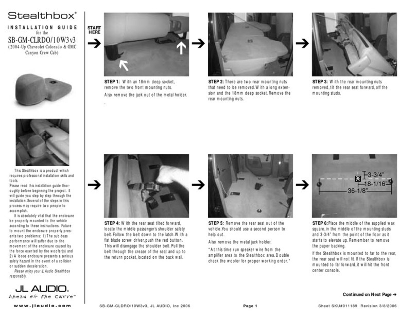
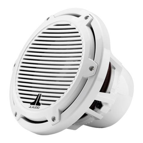
The diagram above showsthe typical
installation procedure into a fiberglasspanelusing
the supplied hardware (Classic Grille Modelshown.
Installation isthe same forSportGrille Models).
Alwaysfollow propersafety procedureswhen
working on a vessel.Use eye-protection atalltimes
and a dustmask and gloveswhen cutting.
1)Choose a flatmounting surface thathas
sufficient
depth and airspace behind itto accept
the subwoofer.
2)Cuta 12.0625-inch (306 mm)diameterhole.
3)Run the speakercable to the mounting location.
4)Place the wooferin the hole and mark the screw
hole locationsusing a sharp,pointed tool.
5)Remove the wooferand drilla pilothole
(see charton nextpage)in each ofthe screw
locations. Itisalso advisable to use a hand-driven
countersink toolon each hole to furtherinhibit
gel-coatcracking offiberglasspanels.
6)Connectthe speakerwiresand place the woofer,
with itsgrille in place,into the opening (forSport
Grille models,pay attention to where the logo
badge willadded.
7)While holding the speakerfirmly in itsmounting
location,evenly snug the mounting screwsin a
criss-crosspattern,then hand tighten in a criss-
crosspattern.
Non-standard installationsmay require different
hardware.Always use marine-grade,stainless-steel
fasteners to ensure a secure,reliable installation.
We recommend the use ofthis speakerin a bi-amplified system using high-quality satellite speakers and amplifiers.
We do notrecommend the use ofthis subwoofer with a passive crossover (coil),as this type ofdevice willadversely
affectperformance.
A ll sp e c ific a tio n s a re su b je c t to c h a n g e w ith o u t n o tic e .
P HY S IC AL S P E C IF IC AT IONS
INC L UDE D P AR T S
•One PolymerSubwooferGrille
•Six #10 x 1 5/8-inch (41 mm)pan-head
stainless-steelscrews
•Six #10 stainless-steelwashers
•Logo Badges(Sport-Grille ModelsOnly)
One PairBlack (White & Titanium/Black Models)
One PairRed (White & Titanium/Black Models)
One PairWhite (White Models Only)
One PairTitanium (Titanium/Black Models Only)
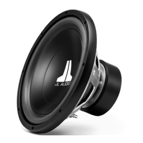
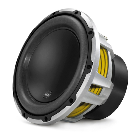
S u b wo o fe r P h y s ic a l S p e c if ic a t io n s
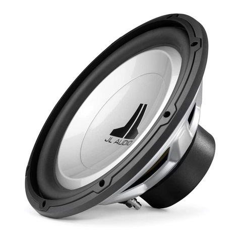
NominalDiameter: 12 in./300 mm
OverallDiameter(A): 14 in./ 356 mm
Mounting Hole Diameter(B): 12.0625 in./306 mm
BoltHole Circle (C): 12.813 in./325 mm
MotorOvermold OuterDiameter(D): 8.84 in./225 mm
Mounting Depth (E): 8.05 in./ 204 mm
NetWeight: 23.8 lbs./10.80 Kg
DriverDisplacement: 0.153 ft3/ 4.33 litres
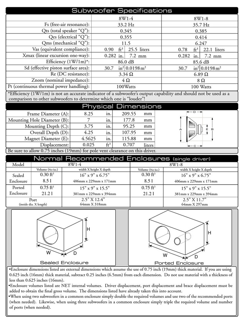
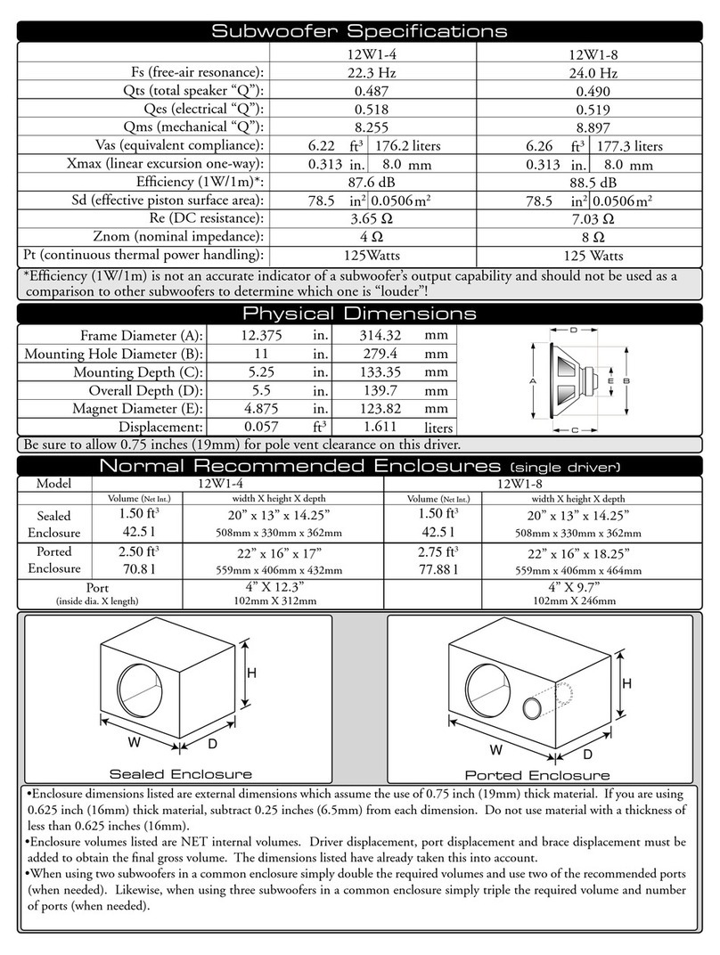
S u b wo o fe r P a r a me t e r s M1 2 IB 6
Free AirResonance (Fs): 35.34 Hz
Electrical“Q”(Qes): 0.856
Mechanical“Q”(Qms): 10.389
TotalSpeaker“Q”(Qts): 0.791
EquivalentCompliance (Vas): 1.99 ft
3/56.35 litres
One-way,LinearExcursion (Xmax)*: 0.73 in./18.5 mm
Efficiency (1W/1m)**: 86.7 dB SPL
Effective Piston Area (Sd): 80.54 in²/0.0520 m²
DC Resistance (Re): 3.543 ohm
NominalImpedance: 4 ohm
Infinite Baffle Use: Yes
Enclosure Use: Yes (Sealed and Ported)
PowerHandling (continuous): 600W
* X ma x s p e c ific a tio n s a re d e riv e d v ia o n e -wa y v o ic e c o il o v e rh a n g me th o d with n o c o rr e c tio n fa c to r s a p p lie d .
* * E ffic ie n c y (1 W/1 m) is n o t a n a c c u r a te in d ic a to r o f a s u b wo o fe r ’s o u tp u t c a p a b ilit y a n d s h o u ld n o t b e u s e d
a s a c o mp a r is o n to o t h e r s u b wo o fe r s t o d e te r min e wh ic h o n e is “ lo u d e r ” !

