AEC AD Series Specification sheet
Operation and Installation Manual
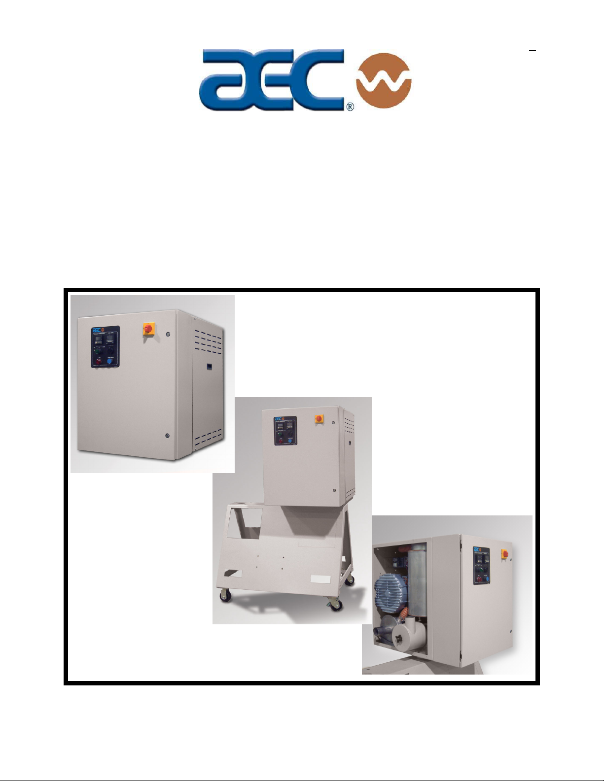
AD Series
Dehumidifying Dryers
Important! Read Carefully Before Attempting to Install or Operate Equipment
Part No. A0555768 Revision A Bulletin No. WH1-645.1
$3000

Page 2 AD Series Dehumidifying Dryers
Write down your dehumidifying ________________ ________________
dryer serial numbers ________________ ________________
here for future reference ________________ ________________
________________ ________________
Performance figures stated in this manual are based on a standard atmosphere of 59°F
(15°C) at 29.92” Hg (1,014 millibars) at sea level, using 60 hz power. Altitude is an
important consideration when specifying dehumidifying dryers. AEC can advise you on
proper selection and sizing of systems for your operating environment.
AEC is committed to a continuing program of product improvement.
Specifications, appearance, and dimensions described in this manual
are subject to change without notice.
© Copyright AEC, Inc. 2003
All rights reserved. Effective 6/10/2003
Part No. A0555768 Revision ABulletin No. WH1-645.1

AD Series Dehumidifying Dryers Page 3
Table of Contents
1 General Information ............................................................9
1-1 Models Covered .......................................................................................................... 9
1-2 Equipment Function .................................................................................................... 9
1-3 Necessary Documents ................................................................................................ 9
1-4 Standard Features..................................................................................................... 10
1-5 Options......................................................................................................................10
1-6 The Drying System.................................................................................................... 11
1-7 What is Desiccant?.................................................................................................... 13
1-8 The Process/Regeneration Cycle.............................................................................. 13
1-9 Specifying a Drying System ...................................................................................... 14
2 Safety..................................................................................15
2-1 Work Rules................................................................................................................15
2-2 Tools and Equipment Needed................................................................................... 15
2-3 Mechanical Installation .............................................................................................. 15
2-4 Safety Considerations ............................................................................................... 16
2-5 General Responsibility .............................................................................................. 17
2-6 Operator Responsibility ............................................................................................. 17
2-7 Maintenance Responsibility....................................................................................... 19
2-8 Safety ........................................................................................................................ 20
3 Shipping Information ........................................................23
3-1 Unpacking and Inspection ......................................................................................... 23
3-2 In the Event of Shipping Damages............................................................................ 23
3-3 If the Shipment is Not Complete................................................................................ 24
3-4 If the Shipment is Not Correct ................................................................................... 24
3-5 Returns......................................................................................................................24
4 Installation .........................................................................25
4-1 Work Rules................................................................................................................ 25
4-2 Rigging and Placing the Dryer................................................................................... 25
4-3 Making Electrical Connections .................................................................................. 28
4-4 Checking for Proper Blower Rotation ........................................................................ 28
4-5 Making Dryer/Drying Hopper Process Air Connections............................................. 29
4-6 Drying Hopper Air Trap Considerations .................................................................... 29
4-7 Installing the Optional Aftercooler ............................................................................. 30

Page 4 AD Series Dehumidifying Dryers
Table of Contents
5 Controls..............................................................................31
5-1 Identifying Control Panel Indicator Lights and Switches for Standard Controller ...... 31
5-2 Process Air Temperature Controller.......................................................................... 33
5-3 Identifying Process Air Temperature Controller LED Indicators ................................ 34
5-4 Identifying Temperature Controller Keys................................................................... 35
5-5 Setting the Process Air Temperature ........................................................................ 35
5-6 Restoring the E5CN Temperature Controller to Factory Setup ................................. 36
5-7 Process Air Dew Point Display.................................................................................. 38
5-8 Setting the High Dew Point Alarm ............................................................................. 39
5-9 Restoring the E5CK Dew Point Meter to Factory Setup............................................ 39
5-10 Redundant Safety Controller Display ........................................................................ 40
5-11 Setting the Redundant Safety Controller................................................................... 40
5-12 Restoring the WATLOW Redundant Safety Controller to Factory Setup .................. 40
6 Control Operation..............................................................43
6-1 Controller Operation .................................................................................................. 43
(Without Optional Alarm Horn & Reset Button) ...................................................................... 43
6-2 Controller Operation .................................................................................................. 46
(With Optional Alarm Horn & Reset Button) ........................................................................... 46
6-3 Alarm Display Messages........................................................................................... 49
7 Startup, Shutdown, and Operation .................................. 51
7-1 Pre-Startup Checks ................................................................................................... 51
7-2 Starting Up the Dryer................................................................................................. 51
7-3 Shutting Down the Dryer ........................................................................................... 52
8 Maintenance.......................................................................53
8-1 Work Rules................................................................................................................ 53
8-2 Servicing Process Air Filters ..................................................................................... 53
8-3 Servicing the Dew Point Monitor ............................................................................... 55
8-4 Symptoms of Worn Desiccant ................................................................................... 55
8-5 Replacing Worn Desiccant ........................................................................................ 56
8-6 Replacing the Process Heater................................................................................... 58
8-7 Replacing/Cleaning the Regeneration Heater/Cooling Coils..................................... 60
9 Troubleshooting ................................................................63
10 Dryer Options ....................................................................67
11 Spare Parts ........................................................................68
11-1 Spare Parts List ............................................................................................................. 68
12 Technical Assistance........................................................70
12-1 Contact Information for Technical Assistance............................................................... 70
12-2 Returned Material Policy ............................................................................................... 71
12-3 Warranty ....................................................................................................................... 72
13 Safety Tag Information .....................................................74
13-1 AD Dryer Safety Tags ................................................................................................... 74
13-2 Dryer Identification (Serial Number) Tag...................................................................... 75

AD Series Dehumidifying Dryers Page 5
Safety Considerations
AEC AD Series dehumidifying dryers are designed to provide safe
and reliable operation when installed and operated within design
specifications, following national and local safety codes.
To avoid possible personnel injury or equipment damage when
installing, operating, or maintaining this equipment, use good
judgment and follow these safe practices:
;Follow all SAFETY CODES.
;Wear SAFETY GLASSES and WORK GLOVES.
;Disconnect and/or lock out power before servicing or
maintaining the dryer.
;Use care when LOADING, UNLOADING, RIGGING, or
MOVING this equipment.
;Operate this equipment within design specifications.
;OPEN, TAG, and LOCK ALL DISCONNECTS before
working on this equipment. It is a good idea to remove the
fuses and carry them with you
;Make sure the dryer and components are properly
GROUNDED before switching on power.
;Do not jump or bypass any electrical safety control.
;Do not restore power until all tools, test equipment, etc. have
been removed and the dryer and allied equipment are fully
reassembled.
;Only PROPERLY TRAINED personnel familiar with the
information within this manual should work on this equipment.

Page 6 AD Series Dehumidifying Dryers
AEC
“AD” Series
Dehumidifying Dryers
This dryer is manufactured by ACS, Inc. at the ACS-Wood Dale facility:
ACS, Inc.
801 AEC Drive
Wood Dale, IL 60191
Phone: 630.595.1060
Fax: 630.595.6641
The equipment is distributed in Europe by our European facility:
ACS-EUROPE
Daniels Industrial Estate
BATH ROAD
Stroud, Gloucestershire, England
GL5 3TJ
Phone: (44) 1453 768980
Fax: (44) 1453 768990

AD Series Dehumidifying Dryers Page 7
Annex B Information
The following design information is provided for your reference:
1. No modifications are allowed to this equipment that could alter the CE compliance
2. Ambient temperature: 40 degrees Celsius – Maximum (104 degrees Fahrenheit)
3. Humidity range: 50% relative humidity
4. Altitude: Sea level
5. Environment: Clean, dust-free and non-explosive
6. Radiation: None
7. Vibration: Minimal, i.e. machine mounting
8. Allowable voltage fluctuation: +/- 10%
9. Allowable frequency fluctuation: Continuous +/- 1%
Intermittent +/- 2%
10. Nominal supply voltage: 460/3/60 (Verify on serial number tag)
11. Earth ground type: TN (system has one point directly earthed through
a protective conductor)
12. Power supply should include a ground connection.
13. Over-current protection is supplied in the dryer, but additional protection should be
supplied by the user.
14. The door-mounted disconnect serves as the electrical disconnect device.
15. Dryer is not equipped with local lighting.
16. Functional identification
17. Dryer is equipped with a CE mark
18. Dryer is supplied with an operating manual in the language of the destination country.
19. Cable support may be required for power cord, depending on final installation.
20. No one is required to be in the interior of the electrical enclosure during the normal
operation of the unit. Only skilled electricians should be inside the enclosure for
maintenance.
21. Doors can be opened with a screwdriver, but no keys are required.
22. Two-hand control is not required or provided.
23. All dryers should be moved around and set in a place with a lift truck or equivalent.
24. There are no frequent repetitive cycles that require manual controlrepetitive functions
are automatic while the dryer is operating.
25. An inspection report detailing the functional test is included with the dryer.
26. The machine is not equipped with cableless controls.
27. Color-coded (harmonized) power cord is sufficient for proper installation.

Page 8 AD Series Dehumidifying Dryers
Charts and Figures
1Typical Dryer Air Flow Schematic 11
2AD Series Machine-Mount Dimensions 12
3AD Series Floor-Mount Dimensions 13
4A Suggested Lift Rigging for AD Dryers (Cart Mount) 26
4B Suggested Lift Rigging for AD Dryers (Floor Mount) 27
4C Suggested Lift Rigging for AD Dryers (Machine Mount) 27
5Aftercooler Design Specifications 30
6Typical Control Panel 32
7Typical Temperature Controller 33
8Setting List for Process Temperature Controller 38
9Typical Dew Point Display Monitor 39
10 Typical Redundant Safety Controller Display 40
11 Setting List for Redundant Safety Controller (WATLOW) 42
12 Air Filter Location & Disassembly 54
13 Desiccant Bed Location & Disassembly 57
14 Required Desiccant Amount 58
15 Process Heater Location & Disassembly 59
16 Heating/Cooling Coil Location & Disassembly 60
17 Level 1 Spare Parts List (Electrical & Mechanical) 68
18 Level 2 & 3 Spare Parts List (Electrical & Mechanical) 69

AD Series Dehumidifying Dryers Page 9
General Information 1
1-1 Models Covered
This manual provides instructions for installing and operating AEC
AD15, AD30, and AD60 dehumidifying dryers. The number
designation represents air flow capacity. AD15 models have a 15
cfm air flow capacity, AD30 models have a 30 cfm air flow
capacity, and AD60 models have a 60 cfm capacity.
1-2 Equipment Function
AEC dehumidifying mini dryers are designed to generate heated,
dehumidified air at carefully controlled temperatures for use in
plastic drying systems. Drying systems are sized to meet the
specific requirements stated by the purchaser at the time of
purchase.
Moisture removal from hygroscopic (moisture attracting) plastic
pellets is an essential step in the manufacture of high-quality
plastic products.
AEC dehumidifying dryers are used to generate very low dew
point air heated to a controlled temperature for drying plastic
pellets and regrind.
1-3 Necessary Documents
The documents listed below are necessary for the operation, in-
stallation, and maintenance of AEC AD15 through AD60 dryers.
Additional copies are available from AEC, Inc.
Familiarize the appropriate personnel with these documents:
;This manual.
;The schematic and assembly drawings included in the customer
information packet.
;The Customer Parts List included in the information packet.
;Operation and installation manuals for any optional controls or
auxiliary equipment in the drying system.

Page 10 AD Series Dehumidifying Dryers
1-4 Standard Features
;Dual desiccant beds
;Electrically-actuated air valve
;13X Molecular Sieve
;Single regenerative process blower
;Drying temperature range of 160ºF to 400ºF.
;Mitsubishi programmable relay controller
;Display of process temperature set point and actual settings
;Process thermocouple to be connected to drying hopper air
inlet.
;Nema 12 control enclosure
•NFPA79 machinery electrical standards
•Non-fused electrical disconnect
•Branch fusing
•Mercury process heater contactor
•Regeneration temperature control
•Process high temperature alarm light
•Process/regeneration heater box
•High temperature safety system (Process/Regeneration)
1-5 Options
Options can tailor your AEC dehumidifying dryer to meet the
exact requirements of the drying task being performed.
;Process temperature up to 400ºF (or below 160ºF), including
aftercooler inside dryer and silicone insulated delivery hose.
Note: For below 160°F, cooler needs to be outside, between dryer and
drying hopper.
;If the dryer is a central dry air generator, it will not have a
process heater box.
;Plasticizer trap (with cooling coil) in lieu of standard
aftercooler (mounts outside on back of dryer).
;Machine mount adapter to accommodate a dryer and
corresponding hopper.
;Drawer magnet, stainless steel construction.
;Casters, two (2) fixed and two (2) swivel.
This manual suits for next models
3
Table of contents
Other AEC Dryer manuals

Popular Dryer manuals by other brands

Bosch
Bosch WTA79200GB Installation and operating instructions

Amana
Amana W10233410A Use and care guide

Miele
Miele TWH 780 WP operating instructions

Asko
Asko T760 user guide

Alliance Laundry Systems
Alliance Laundry Systems 25 Series Original instructions

Bosch
Bosch Logixx 10 WTB76556GB Instruction manual and installation instructions


Indesit
Indesit IDV 75 instruction manual

Infiniton
Infiniton SD-DG85C manual

BOMANN
BOMANN WT 5019 instruction manual

Alliance Laundry Systems
Alliance Laundry Systems TMB795C Installation

Asko
Asko T793C operating instructions

Kenmore
Kenmore 8041 - 5.8 cu. Ft. Capacity Electric Dryer installation instructions