manuals.online logo
Brands
  1. Home
  2. •
  3. Brands
  4. •
  5. AEG
  6. •
  7. Dishwasher
  8. •
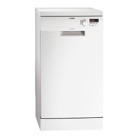
  9. AEG Oko-Favorit 50719 User manual

AEG Oko-Favorit 50719 User manual

Other AEG Dishwasher manuals

AEG FAVORIT 84470 User manual

AEG

AEG FAVORIT 84470 User manual

AEG FFB62427ZM User manual

AEG

AEG FFB62427ZM User manual

AEG FAVORIT COMPACT 505 User manual

AEG

AEG FAVORIT COMPACT 505 User manual

AEG FEB52610ZM User manual

AEG

AEG FEB52610ZM User manual

AEG FAVORIT 144 S User manual

AEG

AEG FAVORIT 144 S User manual

AEG FSK75778P User manual

AEG

AEG FSK75778P User manual

AEG FAVORIT 64660 User manual

AEG

AEG FAVORIT 64660 User manual

AEG F56302W0 User manual

AEG

AEG F56302W0 User manual

AEG FAVORIT 65022 I User manual

AEG

AEG FAVORIT 65022 I User manual

AEG FSS62807P User manual

AEG

AEG FSS62807P User manual

AEG OKO FAVORIT 5070 User manual

AEG

AEG OKO FAVORIT 5070 User manual

AEG FAVORIT 99015 I User manual

AEG

AEG FAVORIT 99015 I User manual

AEG FAVORIT 448 i User manual

AEG

AEG FAVORIT 448 i User manual

AEG FSK93700P User manual

AEG

AEG FSK93700P User manual

AEG FAVORIT 88072 User manual

AEG

AEG FAVORIT 88072 User manual

AEG FSK93800P User manual

AEG

AEG FSK93800P User manual

AEG FSE83617P User manual

AEG

AEG FSE83617P User manual

AEG FAV50879 User manual

AEG

AEG FAV50879 User manual

AEG FSE76727P User manual

AEG

AEG FSE76727P User manual

AEG FSE64606P User manual

AEG

AEG FSE64606P User manual

AEG FAVORIT 78400 VI User manual

AEG

AEG FAVORIT 78400 VI User manual

AEG OKO_FAVORIT 545 i User manual

AEG

AEG OKO_FAVORIT 545 i User manual

AEG FAVORIT 99015 VI User manual

AEG

AEG FAVORIT 99015 VI User manual

AEG LAVAMAT TRIATHLON 60820 User manual

AEG

AEG LAVAMAT TRIATHLON 60820 User manual

Popular Dishwasher manuals by other brands

Samsung DW-FN320T user manual

Samsung

Samsung DW-FN320T user manual

LG LDS 5811WW Service manual

LG

LG LDS 5811WW Service manual

Elba EDW-B1462D owner's manual

Elba

Elba EDW-B1462D owner's manual

VESTEL NOVUS Series Service manual

VESTEL

VESTEL NOVUS Series Service manual

Bosch SMS4EMW00E Instructions for use

Bosch

Bosch SMS4EMW00E Instructions for use

Global-Tek GT-CR 2 manual

Global-Tek

Global-Tek GT-CR 2 manual

Smeg Dishwasher 85028 Instructions for installation and use

Smeg

Smeg Dishwasher 85028 Instructions for installation and use

LG LD-4080W Service manual

LG

LG LD-4080W Service manual

Bauknecht GCF 625 operating instructions

Bauknecht

Bauknecht GCF 625 operating instructions

Sharp QW-HX13F47EI-EU user manual

Sharp

Sharp QW-HX13F47EI-EU user manual

Asko D5536XLFI operating instructions

Asko

Asko D5536XLFI operating instructions

Modena WP 7134 WVM User manual book

Modena

Modena WP 7134 WVM User manual book

Beko DFN39340X instruction manual

Beko

Beko DFN39340X instruction manual

Siemens SN23HI37VE user manual

Siemens

Siemens SN23HI37VE user manual

Maytag MDB4651AWB - Tall Tub Dishwasher User instructions

Maytag

Maytag MDB4651AWB - Tall Tub Dishwasher User instructions

Hotpoint Ariston LL 42 Instruction book

Hotpoint Ariston

Hotpoint Ariston LL 42 Instruction book

Siemens SN45ZW56CS user manual

Siemens

Siemens SN45ZW56CS user manual

Asko DFI766UXXL.AU user manual

Asko

Asko DFI766UXXL.AU user manual

manuals.online logo
manuals.online logoBrands
  • About & Mission
  • Contact us
  • Privacy Policy
  • Terms and Conditions

Copyright 2025 Manuals.Online. All Rights Reserved.

SERVICE MANUAL
© AEG Hausgeräte GmbH
Muggenhofer Straße 135
D-904 9 Nürnberg
Germany
Fax +49 (0)911 3 3 14 0
TSE - N
Publ.-Nr.:
599 50 84 90
685
10.00
EN
Edition:
DISHWASHER
Dishwasher
EDW 1000
(Mini-Tronic)
INTENSIV
70° ZEIT-
VORWAHL
50719
3 h
6 h
9 h
REINIGEN
EIN / AUS
TROCKNEN
ENDE
SALZ
KLARSPÜLER
NORMAL
65°
NORMAL
BIO 50° VOR-
SPÜLEN
QUICK
50°
INTENSIVE
70 °
NORMAL
65 °
NORMAL
BIO 50 °
QUICK
50 °
PRE
WASH
TIME
SELECTION CLEAN
DRY
END
SALT
DETERGENT
ON /
OFF
- 2 -
TSE-N 10.00 A. B. 599 50 84 90 EN
Index
1. Dimensions ............................................................................................................3
2. Typical features for use .........................................................................................4
3. Components ..........................................................................................................4
Interference Filter...................................................................................................4
Pressure Switc .....................................................................................................5
Flow Heater ...........................................................................................................5
Circulation Pump ...................................................................................................5
Drain Pump ............................................................................................................5
NTC Temperature Sensor .....................................................................................6
Detergent / Rinse Aid Combination Dispenser Unit ..............................................6
Electronic ...............................................................................................................6
Water Softening .....................................................................................................7
4. Position of Components.........................................................................................7
5. Water Course Sc eme ........................................................................................10
6. All-Around Water Protection ................................................................................11
Aqua-Control Inlet Hose ......................................................................................11
Safety level ..........................................................................................................11
Leakage Protection ..............................................................................................11
7. Water Inlet ...........................................................................................................13
8. Water load steps ..................................................................................................14
Static filling...........................................................................................................14
Dynamic filling ......................................................................................................15
9. New pulse was wit random functionality........................................................15
Circulation ............................................................................................................16
Function of t e new pulse was wit random functionality ...............................15
10. Sequence draining wit pressure switc level c eck...........................................17
New drain wit sequence draining .......................................................................17
Draining ...............................................................................................................18
11. Installation of t e Drain Hose...............................................................................19
12. Regeneration .......................................................................................................19
Rinse out after regeneration ................................................................................20
Regeneration .......................................................................................................20
13. In- and Output elements ......................................................................................21
Position of pus buttons, LEDs and lamps ...........................................................21
14. General ................................................................................................................22
15. Input-P ilosop y: C oose program- and options ................................................23
16. Input-P ilosop y: Programstart till -end ..............................................................24
17. Input-P ilosp y - delete, c ange, abort ...............................................................25
18. Program p ase display, Status display................................................................26
19. Adjust water ardness: ........................................................................................27
20. Service-functions for assembly line .....................................................................28
Assembly line test program .................................................................................28
21. Customer service functions .................................................................................29
Single actor activation ..........................................................................................29
Indication of customer service failure stack .........................................................29
Delete t e customer service failure stack and LED-test ......................................30
22. Misuse and program interrupt ..............................................................................30
23. Overview of Service and After sales functions ....................................................31
24. Overview of failure displays .................................................................................32
25. Programms and Options......................................................................................33
26. Description of t e options ....................................................................................34
27. Rinse, resin was , regeneration and measure ....................................................35
- 3 -
TSE-N 10.00 A. B. 599 50 84 90 EN
Build-in dimensions for Built-Under
Dishwashers
ÖKO-FAVORIT
Dimensions for Freestanding Dishwasher
Height 5 cm
Width 60 cm
Depth 60 cm
Height with worktop removed 2 cm
Feet adjustment 1 cm
1. Dimensions
Build-in dimensions for Fully Integrated
Dishwashers
ÖKO-FAVORIT
Build-in dimensions for Integrated
Dishwashers
ÖKO-FAVORIT
* Appliances wit
eig t
adjustable feet
* Appliances with height-adjustable feet
Plinth height for appliances 820 mm high
100 - 175 mm
Plinth height for appliances 870 mm high
150 - 230 mm
- 4 -
TSE-N 10.00 A. B. 599 50 84 90 EN
2. Typical features for use
3. Components
Interference Filter
T e interference filter is connected in t e terminal board parallel to
t e mains feed.
ÖKO-FAVORIT 50719 sensorlogic
Was programs: Intensive 70, Normal 65, Normal Bio 50,
Quick 50, Prewas Extra
Power consumption: 10 A
Heating: flow eater
Water consumption: 16 l
Energy Normal Bio 50 °C: 1.05 kW
Energy Normal 65 °C: 1.35 kW
Noise: 47 dB(A)
INTENSIV
70°ZEIT-
VORWAHL
50719
3 h
6 h
9 h
REINIGEN
EIN / AUS
TROCKNEN
ENDE
SALZ
KLARSPÜLER
NORMAL
65°
NORMAL
BIO 50°VOR-
SPÜLEN
QUICK
50°
INTENSIVE
70 °
NORMAL
65 °
NORMAL
BIO 50 °
QUICK
50 °
PRE
WASH
TIME
SELECTION CLEAN
DRY
END
SALT
DETERGENT
ON /
OFF
- 5 -
TSE-N 10.00 A. B. 599 50 84 90 EN
65 mm
11 12
14
16 17
45 mm
11 12
14
16 17
fS
fN fS
fN
Pressure Switch
T e pressure switc controls t e water level.
Wit out water, contact 11 - 12 is closed.
fN Switc point wit level 65 mm Ws
Reset point wit level 45 mm Ws
fS Switc point wit safety level 114 mm Ws
Reset point 90 mm Ws
T e pressure switc is not adjustable.
Flow Heater
T e flow eater eats t e water to t e required temperature. During
t e was cycle, water is contantly passing t roug t e flow eater.
Power output 2100 W
Resistor 25 W
Protector 98 °C ± 5 K
T ermal fuse 260 °C
Circulation Pump
T e circulation pump is driven by an async ronous motor wit an
auxiliary winding. T e auxiliary winding ist in circuit wit a 4 mF
capacitor. A tac o generator is used for speed control.
T ere are t ree speeds for rinsing.
2800 1/min, 2200 1/min, 1900 1/min, 1700 1/min, 1600 1/min, Power
output 50 W.
Drain Pump
T e drain pump is driven by a sync ronous motor.
Power output 26 W.
Pump rate 15 l/min.
- 6 -
TSE-N 10.00 A. B. 599 50 84 90 EN
NTC Temperature Sensor
Detergent / Rinse Aid Combination Dispenser Unit
Detergent dosage = 20 ml - 30 ml
Rinse Aid capacity 150 ml
Dosage settings 1 - 6
Quantity 1 cm3- 6 cm3
The detergent dispenser is activated by a release coil. The first operation
adds the detergent, and the second the rinse aid. If the door is opened,
the latching bar is reset to the detergent dosage position.
Electronic
On electronic models, a micro processor controls all components, this is
done using triacs. The electronic also memorizes all programme data.
T e eating is switc ed by a relay on t e electronic board.
NTC-Temperaturfühler
Temperature sensor NTC-resistor
Temperatur/Widerstand
2
0 °C / 6032 Ω
t
emperature/resistor
2
5 °C / 4829 Ω
(nur bei vollelektron. 30 °C / 3891 Ω
Geschirrspüler) 40 °C / 2573 Ω
(only for fully electronic dishw asher) 50 °C / 1741 Ω
55 °C / 1444 Ω
60 °C / 1204 Ω
65 °C / 1009 Ω
70 °C/849Ω
- 7 -
TSE-N 10.00 A. B. 599 50 84 90 EN
2
1
3
3
1
2
1
2
Water Softening
The components required for water softening.
1. softener unit
2. regeneration dosage chamber
The incoming water flows through the softener which works
according to the ion exchange principle. The ion exchanger is
filled with small epoxy resin balls. The resins exchange the
hardness constituents (calcium and magnesium), for sodium
ions.
When all the sodium ions are used up, it is necessary to
regenerate the softener. This is done by flushing a brine
solution through the softener.
Afterwards the softener is washed out with fresh water and is
now fully effective.
Depending on the water hardness, regeneration is only necessary after several wash cycles.
T e softening system is designed for a water ardness of up to 50 °dH.
4. Position of Components
Detergent dispenser (1)
Drying fan intake vent (2)
Spray arms (3)
Detergent dispenser (1)
Electronic (2)
- 8 -
TSE-N 10.00 A. B. 599 50 84 90 EN
23
1
1
2
3
1
2
Thermal sensor (1)
Drain pump (2)
Pressure switch (3)
Flow heater (1)
Terminal board (2)
Inlet valve (3)
To remove side panel :
1 Remove fixing screws
2 Pull t e panel away from t e rear, and gently out of t e
front trim.
Removing the regeneration dosage chamber :
1 disengage locking tabs (1)
2 disconnect oses (2)
3 olding t e top of t e c amber, pull upwards disengaging it
from t e softener.
- 9 -
TSE-N 10.00 A. B. 599 50 84 90 EN
1
1
Removing the softener unit :
1 remove t e securing nut located under t e salt cap.
2 press softener (1) down and remove it t roug t e front
from t e base area
3 CAUTION if accessible release reed switc .
Removing the base :
1 remove side panels, rear panel and plint panel
2 gently release base fixing clips wit a screwdriver (figure)
3 take off base carefully and release circulation pump,
electronic and eater relay
4 disconnect t e float switc
With base removed the circulation pump (1) is accessible.
- 10 -
TSE-N 10.00 A. B. 599 50 84 90 EN
22
21
21
24
23
7
23
1
12 65810 11 9
15 16 17
20
14
18
13
19
4
5. Water Course Scheme
1 Inlet valve
2 Air break
3 Regeneration water dosage
4 Overflow safety level
5 Safety overflow
6 Inlet to sump from regeneration dosage
c amber
7 Regeneration dosage c amber
8 Softener
9 Salt container
10 Non-return valve salt container
11 Regeneration valve
12 Safety inlet ose
13 Base tray
14 Float switc
15 Pressure switc
16 Filter
17 Circulation pump
18 Flow eater
19 Drain pump
20 Non-return valve
21 Spray arms
22 Roof-mounted s ower
23 Tub vent
24 Sump assembly