Aegis DataCell D User manual

INSTRUCTION MANUAL
DataCell D

Page 2 of 12
CZ21554-01
Congratulations on your purchase of an Aegis Pty Ltd DataCell.
We are sure you will be satisfied with its performance and reliability. Please
read these instructions carefully before using your DataCell and refer to
these notes from time to time to ensure you are always familiar with its
operation.
Safety Warning
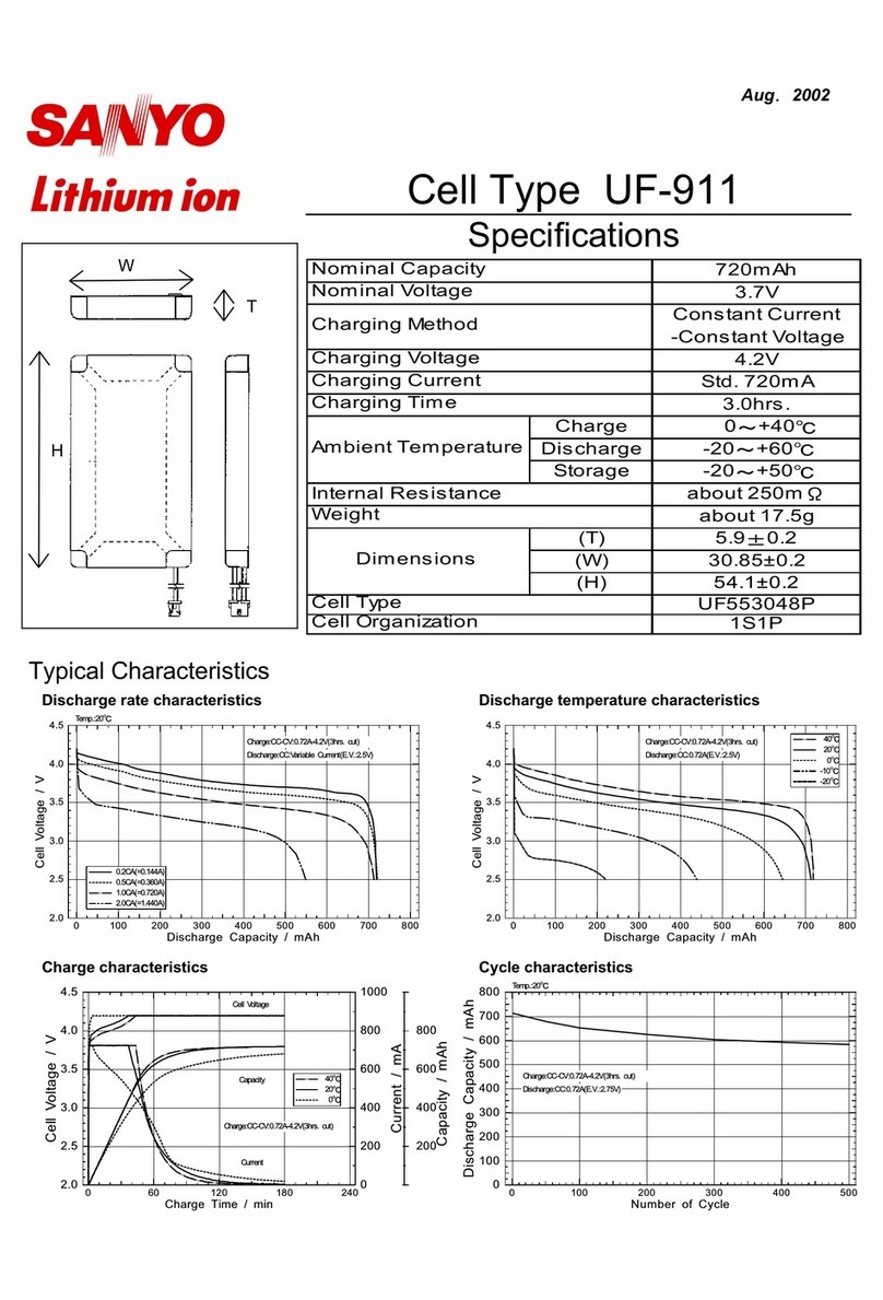
• This product contains pri ary lithiu battery cells.
• Any use of the product contrary to that described in this user
anual ay present risk of personal injury, high
te peratures, fire or explosion and will void any perfor ance
specifications of the product.
• Do not open, da age, puncture, incinerate, or expose to
te peratures above 55°C.
• Transport and dispose of in accordance with anufacturer
instructions and local regulations.
• Do not use this product if it is da aged in any way.
Aegis Pty Ltd can also supply many instruments for a number of applications
to support installation and maintenance of cabling for the telecommunications,
Data and Electrical industries.
If you re uire further information on any of these instruments, please contact
us by way of the phone, fax or e-mail.
200 Rooks Road, Ver ont, Victoria 3133 AUSTRALIA
TELEPHONE: (03) 8872 6666 FACSIMILE: (03) 8872 6678
International Prefix +613
Email: sales@aegis.net.au
WEB: www.aegis.net.au
!
!!
!

Page 3 of 12
CZ21554-01
Table of Contents
1. INTRODUCTION .................................................................................................. 4
2. INSTALLATION ................................................................................................... 4
2.1. Mounting ........................................................................................................... 4
2.2. Bottom Panel Layout ........................................................................................ 4
2.3. Input connections.............................................................................................. 5
3. WORKING WITH A DATACELL D ...................................................................... 6
3.1. Exiting Hibernation............................................................................................ 6
3.2. Waking the DataCell D ..................................................................................... 6
3.3. Communicating with a DataCell D .................................................................... 7
3.4. LED indications................................................................................................. 7
4. CARE AND MAINTENANCE................................................................................ 7
4.1. Warranty ........................................................................................................... 7
4.2. Maintenance and Servicing............................................................................... 7
4.3. Cleaning............................................................................................................ 7
5. SPECIFICATIONS ............................................................................................... 8
5.1. Inputs ................................................................................................................ 8
5.2. Communications ............................................................................................... 8
5.3. Logging ............................................................................................................. 8
5.4. Electrical ........................................................................................................... 8
5.5. Physical ............................................................................................................ 8
5.6. Environmental................................................................................................... 8
5.7. Applicable Standards........................................................................................ 8
5.8. Standard Accessories....................................................................................... 9
5.9. Optional Accessories ........................................................................................ 9
6. OTHER PRODUCTS IN THE DATACELL RANGE ........................................... 10

Page 4 of 12
CZ21554-01
1. INTRODUCTION
The DataCell D has been designed to give you reliable and accurate data logging of
metering and industrial processes in all environments. Commissioning and data
collection is done locally via the DataCell’s optical port using the Infrared Cable (IRC)
and a notebook PC.
Once installed, the DataCell D should continue to operate without further adjustment
for the expected life of its batteries. Typical operation parameters can be changed by
using the Infra Red Cable and the Connect software suite. This software is available
via internet download from the resources page at www.DataCell.co or by contacting
Aegis.
2. INSTALLATION
2.1. Mounting
The DataCell D is designed to be mounted in an upright position. Select a suitable
mounting location, considering operational issues such as clearances from objects
that may cause physical damage to the unit. Mount the supplied bracket using an
appropriate fixing mechanism ensuring the product is mounted securely and cannot
be dislodged. Fasten the product in place by fixing the supplied screws through the
bracket and into the bracket mounting holes as shown in Fig 2.2.
2.2. Botto Panel Layout
1
2
3
4
5
6
6
6
6
Key to Fig 2.2
1. Input 1 programmable input.
2. Input 2 programmable input with protective cap.
3. Input 3 programmable input with protective cap.
4. Input 4 programmable input with protective cap.
5. IRC Receptacle: Infrared communications port.
6. Bracket mounting holes.

Page 5 of 12
CZ21554-01
2.3. Input connections
There are four sockets on the bottom of the DataCell D. These are the inputs for the
DataCell data logger to connect to various sensors. Three inputs will have a cap
covering the input sockets to protect them from damage when not in use, see fig 2.2.
The connections for the input sockets at the bottom of the unit are as follows:
R: Return (internal Ground)
L: Line
T: Tamper
See figure 2.3 below, for details of a typical connection to a water meter ‘switch type’
(reed switch) sensor. The sensor cable outer diameter must be between 4.5 – 6.5mm.
Figure 2.3 Typical water eter sensor connections
METER
Input R
Ta per
Input L
Tamper
Input R
Input L
Notch
Sensor Cable
Tamper
Input R
Input L
Rear View of Plug
Gasket
Clamp Ring
Seal EPDM
Sealing Nut
Plug
One of four Input
sockets on the
base of unit

Page 6 of 12
CZ21554-01
3. WORKING WITH A DATACELL D
3.1. Exiting Hibernation
To allow transport and storage of the DataCell D, without concern of generating unnecessary logging
activity, the unit is placed into hibernation prior to leaving the factory. To exit hibernation hold the
DataCell D in a position whereby you can view the activity of the LED’s within the infrared
communications port and follow the following steps:-
1. Hold the magnet in the location shown in figure 3.2.1 and observe that the Yellow LED is lit. Keep
the magnet in place for approximately 10 seconds until the Orange LED illuminates.
2. Upon illumination of the orange LED remove the magnet from its position and hold it away from the
DataCell for a period of approximately 10 seconds, at the completion of which the Red LED will
illuminate.
3. Return the magnet to the original position; soon a Green LED will flash at which time you should
swipe the unit three (3) times, by moving the magnet left to right across the label as shown in figure
3.2.1. This will temporarily cause the LED’s to shut down before returning to the high power state
with both the Green and Orange LED’s Illuminated.
3.2. Waking the DataCell D
Once the DataCell D has exited Hibernation it can be woken by using the swipe magnet as follows:-
Using the Swipe Magnet from the IRC Starter Kit, swipe the magnet over the side of the unit directly in
line with the IRC port using a downward swiping action, see fig 3.2.1.
Figure 3.2.1 Waking the DataCell D
Swipe Magnet

Page 7 of 12
CZ21554-01
3.3. Co unicating with a DataCell D
To communicate with the DataCell D you must use the Connect software suite. Configuration changes
may only be made locally via the Infrared cable. All information and instructions regarding the
configuration, set up and data collection of the DataCell D can be found in the Connect User Guide
which is available online at www.datacell.co.
3.4. LED indications
LED’s are provided to give the user an indication of what activity the DataCell is undertaking at any given
time. These LED’s are visible via the infrared communications port and have various activity states as
described below:-
Both LED’s OFF. Unit in low power or sleep mode.
Green OFF, Orange ON. Logging disabled, Unit in High power mode.
Green On, Orange ON. Logging enabled, Unit in High power mode.
4. CARE AND MAINTENANCE
4.1. Warranty
The DataCell D is warranted against defects in materials and workmanship for a period of 12 months
from the date of purchase as per the standard Aegis terms and conditions of Warranty. For purposes of
warranty repair or replacement, the user is re uired to return the defective item together with proof of
purchase to AEGIS at the address given in this section below. Aegis is not responsible for any incidental
or conse uential damages resulting from the breach of any express or implied warranty including
damage to property and to the extent permitted by law damages for personal injury. Aegis does not
assume liability or responsibility for any loss or damage resulting from the use of this device.
4.2. Maintenance and Servicing
The DataCell D contains no user-serviceable parts and any damaged or failed instruments should be
returned to the manufacturer for repair. Such units should be cleaned, suitably packaged, and
transported in accordance with local regulations to:
Aegis Pty Ltd.
200 Rooks Rd, Ver ont, Victoria, Australia, 3133
The sender’s name and return address must be supplied, together with a description of the fault.
If different from the return address, an invoicing address should also be given.
4.3. Cleaning
Warning: Potential electrostatic charging hazard.
Only wipe product with a damp cloth.
Do not wipe with solvent.

Page 8 of 12
CZ21554-01
5. SPECIFICATIONS
5.1. Inputs
Up to 4 unpowered floating Voltage free inputs.
Short cable mode: - Max input cable length 4 metres
Long cable mode: - Max input cable length 10 metres
5.2. Co unications
Serial: Infrared interface
5.3. Logging
Memory: 2 million records
Alarms: Low or Zero usage in a period
High usage in a period
Return of state
Tamper detection
Clock: Real time with time and date stamp
5.4. Electrical
Inputs: Maximum output current 270µA DC @ 2.7V DC
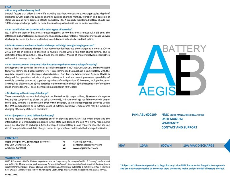
Power Source: 1 x primary lithium battery cell (3.6V@14AH)
Battery Life: Typically 10 years at 1 channel, 5 minute logging
5.5. Physical
Dimensions 88mmØ x 170mm
Weight 470 grams
5.6. Environ ental
IP Rating: IEC 529 (1989): IP68
AS 1939-1990: IP68
Temperature:
Operating Temperature: -20°C to +55°C
Storage Temperature: Preferably not exceeding 30ºC
Pressure: 80 kPa to 110 kPa
5.7. Applicable Standards
IEC 529 (1989): IP68
AS 1939-1990: IP68
C-Tick
Manufactured under a Quality System complying to ISO9001 (QEC Lic.5948)

Page 9 of 12
CZ21554-01
5.8. Standard Accessories
Accessory Qty Part No
Bracket 1 CZ21269
Screws 4 M4X20 PAN HD XR S/S
M12 Male Inline Plug 1 CZ21512
Cap M12 3 CZ21511
5.9. Optional Accessories
Accessory Qty Part No
IRC Starter Kit USB 1 CZ21036
M12 Male Inline Plug 4 CZ21512
Cap M12 4 CZ21511

Page 10 of 12
CZ21554-01
6. OTHER PRODUCTS IN THE DATACELL RANGE
DataCell Atx
The top of the range DataCell Atx provides monitoring and recording of analogue and
digital signals. E uipped with 4 fully programmable inputs and two-way GSM/GPRS
communications the highly flexible DataCell Atx is the cornerstone of any remote
monitoring and reporting application.
DataCell Rtx
Widely used in utility metering and industrial logging and alarming applications, the
DataCell Rtx was the first unit of the DataCell range to deliver superior features such
as two-way communications for remote programming and live time updates. With a
storage capacity of 2 million records, the always reliable DataCell Rtx delivers “set and
forget” monitoring in all environments.
DataCell Rtx Ex
Independently certified for IEC Ex Zone 0 applications, the DataCell Rtx Ex delivers all
of the features of a standard Rtx with the additional benefit of being certified for
installation within hazardous zones without the need for additional and expensive
protective barriers.
DataCell GPS
Specifically developed for customers looking to track the time date and location where
water tankers extract from hydrants, the DataCell GPS delivers GPS location data with
pin point accuracy.
DataCell L
Intrinsically safe for use in sewers the DataCell L provides early warning of rising
levels in sewer and other level monitoring applications. Optioned with 2 or 3 floats the
DataCell L is designed to give sufficient warning of a surge before an expensive clean
up is re uired.

Page 11 of 12
CZ21554-01
NOTES:-

Page 12 of 12
CZ21554-01
Aegis Pty Ltd
200 Rooks Road, Ver ont, Victoria 3133 AUSTRALIA
International Prefix +613
E ail: sales@aegis.net.au
WEB: www.aegis.net.au
WEB: www.datacell.co
Table of contents
Other Aegis Camera Accessories manuals
Aegis
Aegis ABL-60050P User manual

Aegis
Aegis ABL-48010P User manual

Aegis
Aegis ABL-24060P User manual

Aegis
Aegis ABL-48012P User manual

Aegis
Aegis ABL-12055P User manual

Aegis
Aegis ABL-24015P User manual

Aegis
Aegis ALF-048100A User manual

Aegis
Aegis ALF-016015P User manual

Aegis
Aegis ABL-12030P User manual

Aegis
Aegis ABL-36060P User manual

Aegis
Aegis ABL-60010P User manual

Aegis
Aegis ABL-48025P User manual

Aegis
Aegis ABL-48060P User manual

Aegis
Aegis ABL-52010P User manual

Aegis
Aegis ABL-14010P User manual

Aegis
Aegis LITHIUMASTER ABL-12045P User manual
Aegis
Aegis ABL-24012P User manual

Aegis
Aegis ALF-012300A User manual

Aegis
Aegis ABL-60060P User manual

Aegis
Aegis ABL-60030P User manual