AEM CD-5FLG User manual

2
Introduction
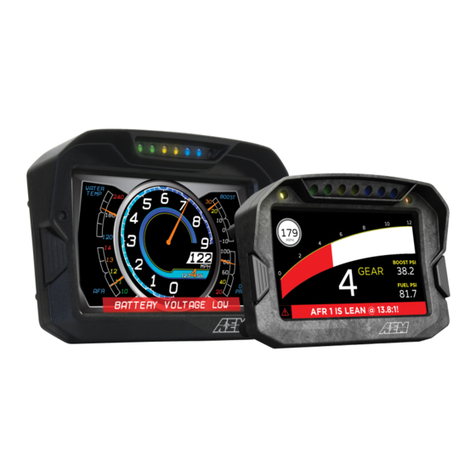
The purpose of this Quick Start Guide is to provide an overview of the installation and setup of the CAN Display (CD)
dash. This guide assumes that an AEM-supplied pre-configured layout file is to be used which greatly simplifies the
setup process. If not using a pre-configured layout or choosing to make changes beyond what is covered beyond
the scope of this guide, please refer to the full CD dash user manual located in
Documents\AEM\DashDesign\Instructions. The document is installed as part of the software installation process.
Software Installation
AEM DashDesign is distributed as a single install executable. To install, visit aemelectronics.com and click on
Software Downloads and navigate to CD Dash/DashDesign. Download the software and then run the AEM
DashDesign Setup.exe and follow the on-screen instructions including restarting computer if prompted to do so. If
using the logging version of dash, also download and install AEMdata for downloading and analyzing data logs.
USB Drivers
The installation program will automatically install the USB drivers required for the CD dash. However, on rare
occasions, it may be necessary to install the USB drivers manually. To do this:
·
Connect the CDdash to the PCwith the USB comms cable
·
When the add new hardware wizard appears, select "Install froma list or specific location" and click Next
·
Choose "Search for the best driver in these locations" and check "Include this location in the search"
·
Clickthe Browse button and navigate to the Drivers folder sub folder in the AEMDashDesign installation directory: C:\ProgramFiles (x86)
\AEM\DashDesign\CD-X_Drivers
·
Clickthe Next button and the driver installation will proceed automatically.
Hardware Installation
The CD dash is designed for use in closed and open cockpit motorsports, marine and motorcycle use. The CD dash
enclosure is IP65 rated for protection against dust and low pressure water spray. Mount the CD dash with good line
of sight with the driver/rider using the included anti-vibe mounts. The last page of this Quick Start Guide is a
mounting template for the dash.
Wiring
Two wiring harnesses are included with the dash kit. One is the main harness that plugs into the back of the dash
with leads for the AEMnet/Port 1 and Port 2 CAN inputs. The other is a power harness that plugs into the 4 pin
AEMnet connector. This power harness is used to supply power and ground to the dash. It is only necessary if
connecting to a non-AEM harness or an AEMNet connector with only 2 pins terminated. See Figure 1 and Figure 2.
It is not necessary if you are connecting your dash to a harness manufactured by AEM that includes an AEMNet
connector with all 4 pins populated. See Figure 3.

3
Figure 1 - Connecting CDdash to non-AEMnet devices requires that included power harness be used to supply power and
ground to the dash. Red and black wires from power harness connector should be connected to switched, fused 12v
power and ground, respectively.
Figure 2 - Connecting CDdash to AEMnet devices with only a 2 wire interface requires that the included power harness be
used to supply power and ground to the dash. Add the two CANsignal wires for a complete connection. Red and black
wires from power harness connector should be connected to switched, fused 12v power and ground, respectively.

4
Figure 3 - Connecting CDdash to AEMnet devices that have four wires present in their AEMnet connector is "plug and
play" because the transmit device is providing power, ground and CAN communications through their AEMnet connector.
Included power harness should not be used.

5
Figure 4 - Connector Interfaces
CD DASH PINOUT
PIN
WIRE
COLOR
FUNCTION
NOTES
1
RED
12V POWER
Connect to switched, fused +12v power source
2
BLACK
GROUND
Ensure good ground connection that isn't shared with high
noise emitters such as ignition systems
3
WHITE
AEMNET/PORT 1
CAN+
CAN+; typically reserved for AEMnet devices; use twisted
pair wiring to minimize signal noise
4
GREEN
AEMNET/PORT 1
CAN-
CAN-; typically reserved for AEMnet devices; use twisted
pair wiring to minimize signal noise
5
SILVER
PORT 2
CAN+
CAN+; for use with third party CAN devices; use twisted pair
wiring to minimize signal noise
6
BLACK
PORT 2
CAN-
CAN-; for use with third party CAN devices; use twisted pair
wiring to minimize signal noise
7
NOT
POPULATED
PAGEUP
*OPTIONAL* Remote Page Up (left dash button) input; use
momentary switch to ground
8
NOT
POPULATED
RESET
*OPTIONAL* Remote Reset (right dash button) input; use
momentary switch to ground
9
GRAY
NIGHT MODE
*OPTIONAL* Triggers Night Mode to dim dash display;
connect to 12v dash lights circuit
10
VIOLET
BEACON
*OPTIONAL* Sets start/finish line beacon if using GPS for
track mapping; use momentary switch to ground
11
NOT
POPULATED
SPARE1
*OPTIONAL* Spare switch input; typically used for turn
signals; switch must connect to ground
12
NOT
POPULATED
SPARE2
*OPTIONAL* Spare switch input; typically used for turn
signals; switch must connect to ground

6
Figure 5 - CANconnector port pinouts
PORT 1/AEMnet
PORT 2
PIN
WIRE
COLOR
FUNCTION
PIN
WIRE
COLOR
FUNCTION
1
WHITE
Port 1/AEMnet CAN+
1
SILVER
Port 2 CAN+
2
GREEN
Port 1/AEMNet CAN-
2
BLACK
Port 2 CAN-
3
RED
+12v Power
4
BLACK
Ground
Communication Cables
The CD dash comes in two primary versions: logging and non-logging. Logging CD dashes come with two USB
comms cables: one sealed bulkhead cable and one standard cable. The bulkhead cable is to be permanently
connected to the dash and mounted in an accessible location to allow for more frequent connections in order to
download data logs. Non-logging dashes come with a standard USB comms cable for dash configuration.
Uploading Layout File
AEM provides ready to use layout files that are pre-configured for use with popular engine management systems and
other CAN devices. Files for many popular systems are available and more are being added continuously.
Start by opening the DashDesign software and go File>Open and navigate to
Documents\AEM\DashDesign\Setups\App Specific in the DashDesign directory to find the appropriate layout file for
the CAN device being used with the CD dash. The pre-configured file will have all of the display elements in the
layout correctly assigned to the appropriate channel inputs being received from the CAN device that the dash is
paired with. No additional layout changes should be necessary.
With the dash powered on, connect the dash to the PC using the USB comms cable – check that the status bar is
green and indicates that the CD dash is connected. To upload the layout file go to File>Upload to Display or use
keyboard short cut CTRL+U. File upload transfer progress can be monitored on the dash screen. USB comms
cable can be disconnected once the status bar is green and indicates “Upload Complete, OK to disconnect”. Do

7
NOT disconnect the USB cable before this message appears. When the USB cable is disconnected from the PC,
the dash will reset and then display the loaded layout file.
Figure 6 - Status bar in DashDesign software. Do NOT disconnect USBcable until OK to disconnect message is shown.
Uploading Firmware
It’s good practice to ensure that the CD dash is loaded with the latest firmware. To upload firmware to the dash,
open DashDesign software, connect the CD dash to the PC using the USB comms cable - check that status bar is
green and indicates that the CD dash is connected - and go Tools>Upload Firmware. Locate CD7-XXxXX.bin file and
click Open. Status bar will be blue during firmware upload and then turn green and indicate “Firmware upload OK”
when complete.

8
Dash Interface
Figure 7 - Dash Interfaces
LEDs
All LEDs are configured by going to Setup>Shift Lights and LEDs.
·
Amber - No dedicated function. Is triggered by alarm channels only. Custom triggering criteria possible.
·
Red - No dedicated function - is commonly used for MIL/CEL. Is triggered by alarm channels only. Custom
triggering criteria possible.
·
Shift Lights - LED color from left to right: green, green, amber, amber, blue, blue blue. To set up shift light, click
on Auto Create Outputs in Shift Light Setup to launch Shift Light Wizard.
oOutput - Set to channel to be referenced. This is typically EngineSpeed.
oStart - Set to the rpm at which to light the first green LED
oOffset - Sets the rpm increment to light the next LED.
Shift Light Wizard Example: Take total shift light rpm range (flash rpm - start rpm) and divide by 7 (total number of
LEDs). For instance, to have shift light start at 5000 rpm and flash at 7000 rpm, set offset to 285 (7000-5000/7).
Buttons
Buttons are accessible directly from the face of the dash itself or may be remotely mounted (on steering wheel, etc)
- see Optional Wiring.
·
Left - Page Up. Press once to move to next display screen. Press to clear Alarm Screen and return to regular
display pages.
·
Right - Reset. Resets any count up, count down or lap timers that are currently being shown on the displayed
screen.

9
Track Mapping VDM, GPS Module or Internal GPS
An AEM Vehicle Dynamics Module (VDM; 30-2206) or GPS Module (30-2207) can be paired with a CD dash to
provide GPS data for race track mapping and lap timing. The module is added to the Port 1/AEMnet network using
the AEMnet connector "Y" in its cable – see Figure 8 and VDM/GPS Module instruction manual for full installation
guidelines. Products with internal GPS capabilities like the CD-5 can be connected as shown in Figure 9.
Figure 8 - Track Mapping with 30-2206 VDM or 30-2207 GPS Module

10
Figure 9 - Track Mapping with CD-5 with internal GPS
If using the AEM 5 Gauge layout file, the GPS channels are already configured and no additional setup is
necessary. To add GPS channels to a layout that doesn’t already have them, start by opening the desired layout
file and then go Setup>Display, click on CAN Receive tab, select Port 1 and then click on Import CAN button.
Locate the VDM/GPS Module dbc file, select either US or SI units and click Open. CAN Import window will open
showing all channels available for import – leave all channels selected and click on Import. All VDM/GPS channels
(listed below) have now been added to the Outputs channel list.
GPS Latitude
GPS Satellite Count
GPS Hours
Acceleration Z*
GPS Longitude
GPS Valid
GPS Minutes
YawRate X*
GPS Speed
GPS Year
GPS Seconds
YawRate Y*
GPS Altitude
GPS Month
Acceleration X*
YawRate Z*
GPS Course
GPS Day
Acceleration Y*
*VDMonly
Lap timing can be set up once the GPS channels have been imported. Go Setup>Lap Timing and the software
should automatically recognize the newly added GPS channels and assign them accordingly. If the channels aren’t
set automatically, simply match the following example. If using a product with internal GPS, the GPS channels will
include an "i" suffix after "GPS". For example "GPSi_Speed". The Show Predefined Outputs in the Setup Editor
option must be checked for these channels to appear in the output list. External and internal GPS setup examples
are shown below.

11
With track mapping configured, the race vehicle can be driven on track to collect GPS data. At the exact moment
when crossing the start/finish line, the lap beacon button should be pressed and held momentarily until both the
amber and red LEDs flash on the dash. The lap beacon button is an external input that must be added using the
violet wire input. See Figure 4. The flashing LEDs indicate that the start/finish line GPS coordinates have been
successfully set. Each time the vehicle crosses the start/finish line, a new lap will be counted and lap timer will
reset – see below for definitions of lap timing channels from AEM 5 Gauge layout.

12
AEM CAN Sensor Module
An AEM 22 Channel CAN Sensor Module (30-2212) can be paired with a CD dash to provide analog, digital and
frequency signals for display and logging. The module is added to the Port 1/AEMnet network using the AEMnet
connector "Y" in its cable – see diagram. See CAN Sensor Module instruction manual for full installation guidelines.
AEM has supplied a number of pre-configured layouts for use with the CAN Sensor Module. The file name of each
layout describes the vehicle setup that the layout has been configured for. Vehicle setups include carburated or fuel
injected, drag race or road race, with or without AEM VDM and US or SI units. All layouts are based on the
suggested channel assignments listed in the pinout in the CAN Sensor Module instructions.
Channel Calibration
The channel data sent from the CAN Sensor Module is in a "raw" form such as voltage, frequency or resistance.
Inputs from sensors such as pressure transducers or temperature sensors can use a predefined transfer function to
go from raw units to engineering units. Other channels such as Vehicle Speed, Fuel Level and Throttle Position will
require that a calibration be performed in order to get the channel to report accurately. See the 30-2212 manual for
more details.
·
Vehicle Speed - Base units is frequency. A scalar is applied to the raw frequency to get speed in MPH. The
calibration is scalar = (tire diameter inches * 0.18)/number of speed sensor trigger teeth. For example, the scalar
for a 26" tire and 12 teeth on the speed sensor trigger is (26 * 0.18)/12 which is 0.390. To set the Vehicle Speed
scalar, go Setup>Display>Scalars and locate VehicleSpeed_scalar. Using provided calibration calculation will get
speed reading very close but speed calibration can be verified with a dyno or GPS. To decrease Vehicle Speed,
decrease the VehicleSpeed_scalar value.
·
Fuel Level - Base units is Ohms. A function table is used to assign a fuel level percentage to an Ohms value.
To adjust the function table go Setup>Display>Functions and locate FuelLevelCalibration. While monitoring live
data, note the Ohms value when the tank is completely empty and also when completely full. If the change in
level sensor resistance is linear to fuel usage, the table can be left with empty and full values only. If the fuel tank
is oddly shaped and the change in level sensor resistance does not represent a linear change in fuel usage, the
function table can be setup to report a fuel level for each gallon added to the fuel tank from empty to give a more
accurate reading.
·
Throttle Position - Base units is volts. A function table is used to assign a throttle position percentage to a
voltage value. To adjust the function table go Setup>Display>Functions and locate ThrottlePosCalibration. While

13
monitoring live data, note the voltage value when the throttle is completely closed and also when completely open.
Assign the closed throttle voltage to 0 and the full open throttle voltage to 100.
Data Logging
If using logging version of CD dash, logging can be configured by going to Setup>Logging to open the Logging Setup
window. Here, channels can be selected to be logged and at what capture rate. Logging a specific channel also
automatically selects all other children and parent channels for logging at the same rate.
The log can be started in one of three ways:
·
Single input start/stop - When the specified input is non zero, the log will be started. When zero, the log will be
stopped. For example, if the channel EngineSpeed is used as the trigger, the logger will log anytime the engine is
running.
·
Twin start/stop triggers - When the Start trigger is non zero, the log will be started. When the Stop trigger is non
zero, the log will be stopped.
·
Log Always - The logging starts logging immediately on power on and will log until switched off or until the log is
full.
To download log files from the CD dash, launch AEMdata, power the dash on and connect the comms cable to
bulkhead cable USB port. A Logger Detected message will be shown once the AEMdata software connects with the
dash. In the message, click on Download Data, select the files to be saved and click Ok. Select a save location,
name the file and click on Save.

14
Drill Template
Drill template prints to scale.
This manual suits for next models
2
Table of contents
Other AEM Monitor manuals

