AEM LS Series Owner's manual

CONFIDENTIAL AND PROPRIETARY TO ANODYNE ELECTRONICS MANUFACTURING CORP.
INSTALLATION AND OPERATION MANUAL
REV 1.11 October 4, 2017
Anodyne Electronics Manufacturing Corp.
15-1925 Kirschner Road
Kelowna BC, Canada
V1Y 4N7
Telephone (250) 763-1088
Facsimile (250) 763-1089
Website: www.aem-corp.com
© 2016 Anodyne Electronics Manufacturing Corp. (AEM),
All Rights Reserved
ASM-LS
LSxxx
Series
High Power Loud Speaker

LSxxx Series High Power Loud Speaker
Installation and Operation Manual
Installation and Operation Manual Page ii
ENG-FORM: 820-0100.DOTX
CONFIDENTIAL AND PROPRIETARY TO ANODYNE ELECTRONICS MANUFACTURING CORP.
COPYRIGHT STATEMENT
© 2016 Anodyne Electronics Manufacturing Corp. (AEM), All Rights
Reserved
This publication is the property of AEM and is protected by Canadian
copyright laws. No part of this document may be reproduced or transmitted
in any form or by any means including electronic, mechanical,
photocopying, recording, or otherwise, without the prior written permission
of AEM.

LSxxx Series High Power Loud Speaker
Installation and Operation Manual
Installation and Operation Manual Page iii
ENG-FORM: 820-0100.DOTX
CONFIDENTIAL AND PROPRIETARY TO ANODYNE ELECTRONICS MANUFACTURING CORP.
Prepared By:
Checked By:
Approved By:
The status of this installation and operation manual is controlled by the revision shown on the title page.
The status of each section is controlled by revision shown in the footer of each page. All revisions
affecting sections of this manual have been incorporated.
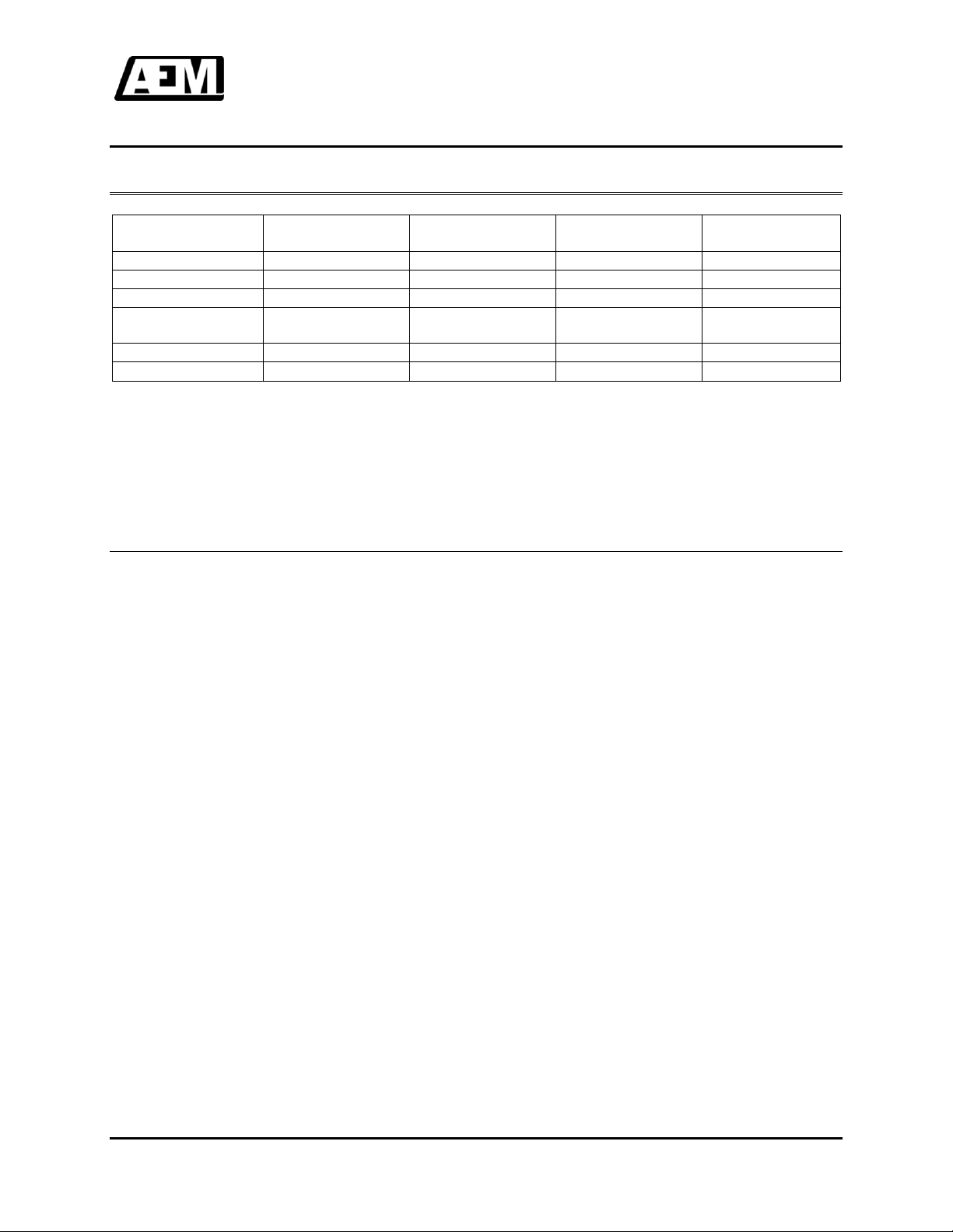
AEM MANUAL REVISIONS
Section
Revision Number
Revision Description
Date
2.3
Rev 1.11
RAS#708: Corrected Meeker PN’s
October 4, 2017
2.3
Rev 1.10
RAS#589: Updated Mechanical
Installation section.
May 13, 2016
All
Rev 1.00
Initial Release
April 24, 2015
Tony Pearson
Designer
Oct 4, 2017
Duane Stewart
Designer
Oct 4/17
Tom Betzelt
Product Support
Manager
Oct 5 2017
Ron Briggs
R&D Mgr
Designate
Oct 02/18

LSxxx Series High Power Loud Speaker
Installation and Operation Manual
Installation and Operation Manual Page iv
ENG-FORM: 820-0100.DOTX
CONFIDENTIAL AND PROPRIETARY TO ANODYNE ELECTRONICS MANUFACTURING CORP.
Table of Contents
Section Title Page
1.0 Description
1.1 Introduction 1-1
1.2 Product Description 1-1
1.3 Design Features 1-2
1.4 Specifications 1-2
1.4.1 Electrical Specifications 1-2
1.4.2 Physical Specifications 1-2
1.4.3 Environmental Specifications 1-2
1.5 System Configuration 1-3
2.0 Installation
2.1 Introduction 2-1
2.2 Unpacking and Inspection 2-1
2.2.1 Warranty 2-1
2.3 Installation Procedures 2-1
2.3.1 Warnings 2-1
2.3.2 Cautions 2-2
2.3.3 Cabling and Wiring 2-2
2.3.4 Mechanical Installation 2-2
2.3.5 Post-Installation Checks 2-3
2.4 Accessories Required But Not Supplied 2-3
2.5 Continued Airworthiness 2-3
2.6 Speaker Location and Orientation 2-4
2.7 Installation Drawings 2-6
3.0 Operation
3.1 Operation Specifics 3-1

LSxxx Series High Power Loud Speaker
Installation and Operation Manual
October 4, 2017 Rev: 1.11 Page 1-1
ENG-FORM: 800-0100.DOTX
CONFIDENTIAL AND PROPRIETARY TO ANODYNE ELECTRONICS MANUFACTURING CORP.
Section 1.0 Description
1.1 Introduction
Information in this section consists of product description, design features and specifications for the
LSxxx Series High Power Loud Speakers.
Review all notes, warnings and cautions.
1.2 Product Description
The LSxxx Series Loud Speakers are high output power loud speakers for use in air-to-ground, air-to-sea, or
ground-to-ground audible communication systems. The LSxxx Series speakers are intended for use with the
LSA400 or LSA800 series amplifiers and asiren controller as a complete system.
Siren Controller
Loud Speaker Amplifier
Loud Speakers

LSxxx Series High Power Loud Speaker
Installation and Operation Manual
October 4, 2017 Rev: 1.11 Page 1-2
ENG-FORM: 800-0100.DOTX
CONFIDENTIAL AND PROPRIETARY TO ANODYNE ELECTRONICS MANUFACTURING CORP.
1.3 Design Features
This series of speakers is available in a single, double, or triple bell configuration, which allows the user to
vary the range and/or dispersal pattern depending on the mounting configurations.
The speaker drivers have been updated to provide much better conversion of electrical power (Watts) to
sound pressure (SPL).
The driver assembly and newly designed mechanical parts are field replaceable for ease of maintenance.
The LSxxx Series speakers are designed and qualified to meet many operational roles of current and
future light, medium, and heavy helicopters as well as fixed wing aircraft.
1.4 Specifications
1.4.1 Electrical Specifications
Loudspeaker
Total Bell
Configuration
Impedance
Rated Peak
Power
Output Level
@ 1m & Rated
Peak Power
Weight
LS300-200
1
5.5 Ω
300 Watts
Peak
130dB
15 lbs
[6 kg]
LS600-200
2
2 Channels at
5.5 Ω each
600 Watts
Peak
135dB
28 lbs
[12.7 kg]
At the time of publication, performance information was available only for the speakers listed above. For
details of other units, please contact the Product Support department at AEM.
1.4.2 Physical Specifications
See Mechanical Installation drawings (LSxxx-xxx-922-0) for speaker physical specifications
(where x is the model reference of the specific unit under consideration, i.e. LS300-200-922-0)
1.4.3 Environmental Specifications
Temperature -40 to +60C (operating)
-55 to +85C (survival)
Altitude +25,000 ft. (+7,620 m) max.
Humidity 95% Non-condensing
Shock 6g (any axis)
Vibration DO-160G Category ‘S’Curves B & M
and Category ‘U2’ Curves F & F1
Magnetic Effect DO-160G category ‘B’
LSxxx Series High Power Loud Speaker
Installation and Operation Manual
October 4, 2017 Rev: 1.11 Page 1-3
ENG-FORM: 800-0100.DOTX
CONFIDENTIAL AND PROPRIETARY TO ANODYNE ELECTRONICS MANUFACTURING CORP.
1.5 System Configuration
Loud Speaker
Total Bell
Configuration
Amplifier
Input Power
Output Level
@ 1m
LS300-200
1
LSA400
28 Vdc
130dB
LS600-200
2
LSA400
28 Vdc
135dB
LS600-200
2
LSA800
28 Vdc
135dB
1 X LS300-200
1 X LS600-200
3
LSA800
28 Vdc
137dB
2 X LS300-200
2
LSA800
28 Vdc
135dB
2 X LS600-200
4
LSA800
28 Vdc
141dB
At the time of publication, performance information was available only for the speakers listed above. For
details of other units, please contact the Product Support department at AEM.
End of Section 1.0

LSxxx Series High Power Loud Speaker
Installation and Operation Manual
October 4, 2017 Rev: 1.11 Page 2-1
ENG-FORM: 805-0100.DOTX
CONFIDENTIAL AND PROPRIETARY TO ANODYNE ELECTRONICS MANUFACTURING CORP.
Section 2.0 Installation
2.1 Introduction
Information in this section consists of: unpacking and inspection procedures, installation procedures,
post-installation checks, and installation drawings.
2.2 Unpacking and Inspection
Unpack the equipment carefully. Inspect the unit visually for damage due to shipping and report all such
claims immediately to the carrier involved. Note that each unit should have the following:
- LSxxx Series High Power Loud Speaker
- Product Information Card
- Certificate of Conformity or Release Certification
Verify that all items are present before proceeding and report any shortage immediately to your supplier.
2.2.1 Warranty
All Anodyne Electronics Manufacturing Corp. (AEM) products are warranted for 2 years. See the website
www.aem-corp.com/warranty for complete details.
2.3 Installation Procedures
2.3.1 Warnings
WARNING:
When the speaker is connected to an appropriate amplifier, the system
is capable of producing high sound pressure levels. Proper personal
protective equipment is required to prevent hearing damage.
Stand clear, this equipment operates at an intense sound level.
Personnel must be kept away from the direct loud speaker beam.
LSxxx Series High Power Loud Speaker
Installation and Operation Manual
October 4, 2017 Rev: 1.11 Page 2-2
ENG-FORM: 805-0100.DOTX
CONFIDENTIAL AND PROPRIETARY TO ANODYNE ELECTRONICS MANUFACTURING CORP.
2.3.2 Cautions
CAUTION:
Do not operate the equipment in a hangar or in confined areas.
Do not operate the equipment with snow, water or other foreign matter in the
loud speaker horn.
Do not clean the loud speaker with compressed air.
Bundle and route the Speaker Output wires separately from low level Audio
Input lines.
Always check ADF and compass calibration after installing external speakers
or power amplifiers.
2.3.3 Cabling and Wiring
All wire shall be selected in accordance with the original aircraft manufacturer's Maintenance Instructions
or AC43.13-1B Change 1, Paragraphs 11-76 through 11-78. Unshielded wire types shall qualify to MIL-
W-22759 as specified in AC43.13-1B Change 1, Paragraphs 11-85, 11-86, and listed in Table 11-11. For
shielded wire applications, use Tefzel MIL-C-27500 shielded wire with solder sleeves (for shield
terminations) to make the most compact and easily terminated interconnect. Follow the interconnect
drawing in Section 2.7 as required.
Allow 3" from the end of the shielded wiring to the shield termination to allow the connector hood to be
easily installed. Refer to the interconnect drawing in Section 2.7 for shield termination details. Note that
the hood is a "clamshell" hood, and is installed after the wiring is complete. Aircraft harnessing shall
permit the unit to be removed for easy access to all adjustments.
Maintain wire segregation and route wiring in accordance with the original aircraft manufacturers
Maintenance Instructions.
2.3.4 Mechanical Installation
The installing agency is responsible for the design, engineering and installation of the mounting bracket
for the LSxxx Series High Power Loud Speakers. Careful consideration should be given to the operating
environment and the mechanical forces acting upon the LSxxx Series unit(s).
The guidelines used in the AC43.13-1B Advisory Circular should be used to provide general reference to
the selection of hardware, torque values, etc. The specific references are contained in AC43.13-1B,
Chapter 7, Table 7-1.
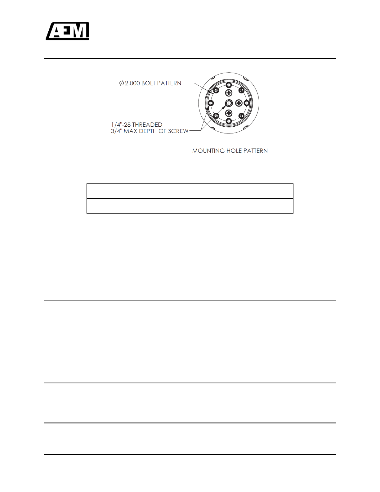
A minimum of five mounting 1/4“-28 bolts per side is recommended for the LS300-200 and LS600-200
speakers. The bolts should have a torque value of 50 –70 inch lbs as per the AC43.13-1B. Refer to the
following diagram for the mounting hole pattern.
LSxxx Series High Power Loud Speaker
Installation and Operation Manual
October 4, 2017 Rev: 1.11 Page 2-3
ENG-FORM: 805-0100.DOTX
CONFIDENTIAL AND PROPRIETARY TO ANODYNE ELECTRONICS MANUFACTURING CORP.
The LSxxx-200 series of loud speakers, Rev 2.00 or later, can be mounted using the AFM-SB-XX series
of Meeker Aviation mount brackets.
AEM Part Number
Required Meeker Aviation
Mounting Bracket
LS300-200
AFM-SB-1-1C
LS600-200
AFM-SB-1-1A
For information and availability of the AFM-SB-XX series of mounting brackets contact Meeker Aviation:
Meeker Aviation
#206 19142 122nd Ave
Pitt Meadows, BC
Canada V3Y 2P9
PH: 604-644-1125
FAX: 760-758-9612
www.meekeraviation.com
2.3.5 Post-Installation Checks
Ensure all connectors are tight and the speaker array mechanical installation is sound.
Ensure that the speakers are secure and adjusted with the line of sight focused towards the intended
target. See section 2.6 for speaker location and orientation information.
When the PA system installation is complete, carry out a full performance test to ensure that all
components of the system (including the loud speaker array) are functioning correctly.
2.4 Accessories Required But Not Supplied
LS300-IK LS300 and LS600 90° Sealed Screw Terminal Installation Kit
2.5 Continued Airworthiness
Maintenance of the LSxxx Series is ‘on condition’ only. Periodic maintenance of this product is not
required.
LSxxx Series High Power Loud Speaker
Installation and Operation Manual
October 4, 2017 Rev: 1.11 Page 2-4
ENG-FORM: 805-0100.DOTX
CONFIDENTIAL AND PROPRIETARY TO ANODYNE ELECTRONICS MANUFACTURING CORP.
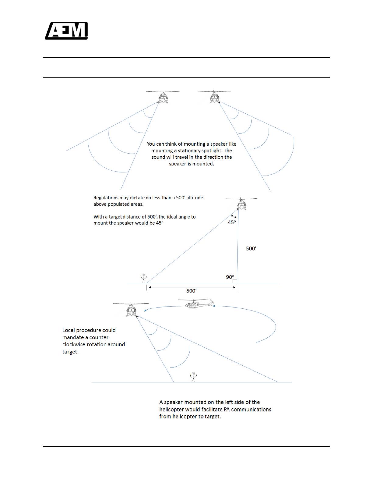
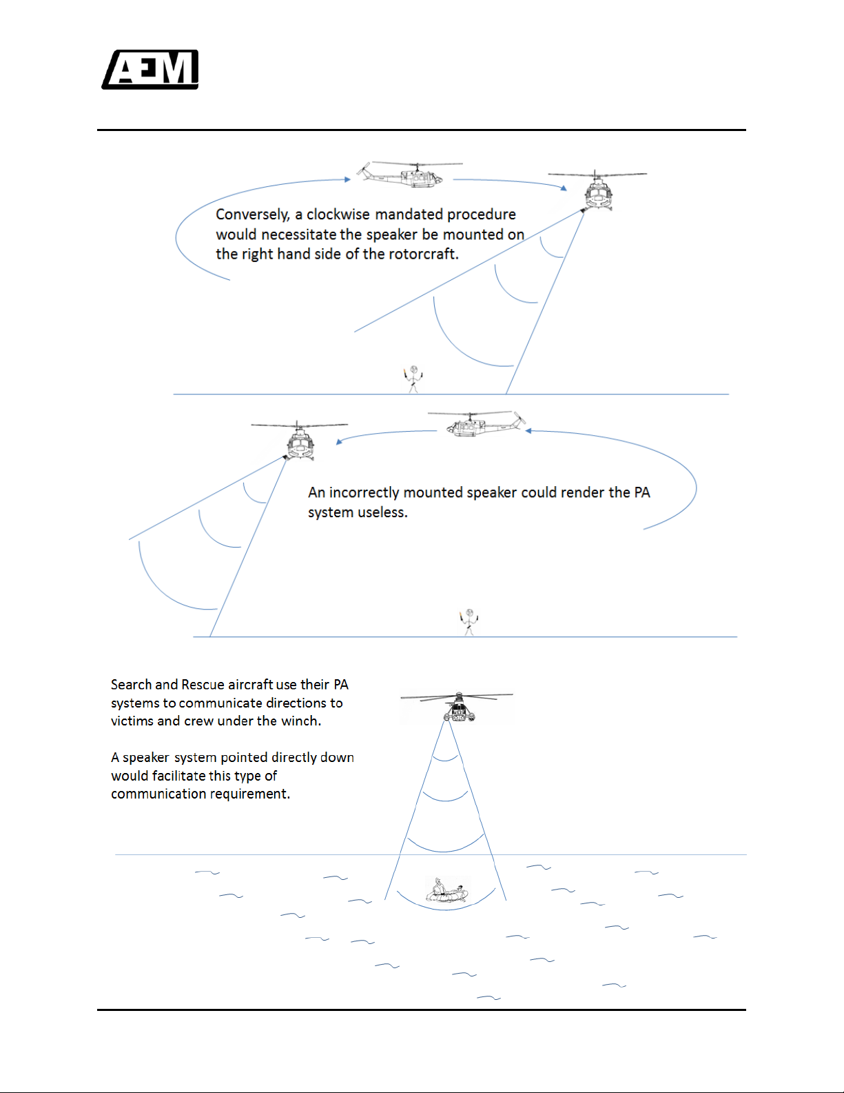
2.6 Speaker Location and Orientation
LSxxx Series High Power Loud Speaker
Installation and Operation Manual
October 4, 2017 Rev: 1.11 Page 2-5
ENG-FORM: 805-0100.DOTX
CONFIDENTIAL AND PROPRIETARY TO ANODYNE ELECTRONICS MANUFACTURING CORP.

LSxxx Series High Power Loud Speaker
Installation and Operation Manual
October 4, 2017 Rev: 1.11 Page 2-6
ENG-FORM: 805-0100.DOTX
CONFIDENTIAL AND PROPRIETARY TO ANODYNE ELECTRONICS MANUFACTURING CORP.
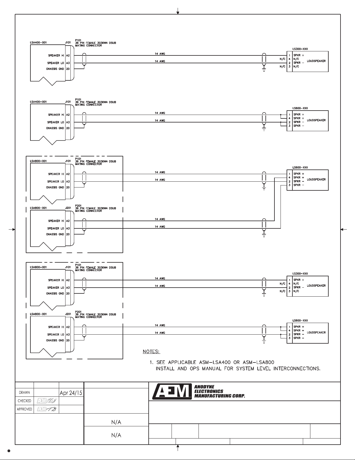
2.7 Installation Drawings
DRAWING
REV.
DESCRIPTION
TYPE
SERIAL NO.
LSxxx-403-0
1.00
Loud Speaker Configurations
Interconnect
All
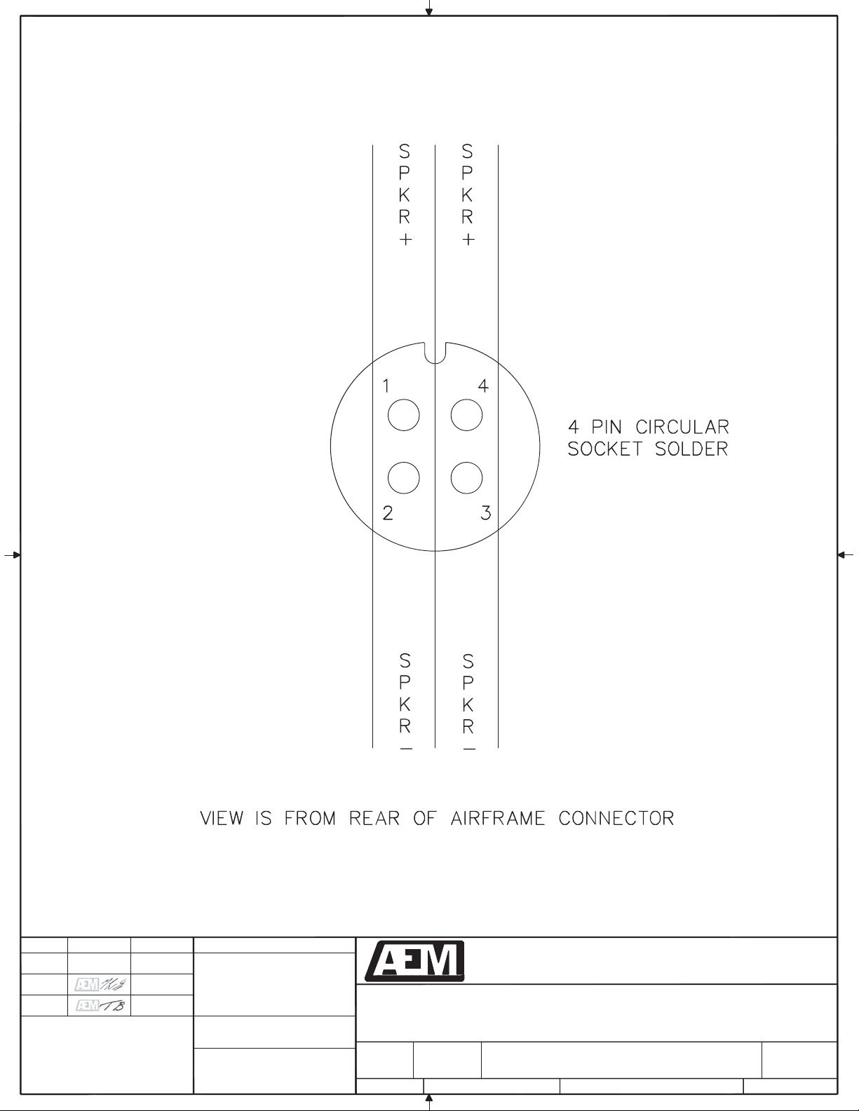
LS300-405-0
2.00
Loud Speaker, LS300
Connector Map
1006 and up
LS300-405-0
1.00
Loud Speaker, LS300
Connector Map
Up to 1005
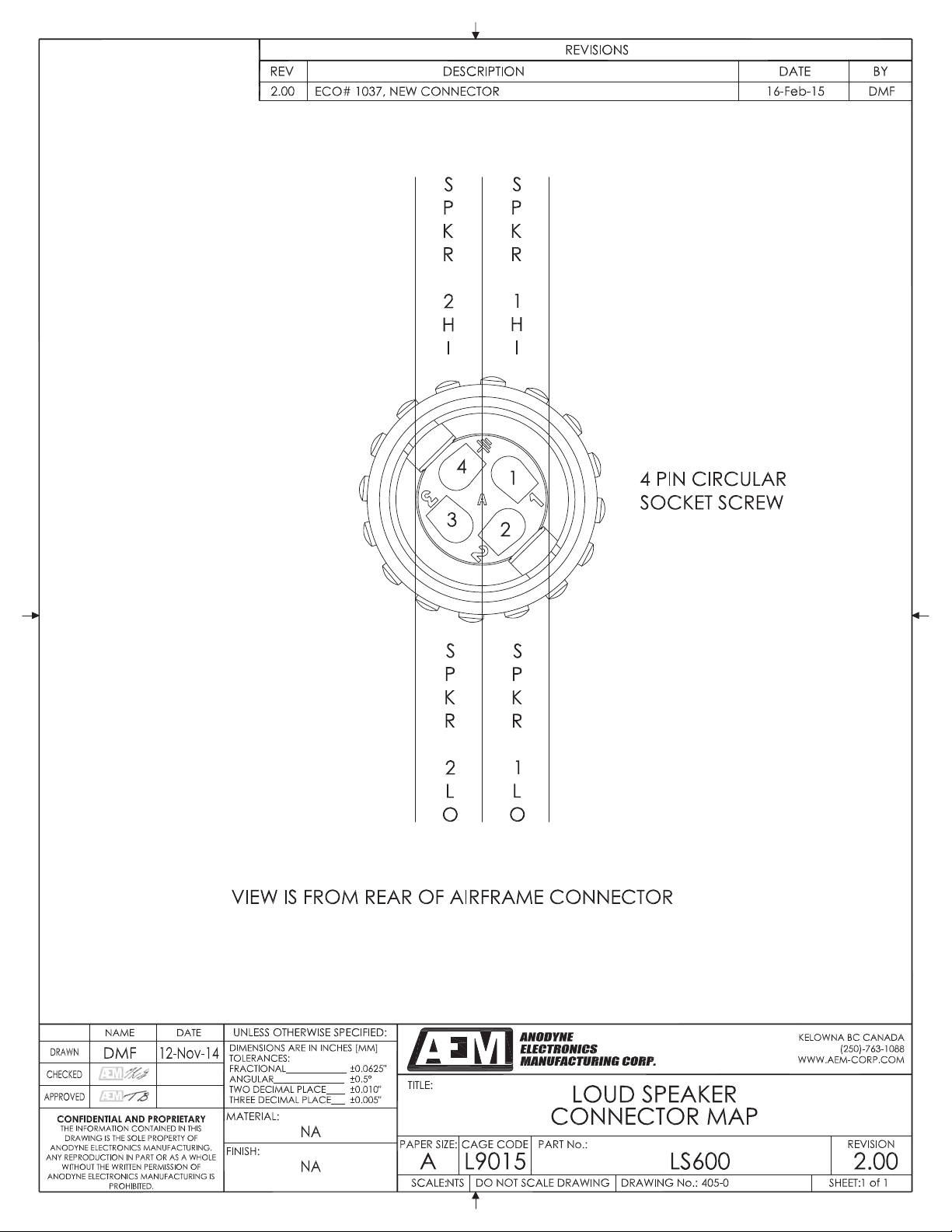
LS600-405-0
2.00
Loud Speaker, LS600
Connector Map
1006 and up
LS600-405-0
1.00
Loud Speaker, LS600
Connector Map
Up to 1005
LS300-200-922-0
2.00
Loud Speaker, LS300
Mechanical Installation
1006 and up
LS300-200-922-0
1.10
Loud Speaker, LS300
Mechanical Installation
Up to 1005
LS600-200-922-0
2.00
Loud Speaker, LS600
Mechanical Installation
1006 and up
LS600-200-922-0
1.00
Loud Speaker, LS600
Mechanical Installation
Up to 1005
Section 2.0 ends following the above documents
SHEET:
UNLESS OTHERWISE SPECIFIED:
SCALE:
REVISION
PART No.:
A
PAPER SIZE:
TITLE:
NAME DATE
FINISH:
MATERIAL:
DIMENSIONS ARE IN INCHES [MM]
THE INFORMATION CONTAINED IN THIS
DRAWING IS THE SOLE PROPERTY OF
ANODYNE ELECTRONICS MANUFACTURING.
ANY REPRODUCTION IN PART OR AS A WHOLE
WITHOUT THE WRITTEN PERMISSION OF
ANODYNE ELECTRONICS MANUFACTURING IS
PROHIBITED.
CAGE CODE
CONFIDENTIAL AND PROPRIETARY
L9015
KELOWNA BC CANADA
(250)-763-1088
WWW.AEM-CORP.COM
DO NOT SCALE DRAWING
TOLERANCES:
FRACTIONAL_____________
ANGULAR_______________
TWO DECIMAL PLACE____
THREE DECIMAL PLACE___
±0.0625"
±0.5°
±0.010"
±0.005"
DRAWING No.:
LSxxx 1.00
1:1 1 of 2
LAC
LOUD SPEAKER CONFIGURATIONS
INTERCONNECT
403-0
A
pr 24/15
A
pr 28/15

SHEET:
UNLESS OTHERWISE SPECIFIED:
SCALE:
REVISION
PART No.:
A
PAPER SIZE:
TITLE:
NAME DATE
FINISH:
MATERIAL:
DIMENSIONS ARE IN INCHES [MM]
THE INFORMATION CONTAINED IN THIS
DRAWING IS THE SOLE PROPERTY OF
ANODYNE ELECTRONICS MANUFACTURING.
ANY REPRODUCTION IN PART OR AS A WHOLE
WITHOUT THE WRITTEN PERMISSION OF
ANODYNE ELECTRONICS MANUFACTURING IS
PROHIBITED.
CAGE CODE
CONFIDENTIAL AND PROPRIETARY
L9015
KELOWNA BC CANADA
(250)-763-1088
WWW.AEM-CORP.COM
DO NOT SCALE DRAWING
TOLERANCES:
FRACTIONAL_____________
ANGULAR_______________
TWO DECIMAL PLACE____
THREE DECIMAL PLACE___
±0.0625"
±0.5°
±0.010"
±0.005"
DRAWING No.:
LSxxx 1.00
1:1 2 of 2
LAC
LOUD SPEAKER CONFIGURATIONS
INTERCONNECT
403-0
A
pr 24/15
A
pr 28/15

16-Feb-14
A
pr 28/15

SHEET:
UNLESS OTHERWISE SPECIFIED:
SCALE: DRAWING No.:
REVISION
PART No.:
A
PAPER SIZE:
TITLE:
NAME DATE
FINISH:
MATERIAL:
DIMENSIONS ARE IN INCHES [MM]
THE INFORMATION CONTAINED IN THIS
DRAWING IS THE SOLE PROPERTY OF
ANODYNE ELECTRONICS MANUFACTURING.
ANY REPRODUCTION IN PART OR AS A WHOLE
WITHOUT THE WRITTEN PERMISSION OF
ANODYNE ELECTRONICS MANUFACTURING IS
PROHIBITED.
CAGE CODE
CONFIDENTIAL AND PROPRIETARY
L9015
KELOWNA BC CANADA
(250)-763-1088
WWW.AEM-CORP.COM
DO NOT SCALE DRAWING
TOLERANCES:
FRACTIONAL_____________
ANGULAR_______________
TWO DECIMAL PLACE____
THREE DECIMAL PLACE___
±0.0625"
±0.5°
±0.010"
±0.005"
LS300 1.00
405-0NTS 1 of 1
DMF
LOUD SPEAKER
CONNECTOR MAP
12-Nov-14
Nov 14/14
16-Feb-14
A
pr 9/15
SHEET:
UNLESS OTHERWISE SPECIFIED:
SCALE: DRAWING No.:
REVISION
PART No.:
A
PAPER SIZE:
TITLE:
NAME DATE
CHECKED
DRAWN
FINISH:
MATERIAL:
DIMENSIONS ARE IN INCHES [MM]
THE INFORMATION CONTAINED IN THIS
DRAWING IS THE SOLE PROPERTY OF
ANODYNE ELECTRONICS MANUFACTURING.
ANY REPRODUCTION IN PART OR AS A WHOLE
WITHOUT THE WRITTEN PERMISSION OF
ANODYNE ELECTRONICS MANUFACTURING IS
PROHIBITED.
CAGE CODE
CONFIDENTIAL AND PROPRIETARY
APPROVED
L9015
ANODYNE
ELECTRONICS
MANUFACTURINGCORP.
KELOWNA BC CANADA
(250)-763-1088
WWW.AEM-CORP.COM
DO NOT SCALE DRAWING
TOLERANCES:
FRACTIONAL_____________
ANGULAR_______________
TWO DECIMAL PLACE____
THREE DECIMAL PLACE___
±0.0625"
±0.5°
±0.010"
±0.005"
LS600 1.00
405-0NTS 1 of 1
DMF
13-Nov-14
NA
NA
LOUD SPEAKER
CONNECTOR MAP
13-Nov-14
16-Dec-14

2.000 BOLT PATTERN
1.49
37.8
4.96
126
6.6 MAX
168 MAX
6.6 MAX
168 MAX
3.25
82.6 32.6
1.28
A
3.4
86
260 MAX
10.3 MAX
SCALE 2 : 5
MOUNTING HOLE PATTERN
DETAIL A
1/4"-28 THREADED
3/4" MAX DEPTH OF SCREW
IS THE SOLE PROPERTY OF ANODYNE
(250)-763-1088
0.100"
WWW.AEM-CORP.COM
NAME DATE
DRAWN
CHECKED
APPROVED ONE DECIMAL PLACE
FRACTIONAL______________
TOLERANCES:
0.030"
_______
CONFIDENTIAL AND PROPRIETARY
ELECTRONICS MANUFACTURING IS PROHIBITED.
UNLESS OTHERWISE SPECIFIED:
MATERIAL:
FINISH:
SCALE: 1:5 DRAWING No. : 922-0
PAPER SIZE:
A
TITLE:
CAGE CODE
L9015
LOUD SPEAKER
MECHANICAL INSTALLATION
LS300-200 REVISION
2.00
PART No. :
N/A
DO NOT SCALE DRAWING
N/A SHEET: 1 OF 1
DMF
0.0625"
KELOWNABCV1Y4N7
15-1925KIRSCHNERRD.
REPRODUCTION IN PART OR AS A WHOLE
ELECTRONICS MANUFACTURING. ANY
14-Nov-14
WITHOUT THE WRITTEN PERMISSION OF ANODYNE
_____
THREE DECIMAL PLACE 0.010"
______
TWO DECIMAL PLACE
THE INFORMATION CONTAINED IN THIS DRAWING
ANGULAR_________________ 0.5
DIMENSIONS ARE IN INCHES [MM]
12.8 MAX
325 MAX
7.8 MAX
198 MAX
5.0 MAX
126 MAX
5.79
147.1
167.9
6.61
NOTES:
MASS 15 lbs [6.8 kg] MAX.1.
DENOTES CENTER OF GRAVITY (est.)2.
REVISIONS
REV. DESCRIPTION DATE NAME
2.00 ECO# 1037, NEW DESIGN AFTER VIBRATION TESTING 02-Mar-15 DMF
11-Mar-15
A
pr 28/15
This manual suits for next models
2
Table of contents
Other AEM Speakers manuals


Popular Speakers manuals by other brands


Philips
Philips Fidelio DS8800W/10 quick start guide

Federal Signal Corporation
Federal Signal Corporation Global G-SPA Series quick start guide

Mitchell
Mitchell uStream Go user guide

Innovative Technology
Innovative Technology ITSBO-530 instruction manual

Pure Acoustics
Pure Acoustics BQ260 installation instructions

LG
LG NA6550WO manual


