AEM BAA01 User manual

CONFIDENTIAL AND PROPRIETARY TO ANODYNE ELECTRONICS MANUFACTURING CORP.
INSTALLATION AND OPERATION MANUAL
Document # IOBAA01-001
REV 1.01 July 25, 2023
Anodyne Electronics Manufacturing Corp.
966 Crowley Ave Unit #100
Kelowna, BC, Canada.
V1Y 0L1
Telephone: +1-250-763-1088
Toll Free: +1-888-763-1088
Website: www.aem-corp.com
© 2023 Anodyne Electronics Manufacturing Corp. (AEM),
All Rights Reserved
ASM-BAA01-001
Bluetooth Audio Accessory

BAA01-001 Bluetooth Audio Accessory
Installation and Operation Manual
Rev. 1.01 July 25, 2023
Page i
ENG-FORM 804-0100.DOTX
CONFIDENTIAL AND PROPRIETARY TO ANODYNE ELECTRONICS MANUFACTURING CORP.
COPYRIGHT STATEMENT
© 2023 Anodyne Electronics Manufacturing Corp. (AEM), All Rights Reserved
This publication is the property of AEM and is protected by Canadian copyright laws.
No part of this document may be reproduced or transmitted in any form or by any means
including electronic, mechanical, photocopying, recording, or otherwise, without the prior written
permission of AEM.

BAA01-001 Bluetooth Audio Accessory
Installation and Operation Manual
Rev. 1.01 July 25, 2023
Page ii
ENG-FORM 804-0100.DOTX
CONFIDENTIAL AND PROPRIETARY TO ANODYNE ELECTRONICS MANUFACTURING CORP.
Prepared By:
Checked By:
Approved By:
AEM MANUAL REVISIONS
Section
Rev.
Revision Description
Date
All
1.00
Initial release.
18-Nov-2022
All
1.01
ECO1158, multiple clarifications were added throughout
the document. Notable changes include:
1. Clarification on the use of the ART S/T Key
2. Post-installation check requirements
3. Section 2.8 Airworthiness Approval
4. Section 2.9 Instructions for Continued Airworthiness
5. Installation Drawing Revisions updated
25-Jul-2023
Steven Vetter
Technical Writer
27-Jul-2023
Tony Pearson
Designer
27-Jul-2023
Nikolis Andrews
Designer
28-Jul-2023
Todd Blackstock
Program
Manager
31-Jul-2023

BAA01-001 Bluetooth Audio Accessory
Installation and Operation Manual
Rev. 1.01 July 25, 2023
Page iii
ENG-FORM 804-0100.DOTX
CONFIDENTIAL AND PROPRIETARY TO ANODYNE ELECTRONICS MANUFACTURING CORP.
Table of Contents
SECTION 1.0 DESCRIPTION.....................................................................................................1
1.1 Introduction..................................................................................................................1
1.2 Product Description.....................................................................................................1
1.3 Design Features..........................................................................................................1
1.4 Specifications ..............................................................................................................2
1.4.1 Electrical Specifications...................................................................................2
1.4.2 Physical Specifications ....................................................................................4
1.4.3 Environmental Parameter - RTCA/DO-160G ...................................................5
1.5 Product Approval/Certification .....................................................................................5
1.5.1 United States - FCC.........................................................................................6
1.5.2 Canada - ISED.................................................................................................7
1.5.3 Europe - CE.....................................................................................................8
1.5.4 Japan - MIC.....................................................................................................8
1.5.5 Korea - KCC....................................................................................................8
1.5.6 Taiwan - NCC..................................................................................................9
1.5.7 China - SRRC..................................................................................................9
1.5.8 Brazil - ANATEL...............................................................................................9
1.6 Product Limitations....................................................................................................10
1.7 Product Identifier Description.....................................................................................10
SECTION 2.0 INSTALLATION.................................................................................................11
2.1 Introduction................................................................................................................11
2.2 Unpacking and Inspection..........................................................................................11
2.3 Installation Configurations..........................................................................................11
2.3.1 BAA01 In-Line between the Headset and Audio Controller............................12
2.3.2 BAA01 Installation in a Transceiver Position of the Audio Controller..............13
2.3.3 BAA01 Multi-Unit Installation..........................................................................14
2.4 Warranty....................................................................................................................15
2.5 Installation Procedure................................................................................................15
2.5.1 Warnings .......................................................................................................15
2.5.2 Cautions........................................................................................................15
2.5.3 Cabling and Wiring ........................................................................................15
2.5.4 Pre-Installation Checks..................................................................................16
2.5.5 Bonding.........................................................................................................16
2.5.6 Post-Installation Checks ................................................................................17
2.6 Adjustments and Connections...................................................................................17
2.7 Accessories Required but Not Supplied.....................................................................17
2.8 Airworthiness Approval..............................................................................................18
2.9 Instructions for Continued Airworthiness....................................................................18
2.10 Installation Drawings...............................................................................................20
SECTION 3.0 OPERATION......................................................................................................21
3.1 Introduction................................................................................................................21
3.2 General......................................................................................................................21
3.2.1 Connecting a Bluetooth Device......................................................................21
3.2.2 Bluetooth Troubleshooting.............................................................................22
3.2.3 Virtual Assistant Operation (Siri, Google, Alexa, etc..) ...................................23

BAA01-001 Bluetooth Audio Accessory
Installation and Operation Manual
Rev. 1.01 July 25, 2023
Page iv
ENG-FORM 804-0100.DOTX
CONFIDENTIAL AND PROPRIETARY TO ANODYNE ELECTRONICS MANUFACTURING CORP.
3.3 Modes of Operation...................................................................................................23
3.3.1 Emergency Mode (EMERG) ..........................................................................24
3.3.2 Normal Mode (NORM)...................................................................................25
3.3.3 Bluetooth Mute (BT MUTE)............................................................................26
3.3.4 Cellular Call Isolate (ISO) ..............................................................................27
3.4 Controls and Indicators..............................................................................................28
3.4.1 Volume Knob.................................................................................................28
3.4.2 Multicolour LED Annunciator..........................................................................32
3.4.3 Audible Annunciations ...................................................................................33
3.5 Maintenance Mode....................................................................................................33
3.6 Panel Backlighting & Annunciators............................................................................36
3.7 Charging Ports...........................................................................................................36
3.7.1 Front USB-C Charging Port ...........................................................................36
3.7.2 Rear Connector Charging Port.......................................................................37
3.7.3 Charging Protection.......................................................................................37
3.7.4 Charging Priority............................................................................................37

BAA01-001 Bluetooth Audio Accessory
Installation and Operation Manual
Rev. 1.01 July 25, 2023
Page 1 of 37
ENG-FORM 804-0100.DOTX
CONFIDENTIAL AND PROPRIETARY TO ANODYNE ELECTRONICS MANUFACTURING CORP.
Section 1.0 Description
1.1 Introduction
Information in this section consists of product description, design features and
specifications for the BAA01-001 Bluetooth® Audio Accessory, herein subsequently
referred to as the BAA01.
Review all notes, warnings, and cautions.
1.2 Product Description
The BAA01 Bluetooth Audio Accessory is a panel mount unit which adds a Bluetooth
wireless audio connection to an existing avionics, audio, PA or loudspeaker system.
The BAA01 supports music/call audio using the built-in Bluetooth audio profiles. The
power, pairing and link status is provided by built-in front panel LED annunciators.
Control and volume of the Bluetooth audio playback can be adjusted using the
BAA01’s built in front panel volume knobs. Figure 1: BAA01 Product Photo shows the
front of the BAA01 and the front facing user controls that are applicable to each
Bluetooth user.
Figure 1: BAA01 Product Photo
1.3 Design Features
The BAA01 is able to accommodate two simultaneous Bluetooth users with each user
having individual paired devices and volume control. Each Bluetooth user’s phones
output is factory configured to use stereo audio but can be individually configured in the
field to utilize mono audio. The volume knob can be used to adjust the volume of a
Bluetooth user, answer/end phone calls, start/stop audio playback, control a virtual
assistant (Siri®, Google®, Alexa®, etc..) and connect to a Bluetooth device. The status
of each Bluetooth user is shown by a dedicated multicolour LED annunciator that is
integrated into the front panel.
Volume Knob
User One Controls
User Two Controls
Mode Selector Knob
Volume Knob
USB-C and LED Annunciator
USB-C and LED Annunciator

BAA01-001 Bluetooth Audio Accessory
Installation and Operation Manual
Rev. 1.01 July 25, 2023
Page 2 of 37
ENG-FORM 804-0100.DOTX
CONFIDENTIAL AND PROPRIETARY TO ANODYNE ELECTRONICS MANUFACTURING CORP.
By using the mode selector knob in the center of the BAA01, the BAA01 can be placed
into 5 different modes of operation: EMERG, NORM, BT MUTE, ISO 1, ISO 2. Using
these modes, the audio from the Bluetooth users can be set to mute audio, isolate call
audio from the audio controller or alter the audio routing to bypass the BAA01 circuitry.
The BAA01 can be connected to compatible audio controllers or peripheral controllers.
To support various installation configurations, the BAA01 is equipped with the following
audio features:
a) Factory configured stereo headphone output and configurable for mono operation.
b) Mono microphone input with built in microphone bias and a buffered microphone
output. This supports passthrough of cabin microphone audio.
c) Mono phones input that is summed with the configurable sidetone and Bluetooth
audio which is presented on the phone output.
d) Field accessible maintenance mode to adjust audio levels and select mono/stereo
headphones output.
e) Two front facing USB-C ports and one rear USB connection (must be manually
wired) for device charging.
f) All legends on the BAA01 are backlight with IPL white. Brightness control is
achieved by varying the voltage on the appropriate lights input (5V or 28V).
g) Dedicated artificial sidetone key for each Bluetooth user to provide sidetone when
the audio controller does not provide sidetone.
1.4 Specifications
1.4.1 Electrical Specifications
1.4.1.1 Power Requirements:
Idle: 0.4 A Max. @ +28.0 Vdc
Maximum: 2.6 A Max. @ +28.0 Vdc
Lighting: 10 mA Max. @ +28.0 Vdc
10 mA Max @ +5.0 Vdc
1.4.1.2 Input Operating Voltage:
Normal Operating Conditions
Maximum Operating Voltage: +30.3 Vdc
Nominal Operating Voltage: +28.0 Vdc
Minimum Operating Voltage: +22.0 Vdc
Emergency Operating Voltage: +18.0 Vdc

BAA01-001 Bluetooth Audio Accessory
Installation and Operation Manual
Rev. 1.01 July 25, 2023
Page 3 of 37
ENG-FORM 804-0100.DOTX
CONFIDENTIAL AND PROPRIETARY TO ANODYNE ELECTRONICS MANUFACTURING CORP.
Abnormal Operating Conditions
Maximum Operating Voltage: +32.2 Vdc
Nominal Operating Voltage: +28.0 Vdc
Minimum Operating Voltage: +20.5 Vdc
1.4.1.3 Frequency Range:
Microphone Outputs 3 dB roll-off from 300 to 6000 Hz
Phones Output: 3 dB roll-off from 300 to 6000 Hz
1.4.1.4 Input Signals:
Microphone Input: Quantity: 2
Mic Type: Amplified dynamic/electret
Circuit Type: Single-ended
Rated Level: 250 mVrms
Impedance: 150 10%
Mic Bias: +12Vdc min
Phones Input: Quantity: 2
Rated Level: 6.12 Vrms 10 %
Circuit Type: Single-ended
Impedance: 1 k10 %
Discrete Inputs
Maintenance Mode Input: Quantity: 1
Trigger Level: Ground (active low), 1 Vdc
max
Current In: ≤ 5 mA
ART S/T Key: Quantity: 2
Trigger Level: Ground (active low), 1 Vdc
max
Current In: ≤ 5 mA
Note: If artificial sidetone is not available from the audio controller, utilize the
BAA01 keyline (ART S/T Key) to produce sidetone back to the user’s
headset. Only use (ART S/T Key) when speaking on a cellular call.
1.4.1.5 Output Signals:
Microphone Output: Quantity: 2
Circuit Type: Single-ended
Rated Level: 250 mVrms 15%
Rated Load: 150 10 %

BAA01-001 Bluetooth Audio Accessory
Installation and Operation Manual
Rev. 1.01 July 25, 2023
Page 4 of 37
ENG-FORM 804-0100.DOTX
CONFIDENTIAL AND PROPRIETARY TO ANODYNE ELECTRONICS MANUFACTURING CORP.
Phones Output: Quantity: 2
Circuitry Type: Single-ended, stereo or dual
mono (configurable)
Rated Level: 6.12 Vrms 10 %
Load Impedance: 150 10 %
Discrete Outputs
Rear USB Annunciator Output : Quantity: 1 (User 1 only)
Trigger Level: Ground (active low)
Output Active: ≤ 1 Vdc
Current Out: 350 mA maximum
USB
Charging USB Type C: Quantity: 2 (User 1 & 2, front panel)
Charging USB 2.0: Quantity: 1 (Wired from rear
connector)
1.4.2 Physical Specifications
Mounting Attitude: Any
Mounting Method: Narrow Dzus blade mount with four fasteners.
Faceplate: Type VII per SAE AS7788, laser engraved
acrylic, IPL white colour.
Length: 5.45 in (138 mm) Max.
(behind panel, not including connector)
Width: 4.90 in (125 mm) Max. (behind panel)
Height: 0.750 in (19.1 mm) Max.
Weight: 1.0 lb (0.45 kg) Max.
Connectors: Male 62 pin high density D-subminiature with V5
locking tabs.
Material/Finish: Chassis and cover are 5052-H32 brushed
aluminium with clear coating finish
MIL-DTL-5541 Type II Class 3.
Bonding Resistance: ≤ 2.5 mΩ from the rear connector metal housing
to any part of the BAA01 metal enclosure.

BAA01-001 Bluetooth Audio Accessory
Installation and Operation Manual
Rev. 1.01 July 25, 2023
Page 5 of 37
ENG-FORM 804-0100.DOTX
CONFIDENTIAL AND PROPRIETARY TO ANODYNE ELECTRONICS MANUFACTURING CORP.
1.4.3 Environmental Parameter - RTCA/DO-160G
Temperature: -20 to +70 ºC (Operating)
-55 to +85 ºC (Survival)
-40 to 70 ºC (Short Time Operating)
Altitude: +35,000 ft (+10,700 m)
Humidity: 95% RH for 48 hrs
Operational Shocks: 6 g for 11 ms in all axes
Crash Safety: 20 g for 11 ms (impulse), 20 g for 3 s (sustained)
Vibration: Cat. U2 Profiles F & F1
Magnetic Effect: Deflection of 1º: 0 < D ≤ 0.3m
Qualification of the BAA01-001 Bluetooth Audio Accessory was completed in
accordance with:
DO-160G Env. Cat [C4]-[S2]AB[U2]XXXXXXZ[BXX]AB[ACX]XM
1
XXXAX
2
1.5 Product Approval/Certification
Qualification to the Radio Technical Commission for Aeronautics (RTCA) documents
DO-214A and DO-160G, as applicable.
The Bluetooth module BM64C2 (BM64SPKS1MC2 Class 2) which is used in the
BAA01 has received regulatory approval for the following:
Notes: 1. The BAA01 currently only possess label markings from FCC and ISED on
the product.
2. While the BM64C2 Bluetooth module has received regulatory approval for
the following, the BAA01-001, has not been tested for the following
regulatory approvals.
BT SIG/QDID:
110148
United States/FCC ID:
A8TBM64S2
Canada/ISED:
IC:12246A-BM64S2
HVIN: BM64SPKS1MC2
Europe/CE
CE
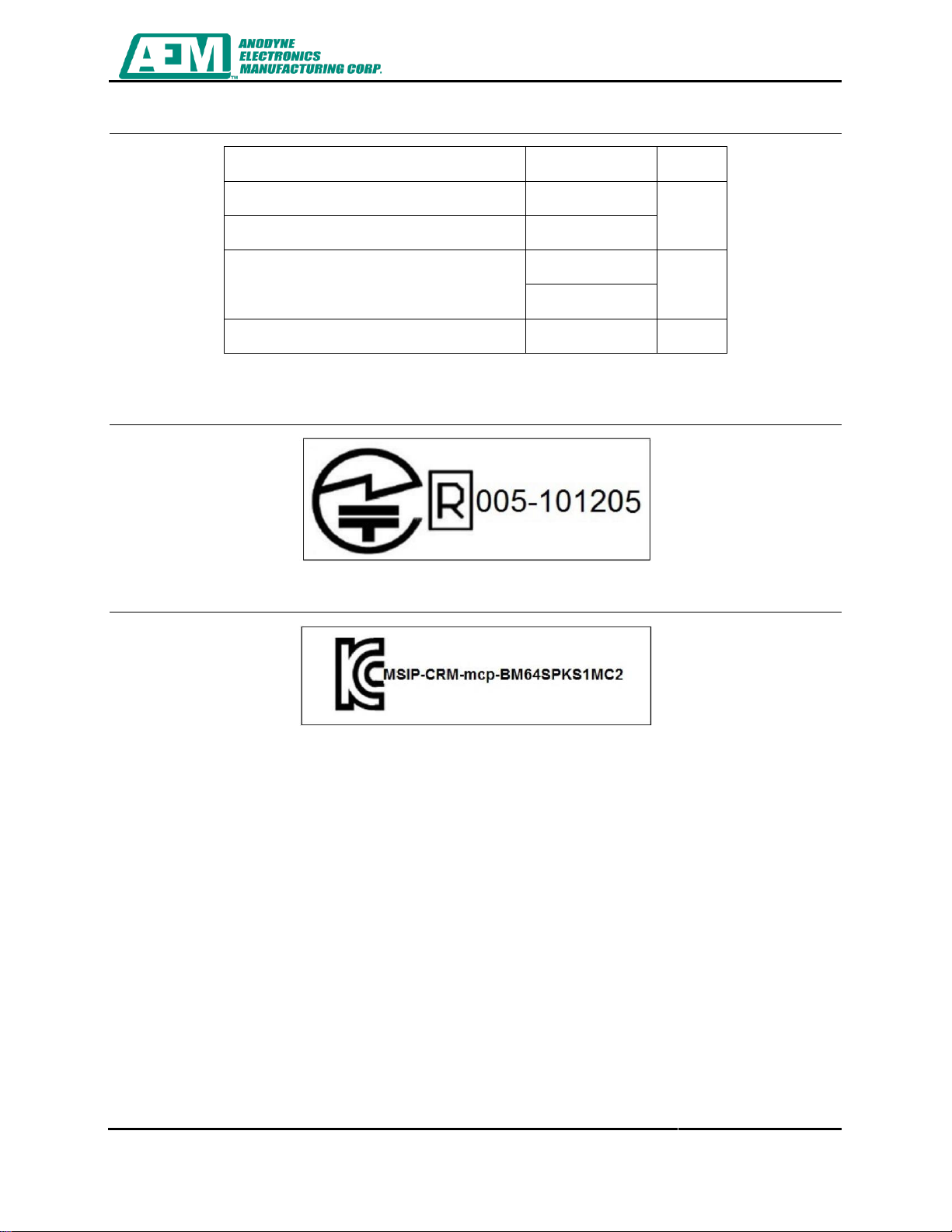
Japan/MIC:
005-101205
1
BAA01 is not qualified to Sec 21.5 Radiated RF, only Sec 21.4 Conducted RF.
2
BAA01 is compliant with the requirements of Fire Protection 14 CFR FAR 23.853.

BAA01-001 Bluetooth Audio Accessory
Installation and Operation Manual
Rev. 1.01 July 25, 2023
Page 6 of 37
ENG-FORM 804-0100.DOTX
CONFIDENTIAL AND PROPRIETARY TO ANODYNE ELECTRONICS MANUFACTURING CORP.
Korea/KCC:
MSIP-CRM-mcp-BM64SPKS1MC2
Taiwan/NCC No:
CCAN16LP0280T8
China/SRRC:
CMIIT ID: 2016DJ2356
Brazil/ANATEL:
03822-18-08759
As per regulatory requirements, the statements in section 1.5.1- 1.5.8 have been
included in this manual.
1.5.1 United States - FCC
Contains FCC ID: A8TBM64S2 This device complies with Part 15 of the FCC Rules.
Operation is subject to the following two conditions: (1) this device may not cause
harmful interference, and (2) this device must accept any interference received,
including interference that may cause undesired operation.
1.5.1.1 Approved Antenna Information
Parameter
Values
Frequency
2400 MHz to 2480 MHz
Peak Gain
1.927 dBi
Efficiency
73.41%
Table 1: BM64 PCB Antenna Characteristics
Parameter
Values
Frequency
2.402 GHz to 2.480 GHz
Receiver Sensitivity
-90 dBm (2 Mbps EDR)
Output Power
+2 dBm typical
Table 2: RF/Analog Characteristics

BAA01-001 Bluetooth Audio Accessory
Installation and Operation Manual
Rev. 1.01 July 25, 2023
Page 7 of 37
ENG-FORM 804-0100.DOTX
CONFIDENTIAL AND PROPRIETARY TO ANODYNE ELECTRONICS MANUFACTURING CORP.
This equipment has been tested and found to comply with the limits for a Class B
digital device, pursuant to part 15 of the FCC Rules. These limits are designed to
provide reasonable protection against harmful interference in a residential installation.
This equipment generates, uses and can radiate radio frequency energy, and if not
installed and used in accordance with the instructions, may cause harmful interference
to radio communications. However, there is no guarantee that interference will not
occur in a particular installation. If this equipment does cause harmful interference to
radio or television reception, which can be determined by turning the equipment off and
on, the user is encouraged to try to correct the interference by one or more of the
following measures:
•Reorient or relocate the receiving antenna
•Increase the separation between the equipment and receiver
•Connect the equipment into an outlet on a circuit different from that to which the
receiver is connected
•Consult the dealer or an experienced radio/TV technician for help
1.5.2 Canada - ISED
This device contains license-exempt transmitters)/receiver(s) that comply with
Innovation, Science and Economic Development Canada’s license-exempt RSS (s).
Operation is subject to the following two conditions:
•This device may not cause interference;
•This device must accept any interference, including interference that may cause
undesired operation of the device.
L’émetteur/récepteur exempt de licence contenu dans le présent appareil est conforme
aux CNR d’Innovation, Sciences et Développement économique Canada applicables
aux appareils radio exempts de licence. L’exploitation est autorisée aux deux
conditions suivantes:
•L’appareil ne doit pas produire de brouillage;
•L’appareil doit accepter tout brouillage radioélectrique subi, même si le brouillage
est susceptible d’en compromettre le fonctionnement.
This radio transmitter [IC: 12246A-BM62S2, IC: 12246A-BM64S1 and IC: 12246A-
BM64S2] has been approved by Innovation, Science and Economic Development
Canada to operate with the antenna types listed in § 1.5.1.1 Approved Antenna
Information with the maximum permissible gain indicated. Antenna types not included
in this list that have a gain greater than the maximum gain indicated for any type listed
are strictly prohibited for use with this device.
Le présent émetteur radio [IC: 12246A-BM62S2, IC: 12246A-BM64S1 and IC: 12246A-
BM64S2] a été approuvé par Innovation, Sciences et Développement économique
Canada pour fonctionner avec les types d'antenne énumérés § 1.5.1.1 Approved
Antenna Information et ayant un gain admissible maximal. Les types d'antenne non
inclus dans cette liste, et dont le gain est supérieur au gain maximal indiqué pour tout
type figurant sur la liste, sont strictement interdits pour l'exploitation de l'émetteur.
BAA01-001 Bluetooth Audio Accessory
Installation and Operation Manual
Rev. 1.01 July 25, 2023
Page 8 of 37
ENG-FORM 804-0100.DOTX
CONFIDENTIAL AND PROPRIETARY TO ANODYNE ELECTRONICS MANUFACTURING CORP.
1.5.3 Europe - CE
Certification
Standards
Article
Safety
EN 62368
3.1a
Health
EN 62311
Electro Magnetic Compatibility (EMC)
EN 301 489-1
3.1b
EN 301 489-17
Radio
EN 300 328
3.2
Table 3: European Compliance
1.5.4 Japan - MIC
1.5.5 Korea - KCC

BAA01-001 Bluetooth Audio Accessory
Installation and Operation Manual
Rev. 1.01 July 25, 2023
Page 9 of 37
ENG-FORM 804-0100.DOTX
CONFIDENTIAL AND PROPRIETARY TO ANODYNE ELECTRONICS MANUFACTURING CORP.
1.5.6 Taiwan - NCC
注意 !
依據 低功率電波輻射性電機管理 ? 法
第十二條 經型式認證合格之低功率射頻電機,非經許 可,
公司、商號或使用者均不得擅自變更頻率、加大功率或 變更原設計
之特性及功能。
第十四條 低功率射頻電機之使用不得影響飛航安全及 干擾合法通信;
經發現有干擾現象時,應立即停用,並改善至無干擾時 方得繼續使用。
前項合法通信,指依電信規定作業之無線電信。
低功率射頻電機須忍受合法通信或工業、科學及醫療用
電波輻射性
電機設備之干擾。
1.5.7 China - SRRC
This device contains SRRC approved Radio module CMIIT ID 2016DJ2356
1.5.8 Brazil - ANATEL

BAA01-001 Bluetooth Audio Accessory
Installation and Operation Manual
Rev. 1.01 July 25, 2023
Page 10 of 37
ENG-FORM 804-0100.DOTX
CONFIDENTIAL AND PROPRIETARY TO ANODYNE ELECTRONICS MANUFACTURING CORP.
1.6 Product Limitations
a) As per FCC regulations stated in Title 47 CRF § 22.925 Prohibition on airborne
operation of cellular telephones:
Cellular telephones installed in or carried aboard airplanes, balloons or any other
type of aircraft must not be operated while such aircraft are airborne (not
touching the ground). When any aircraft leaves the ground, all cellular telephones
on board that aircraft must be turned off. The following notice must be posted on
or near each cellular telephone installed in any aircraft:
“The use of cellular telephones while this aircraft is airborne is prohibited by
FCC rules, and the violation of this rule could result in suspension of service
and/or a fine. The use of cellular telephones while this aircraft is on the ground
is subject to FAA regulations.”
b) Maximum recommended cable length between BAA01 rear charging pins and
connected chargeable device is 4.9 ft [1.5 m].
c) Maximum recommended cable length between BAA01 front panel charging ports
and connected chargeable device is 3.3 ft [1.0 m].
1.7 Product Identifier Description
The product part number is defined as follows:
B
A
A
0
1
-
0
0
1
System Identifier [0-99]:
01: Base System
Major Derivative Identifier [0-9]:
0 = Base System
Minor Derivative Identifier [0-99]:
00: Base System with all functionality enabled.
01: VOX functionality and I/O pins for remote control are unavailable.
Feature Character:
N: NVIS Compatible Lighting.
Blank: No additional features.
End of Section 1.0

BAA01-001 Bluetooth Audio Accessory
Installation and Operation Manual
Rev. 1.01 July 25, 2023
Page 11 of 37
ENG-FORM 804-0100.DOTX
CONFIDENTIAL AND PROPRIETARY TO ANODYNE ELECTRONICS MANUFACTURING CORP.
Section 2.0 Installation
2.1 Introduction
Information in this section consists of unpacking and inspection procedures, installation
procedures, post-installation checks, and installation drawings.
2.2 Unpacking and Inspection
Unpack the equipment carefully. Inspect the unit visually for damage due to shipping
and report all such claims immediately to the carrier involved. Note that each unit
should have the following:
a) BAA01-001
b) Acceptance Test Report
c) Certificate of Conformity or Release Certification
Verify that all items are present before proceeding and report any shortage immediately
to your supplier.
2.3 Installation Configurations
The BAA01 can be interfaced with several audio devices; this document will only
reference common installation use cases between the BAA01 and an audio controller.
These installation cases for section 2.3.1 and 2.3.2. are shown in the interconnect
drawing at the end of this section.
The behaviour of the BAA01 listed in this section is applicable when the BAA01 is in
the Normal mode of operation. For further information specifying the operation of the
BAA01 in different modes of operation, reference Section 3.3 Modes of Operation.

BAA01-001 Bluetooth Audio Accessory
Installation and Operation Manual
Rev. 1.01 July 25, 2023
Page 12 of 37
ENG-FORM 804-0100.DOTX
CONFIDENTIAL AND PROPRIETARY TO ANODYNE ELECTRONICS MANUFACTURING CORP.
2.3.1 BAA01 In-Line between the Headset and Audio Controller
This use case is best suited to be able to select the BAA01 audio directly via the
BAA01 while maintaining headset audio with the audio controller. In this configuration
the BAA01 controls the summed audio of the audio controller and the connected
Bluetooth device. Figure 2: BAA01 In-Line between the Headset and Audio Controller
shows the basic audio routing path in this installation configuration.
Figure 2: BAA01 In-Line between the Headset and Audio Controller
The following statements apply when the BAA01 is installed in this configuration:
a) The BAA01 Bluetooth audio is mixed with the audio from the audio controller and
presented on the headphones.
b) Cellular calls from the connected smart device can be made and accepted.
c) If the audio controller does not have ICS sidetone (artificial sidetone) to the
headsets, the user must use the ART Sidetone Key when speaking on the smart
device phone to hear themselves during cellular calls.

BAA01-001 Bluetooth Audio Accessory
Installation and Operation Manual
Rev. 1.01 July 25, 2023
Page 13 of 37
ENG-FORM 804-0100.DOTX
CONFIDENTIAL AND PROPRIETARY TO ANODYNE ELECTRONICS MANUFACTURING CORP.
2.3.2 BAA01 Installation in a Transceiver Position of the Audio Controller
This use case is best suited when it’s desired to force the selection of a transceiver
position on the audio controller to use the smart device. In this configuration the
Bluetooth audio can only be heard on the headphones if the audio controller is set to
route the Bluetooth audio to the headphones. This can be accomplished with the
transceiver selection or a switched receive selection for listen only. This use case is
best suited when the smart device audio must be controlled by the audio controller.
Each BAA01 user requires a transceiver position. Figure 3: BAA01 in a Transceiver
Position shows the audio routing path in this installation configuration.
Figure 3: BAA01 in a Transceiver Position
The following statements apply when the BAA01 is installed in this configuration:
a) Bluetooth audio is routed to the audio controller.
b) The BAA01 must have a designated position on the audio controller’s selector for
each Bluetooth user.
c) Cellular calls from the connected smart device can be made and accepted.
d) If the audio controller does not have ICS sidetone (artificial sidetone) to the
headsets the user must use the ART Sidetone Key when speaking on the smart
device phone to hear themselves during cellular calls.

BAA01-001 Bluetooth Audio Accessory
Installation and Operation Manual
Rev. 1.01 July 25, 2023
Page 14 of 37
ENG-FORM 804-0100.DOTX
CONFIDENTIAL AND PROPRIETARY TO ANODYNE ELECTRONICS MANUFACTURING CORP.
2.3.3 BAA01 Multi-Unit Installation
When three or more Bluetooth users are required in an aircraft, it is possible to utilize
the in-line between headset and audio controller interface for as many headsets as the
audio controller can support. Figure 4: Multiple BAA01 to Audio Controller shows the
installation configuration where cockpit and cabin headphone users are separated by
using dedicated BAA01 devices.
Figure 4: Multiple BAA01 to Audio Controller
Audio
Controller
PAX 2
PAX 1
Co-Pilot
Pilot

BAA01-001 Bluetooth Audio Accessory
Installation and Operation Manual
Rev. 1.01 July 25, 2023
Page 15 of 37
ENG-FORM 804-0100.DOTX
CONFIDENTIAL AND PROPRIETARY TO ANODYNE ELECTRONICS MANUFACTURING CORP.
2.4 Warranty
Please refer to the standard product warranty conditions available on our website,
www.aem-corp.com
2.5 Installation Procedure
2.5.1 Warnings
WARNING:
High volume settings can cause hearing damage.
Set the headset volume control to the minimum volume setting
prior to conducting tests, and slowly increase the headset
volume to a comfortable listening level.
2.5.2 Cautions
CAUTION:
Verify all airframe connections are checked against the Interconnect
drawing listed in Section 2.10 Installation Drawings
2.5.3 Cabling and Wiring
All wire shall be selected in accordance with the original aircraft manufacturer's
Maintenance Instructions or AC43.13-1B Change 1, Paragraphs 11-76 through 11-78.
Unshielded wire types shall qualify to MIL-W-22759 as specified in AC43.13-1B
Change 1, Paragraphs 11-85, 11-86, and listed in Table 11-11. For shielded wire
applications, use Tefzel MIL-C-27500 shielded wire with solder sleeves (for shield
terminations) to make the most compact and easily terminated interconnect. Follow the
Interconnect drawing in Section 2.10 Installation Drawings as required.
Allow 3" from the end of the shielded wiring to the shield termination to allow the
connector hood to be easily installed. Refer to the Interconnect drawing in Section 2.10
Installation Drawings for shield termination details. Aircraft harnessing shall permit the
unit to be removed for easy access to all adjustments.
Maintain wire segregation and route wiring in accordance with the original aircraft
manufacturers maintenance instructions.
Unless otherwise noted, all wiring shall be a minimum of 24 AWG, except power and
ground lines, which shall be a minimum of 22 AWG. Reference the Interconnect
drawing in Section 2.10 Installation Drawings for additional specifications. Check that
the ground connection is clean and well secured, and that it shares no path with any
electrically noisy aircraft accessories such as blowers, turn and bank instruments or
similar loads.
This manual suits for next models
1
Table of contents


 operating instructions")
