AEM SM28 NTX VHF-FM Series User manual

SPECIAL NOTICE
This product is now licensed to Anodyne Electronics Manufacturing (AEM) from Northern
Airborne Technology (NAT). AEM is responsible for all matters related to this product, including
sales, support and repair services.
Please note the transition to convert product manuals and supporting documentation is an
ongoing process and is being addressed on an ‘as needed’ basis.
All references to NAT product part numbers (and associated images) are equivalent to AEM
product part numbers.
Contact info:
Anodyne Electronics Manufacturing Corp.
#15-1925 Kirschner Road
Kelowna B.C. Canada
V1Y 4N7
Email: support@aem-corp.com
Toll Free: 1-888-763-1088
Phone: 1-250-763-1088
Fax: 1-250-763-1089
www.aem-corp.com
CONFIDENTIAL AND PROPRIETARY TO ANODYNE ELECTRONICS MANUFACTURING CORP.
INSTALLATION AND OPERATION MANUAL
REV 5.00 May 9, 2012
Anodyne Electronics Manufacturing Corp.
15-1925 Kirschner Road
Kelowna, BC, Canada.
V1Y 4N7
Telephone (250) 763-1088
Facsimile (250) 763-1089
Website: www.aem-corp.com
© 2012 Anodyne Electronics Manufacturing Corp. (AEM),
All Rights Reserved
SM28
NTX VHF-FM Series
Remote Mount Transceivers

NTX VHF FM Series Remote Mount Transceiver
SM28 Installation and Operation Manual
Installation and Operation Manual Page ii
ENG-FORM: 820-0100.DOTX
CONFIDENTIAL AND PROPRIETARY TO ANODYNE ELECTRONICS MANUFACTURING CORP.
IMPORTANT INFORMATION
FOR AVIONICS INSTALLATION
FACILITIES
The NTX VHF-FM Series Remote Mount Transceivers are supplied
without TSO certification, as no such standard presently exists for
airborne VHF-FM radio transceivers. This equipment provides
what is considered as 'supplemental' communications, and can be
installed in an aircraft on a 'Non interference' basis. Installation
should be performed using standard procedures applicable to
aircraft radio installation, to ensure that the newly installed
equipment does not interfere with any other equipment in the
aircraft.
This device complies with Part 15 of the FCC Rules. Operation is
subject to the condition that this device does not cause harmful
interference.
COPYRIGHT STATEMENT
© 2012 Anodyne Electronics Manufacturing Corp. (AEM), All Rights Reserved
This publication is the property of AEM and is protected by Canadian copyright laws.
No part of this document may be reproduced or transmitted in any form or by any
means including electronic, mechanical, photocopying, recording, or otherwise, without
the prior written permission of AEM.

NTX VHF FM Series Remote Mount Transceiver
SM28 Installation and Operation Manual
Installation and Operation Manual Page iii
ENG-FORM: 820-0100.DOTX
CONFIDENTIAL AND PROPRIETARY TO ANODYNE ELECTRONICS MANUFACTURING CORP.
Prepared By:
Checked By:
Approved By:
The status of this installation and operation manual is controlled by the revision shown on the title page.
The status of each section is controlled by revision shown in the footer of each page. All revisions
affecting sections of this manual have been incorporated.
AEM MANUAL REVISIONS
Section
Revision Number
Revision Description
Date
All
Rev: 5.00
Updated drawings and template
May 9, 2012
Tony Pearson
Designer
May 9, 2012
Loen Clement
Designer
Jun 11/12
Tom Betzelt
Product Support
Manager
June 11, 2012

NTX VHF FM Series Remote Mount Transceiver
SM28 Installation and Operation Manual
Installation and Operation Manual Page iv
ENG-FORM: 820-0100.DOTX
CONFIDENTIAL AND PROPRIETARY TO ANODYNE ELECTRONICS MANUFACTURING CORP.
Table of Contents
Section Title Page
1.0 Description
1.1 Introduction 1-1
1.2 Purpose of Equipment 1-1
1.3 Features 1-1
1.4 Specifications 1-2
1.4.1 Electrical Specifications 1-2
1.4.2 Receiver 1-2
1.4.3 Transmitter 1-3
1.4.4 Physical Specifications 1-3
1.4.5 Environmental Specifications 1-3
1.5 VHF-FM Radio Spurious Frequencies 1-4
1.6 Unit Nomenclature 1-4
2.0 Installation
2.1 Introduction 2-1
2.2 Unpacking and Inspection 2-1
2.2.1 Warranty 2-1
2.3 Installation Procedures 2-1
2.3.1 Warnings 2-1
2.3.2 Cautions 2-1
2.3.3 Notes 2-1
2.3.4 Cabling and Wiring 2-2
2.3.5 Antennas 2-3
2.3.6 Mechanical Mounting 2-3
2.3.7 Post-Installation Checks 2-4
2.3.8 Post-Installation EMI Test 2-4
2.4 Continued Airworthiness 2-5
2.5 Installation Drawings 2-5
3.0 Operation
3.1 Introduction 3-1
3.2 General 3-1
3.3 Configuration 3-1

NTX VHF FM Series Remote Mount Transceiver
SM28 Installation and Operation Manual
May 9, 2012 Rev: 5.00 Page 1-1
ENG-FORM: 800-0100.DOTX
CONFIDENTIAL AND PROPRIETARY TO ANODYNE ELECTRONICS MANUFACTURING CORP.
Section 1.0 Description
1.1 Introduction
This manual contains information on the NTX066 and NTX138 Remote Mount VHF-FM Series Remote
Mount Transceivers. All derivative products will be covered by manual supplements, which can be
obtained from AEM as required. Information in this section consists of equipment, features and
specifications.
1.2 Product Description
The NTX VHF-FM Series Remote Mount Transceivers are mounted using a custom ¼ ATR tray and are
operated using an AEM Tac/Com™control head. The NTX066 models operate over 66 to 88 MHz on the
VHF mid-band, and the NTX138 models are capable of receiving and transmitting over 138 MHz to 174 MHz
on the VHF high band.
Primaryapplications include airborne Search and Rescue, Law Enforcement and Forestry communications.
1.3 Features
The existing Tac/Com™series of control heads provide control for the transceivers.
The NTX066 range is 66.0000 to 87.9975 MHz, and the NTX138 VHF-FM models cover a frequency
range of 138.0000 –173.9975 MHz, both in 2.5 kHz increments. A maximum of 200 channels are
available depending on the type of control head used. Depending on the model selected, the channels
can include a receive frequency and CTCSS or DCS tone, transmit frequency and CTCSS or DCS tone,
and an alphanumeric identifier.
Depending on the model selected, the transceiver provides wideband or narrowband receiver selectivity
(selectable by the control head). Wideband operation provides a bandwidth of 25 kHz and narrowband
operation provides a bandwidth of 12.5 kHz.
The NTX138 transceiver can also be selected with an optional guard receiver installed or a DF
compatible output signal. The NTX138-100 provides a DF compatible output signal.
Voice Inversion Scrambling is available as an option, depending on the selected model.
A scan function allows scanning of selected channels. Transmit power of either 1 watt or 10 watts is
selectable from the control head. Simplex and semi-duplex operations are available. DTMF encoding
and direct keyboard programming can be added using AEM’s DTE12.

NTX VHF FM Series Remote Mount Transceiver
SM28 Installation and Operation Manual
May 9, 2012 Rev: 5.00 Page 1-2
ENG-FORM: 800-0100.DOTX
CONFIDENTIAL AND PROPRIETARY TO ANODYNE ELECTRONICS MANUFACTURING CORP.
1.4 Specifications
1.4.1 Electrical Specifications
Input Power 28 Vdc Power
Current consumption
NTX066 and NTX138 models 300 mA receive / 2.5 A transmit (typical)
500 mA receive / 3.0 A transmit (max.)
Sidetone output
NTX066 and NTX138 models 25 mW @ 600 Ωnominal
Microphone
NTX066 and NTX138 models Amplified dynamic or equivalent, 150 Ω
balanced/unbalanced
Scrambling 3.1 kHz Voice Inversion
(Optional on NTX138 and NTX066 models)
Frequency range
NTX066 models 66.0 MHz to 87.9975 MHz
NTX138 models 138.000 MHz to 173.9975 MHz
Tone Capability 38 EIA standard CTCSS tones 70 DCS tones
Operating mode F3E simplex or semi-duplex
1.4.2 Receiver
Chanel increments 2.5 kHz
Audio output
NTX066 and NTX138 models 100 mW into 600 Ω, nominal
Sensitivity
NTX066-000 0.50 μV @ 12 dB SINAD
NTX138-050 Main 0.50 μV @ 12 dB SINAD
Guard 0.50 μV @ 12 dB SINAD
NTX138-000 0.35 μV @ 12 dB SINAD
NTX138-100 Main 0.35 μV @ 12 dB SINAD
DF 1.0 μV @ 12 dB SINAD
Selectivity -70 dB min. @ 25 kHz (Wideband)
-60 dB min. @ 12.5 kHz (Narrowband)
Spurious response -70 dB
Intermodulation -70 dB

NTX VHF FM Series Remote Mount Transceiver
SM28 Installation and Operation Manual
May 9, 2012 Rev: 5.00 Page 1-3
ENG-FORM: 800-0100.DOTX
CONFIDENTIAL AND PROPRIETARY TO ANODYNE ELECTRONICS MANUFACTURING CORP.
1.4.3 Transmitter
RF power output 1 W/10 W selectable
RF output impedance 50 Ωnominal
Modulation
Wide band ±5.0 kHz max. Limited
Narrow band ±2.5 kHz max, limited
Output spurious -65 dB
Frequency stability ±0.0003%
FM noise -45 dB
Distortion <5% nominal, 10% max
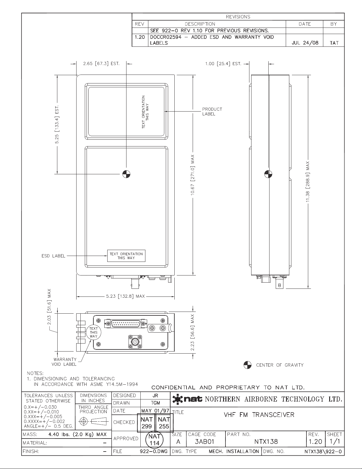
1.4.4 Physical Specifications
Height 2.21" (56.1 mm)
Overall length 11.38" (289.1 mm)
Length without connector 10.67” (271.1 mm)
Width 5.23" (271.2 mm)
Weight 4.0 lbs (1.8 kg)
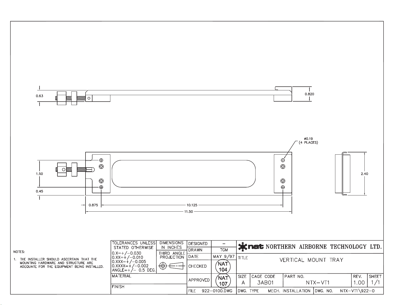
Mounting Custom AEM ¼ ATR tray (NTX-VT1)
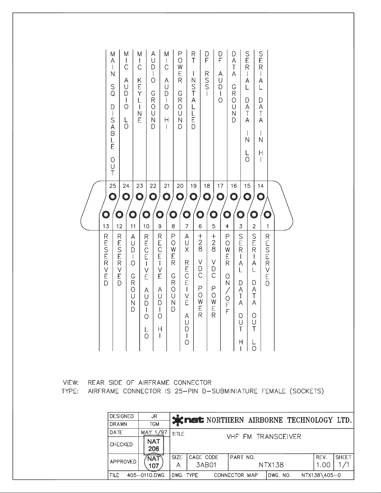
Connector type Male filtered 25-pin D-subminiature with
Positronics V5 locking tabs
Antenna Connector Bulkhead female BNC
1.4.5 Environmental Specifications
Temperature: -30C. to +60C
Altitude 25,000 feet
Humidity 95%
Shock 12 g (any axis)
Environmental conformance: DO-160C Env. Cat. B4-BA[MN]XXXXXXAB[AB]BAUAXXX

NTX VHF FM Series Remote Mount Transceiver
SM28 Installation and Operation Manual
May 9, 2012 Rev: 5.00 Page 1-4
ENG-FORM: 800-0100.DOTX
CONFIDENTIAL AND PROPRIETARY TO ANODYNE ELECTRONICS MANUFACTURING CORP.
1.5 VHF-FM Radio Spurious Frequencies
All VHF-FM radios are subject to the reception of spurious signals. Avoid operation on these frequencies
whenever possible.
The frequencies affected within the NTX066 radio are 66.00 MHz, 72.00 MHz, and 84.00 MHz.
The frequencies affected within the NTX138 radios are 138.000 MHz, 144.00 MHz, 156.00 MHz and
168.000 MHz.
1.6 Unit Nomenclature
Model Description / Distinction
NTX066-000
66.0 MHz –88.0 MHz VHF-FM transceiver.
200 channel memory
38 CTCSS tones
70 DCS tones
1 W or 10 W selectable.
List, Priority or List+Priority scanning.
Optional Voice Inversion Scrambling
NTX138-000
138 MHz –174 MHz VHF-FM transceiver.
200 channel memory
38 CTCSS tones
70 DCS tones
1 W or 10 W selectable.
List, Priority or List+Priority scanning.
Optional Voice Inversion Scrambling
NTX138-050
138 MHz –174 MHz VHF-FM transceiver.
200 channel memory
38 CTCSS tones
70 DCS tones
1 W or 10 W selectable.
List, Priority or List+Priority scanning.
2 channel crystal controlled USFS guard receiver.
Optional Voice Inversion Scrambling
NTX138-100
138 MHz –174 MHz VHF-FM transceiver.
200 channel memory
38 CTCSS tones
70 DCS tones
1 W or 10 W selectable.
List, Priority or List+Priority scanning.
DF compatible output signal
Optional Voice Inversion Scrambling
End of Section 1.0

NTX VHF FM Series Remote Mount Transceiver
SM28 Installation and Operation Manual
May 9, 2012 Rev: 5.00 Page 2-1
ENG-FORM: 805-0100.DOTX
CONFIDENTIAL AND PROPRIETARY TO ANODYNE ELECTRONICS MANUFACTURING CORP.
Section 2.0 Installation
2.1 Introduction
Information in this section consists of: unpacking and inspection procedures, installation procedures,
post-installation checks, and installation drawings.
2.2 Unpacking and Inspection
Unpack the equipment carefully. Inspect the unit visually for damage due to shipping and report all such
claims immediately to the carrier involved. Note that each unit should have the following:
- NTX VHF FM Series Remote Mount Transceiver
- Product Information Card
- Release certification
Verify that all items are present before proceeding and report any shortage immediately to your supplier.
2.2.1 Warranty
All Anodyne Electronics Manufacturing Corp. (AEM) products are warranted for 2 years. See the website
www.aem-corp.com/warranty for complete details.
2.3 Installation Procedures
2.3.1 Warnings
Do not bundle any lines from this unit with transmitter coax lines. Do not bundle any logic, audio, or DC
power lines from this unit with 400 Hz synchro wiring or AC power lines. Do not position this unit next to
any device with a strong alternating magnetic field such as an inverter or significant interference to
operation will result. In all installations, use shielded cable exactly as shown and ground as
indicated. Significant problems may result if these guidelines are not followed.
2.3.2 Cautions
Severe degradation of audio installations may result from incorrect wiring and shielding. This could
cause much higher cross-talk, hum, and ground-loop interference.
2.3.3 Notes
For maximum resistance to low frequency interference, electrically ground the case of the
transceiver.

NTX VHF FM Series Remote Mount Transceiver
SM28 Installation and Operation Manual
May 9, 2012 Rev: 5.00 Page 2-2
ENG-FORM: 805-0100.DOTX
CONFIDENTIAL AND PROPRIETARY TO ANODYNE ELECTRONICS MANUFACTURING CORP.
2.3.4 Cabling and Wiring
All unshielded wire shall be selected in accordance with the original aircraft manufacturer’s maintenance
instructions or AC43.13-1B Change 1, Paragraphs 11-76 through 11-78. Wire types should be to MIL-W-
22759 as specified in AC43.13-1B Change 1, Paragraphs 11-85, 11-86, and listed in Table 11-11. For
shielded wire applications, use Tefzel MIL-C-27500 shielded wire with solder sleeves (for shield
terminations) to make the most compact and easily terminated interconnect. Follow the wiring diagrams
in Section 2.5 as required.
To provide easy installation of the hood, allow 3 inches from the end of the wire to the shield termination.
Note: Install the hood after the wiring is complete.
Installation cabling must allow the transceiver to be easily withdrawn for disconnection and field service
adjustments. Ensure an adequate service loop in the routing of the cables.
All wiring should be 22 AWG, except power and ground connections, which must be 18 AWG or
larger, as indicated on the installation drawings. Ensure that the ground connection is clean and well
secured. To prevent inadvertent system failure, supply power to this system from a separate breaker or
fuse not connected to any other device. NAT recommends a 5 A fuse or breaker (28 Vdc Source).
Coaxial cable should be in accordance with MIL-C-17 unless otherwise specified. Do not use coax
with PVC insulation. NAT recommends Teflon dielectric cable at or above VHF frequencies or where
cable runs exceed 8 feet. Note that at VHF frequencies, cable losses due to long cable runs and tight
bends may cut the ERP (Effective Radiated Power) to less than 50% of specification.
To prevent RF interference between similar systems, NAT recommends that VHF FM coax runs be
widely separated, or be made using triaxial cable. Bond the outer shield to the airframe at the transceiver
end only.
In communication intensive applications, bad cable routing and shielding may drastically compromise
over-all system performance. Symptoms will be spurious squelch opening, RFI (Radio-Frequency
Interference), and garbled reception.
Neatly terminate RF cables (solder or crimp) and test for shorts prior to system check- out (not while
connected to the radio!!). Keep cable bends to a minimum at the antenna.
Avoid sharp bends in the coax cables (minimum 3" radius) to prevent severe reflections. If sharp bends
are required use 90° elbow adapters.
Fabrication and installation of wiring harness should be in accordance with the original aircraft
manufacturer’s maintenance instructions or AC43.13-1B Change 1, chapter 11, sections 5 to 13, 16 and
17.
Grounding and bonding should be in accordance with the original aircraft manufacturer’s maintenance
instructions or AC43.13-1B Change 1, chapter 11, section 15.

NTX VHF FM Series Remote Mount Transceiver
SM28 Installation and Operation Manual
May 9, 2012 Rev: 5.00 Page 2-3
ENG-FORM: 805-0100.DOTX
CONFIDENTIAL AND PROPRIETARY TO ANODYNE ELECTRONICS MANUFACTURING CORP.
2.3.5 Antennas
Correct antenna placement and mounting is critical in order to achieve the best possible performance. In
general, keep all antennas as widely separated as possible and clear of any large airframe obstructions.
Avoid any placement that puts antennas of like frequencies close together.
Installation of the antenna should be in accordance with the aircraft manufacturer’s instructions for
continued airworthiness or AC43.13-1B Change 1, chapter 11, section 15 and AC 43.13-2A chapter 3.
If possible, the antenna should be located a minimum of 12 ft from aircraft navigation receiver antennas
and a minimum of 4 ft from aircraft communications and ELT antennas. Be careful not to choose
separations that closely approximate ¼, ½ or whole number multiples of the navigation or communication
system wavelengths.
Bottom mounted antennas will perform best in flight, but poorest on the ground during testing. Antennas
may be severely degraded by 'masking' effects of the fuselage or stabilizers, and generally give best
performance when bottom mounted.
Surround any blade or whip antenna with a ground plane surface (metallic, grounded material) having a
radius equal to or greater than the height of the antenna. Poor grounding will result in severe reflected
power and high levels of RFI throughout the airframe.
Any antenna will be less prone to interference from rotor modulation and other undesirable stimuli if installed
correctly and surrounded by a large metallic ground plane. Under the same conditions, it is also much less
likely to cause interference to other aircraft systems (e.g., coupling into audio system, fluctuations in
instrumentation, etc.). Poor grounding will result in severe reflected power and high levels of RFI throughout
the airframe.
Avoid antenna locations that will become fouled with oil, water, fuel or dirt as this will degrade
performance. Roof mounts (in close proximity to rotor blades) are permissible.
2.3.6 Mechanical Mounting
Installation of the transceiver should be in accordance with the aircraft manufacturer’s instructions for
continued airworthiness or AC 43.13-1B Change 1, chapter 7, sections 2 to 7, and AC 43.13-2A chapter
2.
The transceiver is tray-mounted and uses a custom 1/4 ATR style tray. Mount (with countersunk
screws) onto a clean, grounded surface having a resistance of less than 0.5 ohms to airframe ground.
The transceiver may be mounted in any attitude, but upright (mounting hook at the bottom) is
preferred for access and condensation drainage.

NTX VHF FM Series Remote Mount Transceiver
SM28 Installation and Operation Manual
May 9, 2012 Rev: 5.00 Page 2-4
ENG-FORM: 805-0100.DOTX
CONFIDENTIAL AND PROPRIETARY TO ANODYNE ELECTRONICS MANUFACTURING CORP.
2.3.7 Post-Installation Checks
2.3.7.1 Voltage/Resistance Checks
Do not attach the
transceiver
until the
following conditions
are
met.
Check the following:
a) P101 pins <5> and <6> for +28 Vdc relative to ground.
b) P101 pins <8> and <20> for continuity to ground (below 0.5 Ω).
Ensure that the antenna is
disconnected
for the
following
test or
erroneous
readings may be
obtained.
c) Radio coax connector for continuity to the antenna coax connector (shield and center
conductor) and for open circuit from the center conductor to ground and open circuit from the
center conductor to the shield.
2.3.7.2 Power On Checks
a) Install the transceiver and power up the ship’s systems. Turn on the control head.
Check the operation of all front panel controls. Adjust brightness and volume levels as
required.
b) Check all transmit and receive functions. Ensure the RX/TX status indicator lights green when
keying the radio to transmit and amber when receiving.
c) Check the SCAN function.
Note: You may be unable to hear the received audio if the tones do not match those set in the radio.
To avoid any confusion, set the tones to OFF (via the Status Edit mode) during scanning so
that all channels will be heard.
d) Check the antenna feedline at the R/T with a through-line wattmeter and suitable frequency
elements to ensure correct antenna matching. Reflected power in excess of 25% represents a
serious problem, and should be investigated carefully, or serious RFI and system interference as
well as possible radio damage may result. A VSWR measurement over 3.0:1 represents a
significant loss in signal power to the antenna. Check that forward power is to specifications over
the frequency band of the radio.
2.3.8 Post-Installation EMI Tests
The purpose of this test is to identify any interference that the transceiver may cause with existing
aircraft systems. The transceiver should be tested in accordance with the Installation Approval Test
Procedure (see section 2.5) and the test results documented on the record sheets.

NTX VHF FM Series Remote Mount Transceiver
SM28 Installation and Operation Manual
May 9, 2012 Rev: 5.00 Page 2-5
ENG-FORM: 805-0100.DOTX
CONFIDENTIAL AND PROPRIETARY TO ANODYNE ELECTRONICS MANUFACTURING CORP.
2.4 Continued Airworthiness
Maintenance of the NTX VHF-FM Series Remote Mount Transceiver is ‘on condition’ only. Periodic
maintenance of these products is not required.
2.5 Installation Drawings
DOCUMENT
REV.
DESCRIPTION
TYPE
NTX138\403-0
1.30
Remote Mount Radio
Interconnect
NTX138\405-0
1.00
Remote Mount Radio
Connector Map
NTX138\922-0
1.20
Remote Mount Radio
Mechanical
NTX-VT1\922-0
1.00
Vertical Mount Tray
Mechanical
NTX138\634-0
1.00
Post-Installation EMI Test
Installation Approval Test Procedure
NTX066\634-0
1.00
Post-Installation EMI Test
Installation Approval Test Procedure
Section 2.0 ends following above documents


INSTALLATION APPROVAL
TEST PROCEDURE
NAT Part #: NTX138 Description: Remote Mount FM Transceivers
Document #: NTX138\634-0 Rev: 1.00
Rev. 1.00 Aug 31, 2001 Page 1 of 7
ENG-FORM: 634-0100.DOT
CONFIDENTIAL AND PROPRIETARY TO NORTHERN AIRBORNE TECHNOLOGY LTD.
1. Post Installation EMI Test
The purpose of this test is to identify any interference that the NTX138 may cause with
existing aircraft systems.
2. Test Conditions
The NTX138 should be installed and function tested. The antenna VSWR should be
checked. A forward/reverse power check with an in-line wattmeter should show no
more than 10% reflected power. For the following tests, insure that the transmit power
is set to HI.
3. Methodology
Most of the EMI tests can be accomplished on the ground. In some cases, flight testing is
required or is easier. If the aircraft is approved for IFR operations, then it is mandatory
that interference between the NTX138 and the approach aids be checked in flight.
The GPS should be operational and navigating with at least the minimum compliment of
satellites. The VHF comm should be set to the frequencies indicated with the squelch open.
VOR/ILS/GS receivers should be set to the frequencies indicated and selected for display. If
possible, set up a VOR/ILS ramp test set on the frequencies indicated and adjust the output
until the flags are out of view. The transponder and encoder should be monitored with ramp
test equipment. If possible set the ADF to a nearby navigation station.
Modulate the NTX138 transmitter on the indicated frequencies for at least 20 seconds.
Observe the GPS for any degradation in satellite status or availability or flags. Listen for
any noise or detected audio signals on the VHF comm(s). Listen for any noise or
detected audio signals on the VOR/LOC receiver audio; look for any movement of flags
or needles on the VOR/LOC/GS navigation display(s).
List the power plant, fuel and other electric instruments in the chart provided and note
any anomalies that occur while transmitting. Assess the results.
If the aircraft is equipped with an autopilot or a stability augmentation system, then test
fly the aircraft and verify that the operation of the NTX138 transceiver does not have
adverse effects on these systems. After checking for gross effects at a safe altitude, fly
an approach with each of the different navigation systems coupled to the autopilot (ILS,
GPS etc.) and look for any anomalies.
NTX138 Installation Approval Test Procedure
Page 2 of 7 Aug 31, 2001 Rev. 1.00
E NG-FORM: 634-0100.DOT
CONFIDENTIAL AND PROPRIETARY TO NORTHERN AIRBORNE TECHNOLOGY LTD.
4. Results
If the installed system passes all of the applicable EMI tests, then no further action is
required. If interference is observed, then the interference must be assessed against
the appropriate standards of airworthiness for the system in question. For example: it is
permissible for a VFR certified GPS to lose navigation capability while the NTX138 is
transmitting, providing that it recovers properly and promptly, but it is not permissible for
an IFR Approach certified GPS to be affected in the same way. A complete discussion
of all the standards of airworthiness to be applied in assessing EMI effects is beyond
the scope of this document.
5. Procedure
A. Operate the NTX138 transmitter on the following frequencies for at least 20 seconds.
Observe the GPS for any degradation in satellite status, or availability, or flags.
FREQUENCIES GPS #1 GPS #2
NTX138 PASS FAIL PASS FAIL
143.180 MHz
143.1825 MHz
157.5000 MHz
157.5425 MHz
NOTES:
This manual suits for next models
1
Table of contents


