manuals.online logo
Brands
  1. Home
  2. •
  3. Brands
  4. •
  5. Kenwood
  6. •
  7. Transceiver
  8. •
  9. Kenwood TR-9130 User manual

Kenwood TR-9130 User manual

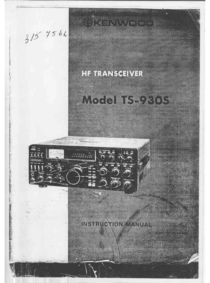
@KENWOOD
SERVICE
MANUAL
TR-9130
2m
ALL
MODE
TRANSCEIVER
TRANSCEIVER
if
2
TONE
ES
CTS
CONTENTS
CIRCUIT
DESCRIPTION
......c.ccccccccscsesesssessseeseeseeseeeeseeesees
2
RX
Unit
(X55-1320-00,11)
.o.ccccccccseceseeeseeeseeneeeeees
21
PARTS
Ut
STisshvesiesivceccestacrtian
mien
iia
aueed
actndeveoeny:
8
CAR
Unit
(X50-1870-11,51,61)
...ccccccceesseeseeeeteeneees
22
PACKING
5s
7
ocd
del
tai
itaienhitd
aan
an
aecnind
14
Control
Unit
(X53-1210-11,62)
...cccccccccesseeeeeeereees
22
DISASSEMBLYisk.ccoiitacianietiiee
tenth
nelle
15
ADJUSTMENTS
o.oo
ccccsecescscesecsssesestsesseeeeeeeneenseereeeees
24
PC
BOARD
VIEWS
LEVEL
DIAGRAM
jis.
ccciedtevceiccrheticuieciecdtte
Basics
31
Switch
Unit
(X41-1400-14)
oo
cecccccccsseeeseeeeeeeeeees
18
BLOCK
DIAGRAM
cicscdesdsdscscsctssesssdivavsdebiecsstllentiulayessoin’s
32
Final
Unit
(X45-1240-11)
oo.
cccccccecescceseseseseseseeeteees
18
SCHEMATIC
DIAGRAM............05+
ths
ORC
selected
ae
ret aee
33
Drive
Unit
(X47-1090-11,61).....cccccccecceceeseeeeeeterees
19
REFERENCE
DATA
i
iscssisesepstivsestes
tseetiiceadead
opened
sci
eetdiee:
35
PLL
Unit
(X50-1
860-00)
oo...
.eeccccccecseeceeecesseeeeeeeeeeees
20
SPECIFICATIONS.......ccccccssscscssesesessssessseeee
seers
BACK
COVER
at
i
ee
Se
a
ee
TR-9130
CIRCUIT
DESCRIPTION
Receiver
Circuit
Configuration
The
front
end
employs
a
dual
gate
MOS
FET
Q1:3SK76
and
a
helical
resonator,
L3.
The
first
mixer
(Q2:
3SK74},
followed
by
a
2-stage
MCF
(Monolithic
Crystal
Filter)
XF1,
provides
excellent
two-signal
characteri-
stics
and
high
sensitivity.
The
IF
signal
from
the
MCF
is
applied
to
both
SSB
and
FM
circuits.
The
SSB
signal,
having
passed
through
the
NB
(Noise
Blanker)
D7,
D8
gate
and
crystal
filter
XF2
(10H2.2SD)
is
amplified
by
IF
amplifiers
Q11
-
Q13
and
demodulated
into
an
audio
signal
by
the
product
detector
D10
~
D13.
In
the
NB
circuit,
the
signal
from
the
MCF
XFI
is
differential
by
O3
and
Q4
and
is
then
applied
to
the
second
mixer,
Q5.
The
noise
signal,
converted
to
a
455kHz
signal,
is
limited
by
D2,
D3,
two-stage
amplified
by
Q7,
Q8
rectified
by
D4,
D5,
and
operates
the
NB
gate
through
Q10,
a
switch
transistor.
9
is
the
N.B.
AGC
ampli-
fier.
The
NB
on/off
control
is
located
on
the
front
panel.
The
AGC
picks
up
the
signal
from
the
IF
final
stage
Q13,
amplifies
the
signal
by
014,
rectifies
this
by
D14,
D15.
itis
then
DC
amplified
by
Q15,
and
the
AGC
voltage
is
applied
to
the
three
stages
of
IF
amplifier
Q11
-
Q13:
3SK73
and
the
RF
amplifier
Q1:
3SK76.
It
is
also
used
to
drive
the
meter.
Q17
is
the
signal
meter
amplifier,
Q18
is
the
meter
driver.
The
time
constant
is
automatically
select-
ed
according
to
the
mode
by
016,
D16:
FAST
for
CW
and
SLOW
for
SSB.
The
SSB
squelch
is
a
noise
type
utilizing
an
FM
squelch
circuit.
The
SSB
IF
signal
is
picked
up
from
the
AGC
buffer
amplifier
Q14,
amplified
by
Q19,
and
converted
to a
455kHz
signal
by
O20.
This
signal
is
applied
to
the
FM
IF
amplifier,
effecting
squelch
on/off
operation
according
to
the
noise
level
component
above
the
normal
3kHz
limit
needed
for
voice
communication
in
the
same
manner
as
the
FM
squelch
operates.
Thus,
in
SSB
mode,
the
FM
IF
ampli-
fier
is
also
operated
by
this
signal.
The
squelch
on/off
timing
is
controlled
by
Q29
~
Q30
and
C120.
The
scan
stop
signal
for
both
SSB
and
FM
is
sent
to
the
microprocessor.
In
the
FM
circuit,
the
signal,
having
passed
through
the
ceramic
filter
CFl
CFW-455F
(K/M
type)
or
CFW-455E
(W/T
type),
is
amplified
by
IF
amplifiers
Q21:
TA7O60,
Q22-23:
2SC1675(L),
Limiter
amplifiers
024,
25:
2SC1675(L),
then
detected
by
ceramic
discriminator
L30
and
diodes
D27,
28.
In
all
modes,
the
detected
AF
signal
is
amplified
by
Q35:
25C1815(Y),
passed
through
the
active
LPF
Q36:
25C1815(Y)
AF
GAIN
controlled,
and
power
amplified
by
038:
MB3713
to
drive
the
speaker.
fe
ee
Fig.
1
MB3713
Enulvelene:
circuit
(RX
unit
Q38)
CFW455F
455
kHz
CFW455E
Nominal
center
frequency
6
dB
bandwidth
+
7.5
kHz
or
more
+6
kHz
or
more
50
dB
bandwidth
+15
kHz
or
less
+12.5
kHz
or
more
Ripple
(within
455
+5
kHz)
3 dB
or
jess
3
dB
or
less
6
dB
or
less
6
dB
or
less
Guaranteed
attenuation
(within
455
+
100
kHz)
Saab
ornare
Input
and
output
impedance
1.5
kQ
2.0
kQ
35 dB
or
more
Table
1.
Ceramic
filter
(L72-0315-05)
CFW455F
(K,M-type)
(L72-0316-05)
CFW455E
(W,T-type)
(RX
Unit
:
CF1)
+1.5
kHzor
less
at
20
dB
+2.4
kHz
or
less
at
60
dB
Attenuation
bandwidth
Less
than
2
dB
Less
than
5
dB
60
dB
or
more
within
+40
kHz
Guaranteed
attenuation
6002
+
10%/15
pF
+10%
Input
and
output
impedance
Table
2.
Crystal
filter
(L71-0215-05)
10H2.2SD
(RX
Unit
:
XF2)
Rating
—+
Nominal
center
frequency
(fo)
10.695
MHz
Pass
bandwidth
+7.5
kHz
or
more
at
3
dB
+25
kHz
or
less
at
40
dB
+45
kHz
or
less
at
60
dB
Attenuation
bandwidth
.
70 dB
or
more
within
+1
MHz
2.
Spurious
level
=
40
dB
or
more
at
fo
~
fo
+500
kHz
3.
Spurious
level
=
80
dB
or
more
at
fo
—
(910
kHz
+10
kHz)
Guaranteed
attenuation
1.0
dB
orless
Loss
1.5
dB
or
less
Impedance
3
k2/0
pF
Table
3.
MCF
(L71-0216-05)
(RX
Unit
:
XF1)
:
TR-9130
CIRCUIT
DESCRIPTION
Transmitter
Circuit
Configuration
The
signal
from
the
microphone
is
amplified
by
Q1:
2SC2240(GR)
which
is
common
to
both
SSB
and
FM
circuits.
The
SSB
signal
is
fed
to
the
RX
unit,
where
it
first
passes
through
the
SSB
MIC
GAIN
trimmer
VR5
is
two-
stage
amplified
by
Q39
-
40:
25C1815(Y),
and
then
enters
the
balanced
modulator
D389
~
D42
together
with
the
carrier
(10.695MHz)
amplified
by
Q41.
The
modulator
is
balanced
by
VR7
and
TC2,
for
minimum
unwanted
carrier
in
SSB.
The
resulting
DSB
signal
from
the
modulator
is
buffer
amplifier
by
Q42:
2SK61(GR)
and
is
converted
to
an
SSB
signal
after
passing
through
the
crystal
filter.
After
one
stage
of
amplification
by
044,
this
is
applied
to
the
trans-
mitter
balanced
mixer
Q5
—
6:
2SK61(GR)
on
the
TX
unit.
In
the
FM
mode,
the
audio
signal
from
the
first
mic
amplifier
Q1
is
limiter-amplified
by
Q2:
TA7O61AP,
then
directly
modulates
the
crystal
oscillator
(L2)
output
at
10.695
MHz
Q3
is
the
Oscillator,
and
Q4
an
emitter
follower.
Audio
is
applied
to
varactor
diode
D1:
1S2208.
The
subsequent
circuit
configuration
is
common
in
all
modes.
The
signal,
having
passed
through
the
TX
mixer
Q5,
O6
is
band-pass
filtered
to
remove
the
unwanted
spurious
Signal
component.
The
BPF
is
tuned
by
varactor
diodes
D3
~
D6,
con-
trolled
by
the
PLL
(phase-locked
loop)
VCO
(voltage-
controlled
oscillator)
correction
voltage.
The BPF
output
is
amplified
by
Q7:
3SK97(Q1)
(also
tuned
from
the
PLL
by
D7),
and
drives
the
final
unit
via
O8:
2SC2538.
D8
pro-
vides
bias
stabilization
for
Q8.
The
ALC
samples
the
signal
output
from
the
driver
08.
This
is
rectified
by
diodes
D9,
D10
and
amplified
by
Q9:
2SC2603(E),
and
applied
to
both
the
second
gate
of
the
predriver
Q7
and
IF
amplifier
044.
The
source
voltage
of
predriver
Q7
is
controlled
for
HI/LOW
power
switching
and
protection
operation
in
FM/CW
mode.
For
CWkeying,
the
B
+
line
to
the
transmitter
balanced
mixer
is
controlled
through
predriver
Q21,
which
is
controlled
by
switching
Q20:
2SA1015(Y).
CW
break-in
is
performed
by
Q19
~
Q16.
At
key-down,
Q19
turns
on
to
charge
C79,
which
holds
Q18
on
(delay
adjustment
is
VR7).
Q18
then
controls
016,
which
switches
the
ST
(PTT)
line
to
ground,
turning
on
the
transmitter.
The
signal,
having
entered
the
final
unit,
is
power
amplified
by
the
power
module
M7727
and
delivered
to
the
antenna
through
the
TX
antenna
switch
diode
D1:
Ml402
LPF
{low
pass
filter)
and
protector
directional
coupler.
The
M57727
provides
stable
characteristics
due
to
controlled
power
and
idle
current,
IMD
(intermodulation
distortion)
and
f-characteristic.
Rated
value
Operating
voltage
;
17V
Current
consumption
10A
-30
~
+110°C
-40
~
+110°C
Storage
temperature
Base
bias
voitage
10V
Table
4.
Power
module
M57727
(V30-1239-86)
a
fa
Ea
Leal
"J
1:
INPUT
3:
BIAS
5:
OUTPUT
2:
Vecot
4:
Vec2
6:
GND
Fig.
2
Power
module
M57727
Equivalent
circuit
PLL
Circuit
(X50-1860-00)
Fig.
3
shows
the
basic
configuration
of
the
PLL
circuit.
The
signal
generated
by
the
VCO
(Q9:
2SK19
(GR)),
after
passing
through
the
buffer
amplifiers
Q10:
2SC1923(0)
and
Q11:
2SK61(GR),
is
mixed
with
the
HET
(heterodyne)
signal
by
Q12:
2SC1923(O)
where
it
is
converted
to
a
55
to
9.49
MHz
(K,M),
7.49
MHz
(W,T)
signal.
This
signal
is
amplified
by
Q3
-
Q5:
2SC1675(L)
and
applied
to
Q6:
TC9125BP.
IC
Q6
functions
as
a
phase
comparator,
frequency-divider,
and
program
counter.
It
compares
the
phase
of
the
data
(1
Mz,
100
kHz,
10
kHz)
from
the
control
unit
with
the
phase
of
the
10
kHz
reference
signal
obtained
by
dividing
down
the
9
MHz
crystal
oscillator.
Any
error
from
the
reference
is
output
from
Q6
as
a
correction
voltage
for
the
VCO.
This
voltage,
having
passed
the
active
low-
pass
filters
Q7
and
Q8,
is
applied
to
the
VCO
varactor
diode
to
contro!
the
VCO
O9.
The
14.2
MHz
component
of
the
VCO
HET
signal
is
generated
by
the
crystal
oscillator
Q1:
2SC1675(L)
and
the
signal
is
multiplied
to
127.8
MHz
by
D2:
1SS99
and
input
to
the
mixer
Q2:
2SC1923(O).
The
frequency
of
the
crystal
oscillator
is
controlled
by
D1:
1SV54GC.
A
DC
signal
corresponding
to
the
0
to
93
kHz
signal
from
the
control
unit
(X53-1210-11/62)
's
applied
to
this
diode
to
vary
the
frequency
in
the
0
-—
9.9
kkz
range.
The
frequency
shift
in
each
mode
is
performed
by
the
microprocessor,
the
output
being
fLsB
+
3.0
kHz
for
fuss,
and
fLSB
+
1.5
kHz
for
fF.
TR-9130
CIRCUIT
DESCRIPTION
Sw
Q12,13
2SC1815(Y)
x
2
TX.RX
F.
CONT
Me
B1
1sV50S
L.P.F.
Q7,8
2S8C2240(GR)
x
2
MIX
5.56~7.49MHz
W,T
5.5~9.49MHz
K,M
OSC
10~1MHz
DIGIT
DATA
0~9.9kHz
DATA
Fig.3
PLL
unit
Block
diagram
Reference
frequency
TL
‘
:
‘
f
Pin
@
Programmable
counter
+
|
Pout
'
ropa
=
x10
x100
x1000
Mode
digit digit
|
digit
setting
latch
latch
latch
{OOKHz
ii
vo
FM
(—1.5kHz)
LSB
(—3kHz)
LOAD
=A
B
C
OD
GND
Vood
Fig.
4
TC9125BP
Block
diagram
Fig.5
0.0
~
9.9
kHz
frequency
changing
7
K,M
type
fvco
fir
fHET
fHET/9
N
USB/CW
133.3065MHz
~
137.3064MHz
|
5.5
MHz
~
9.49MHz
127.8065MHz
~
127.8164MHz
“|[14.200722MHe
~
14.201822MH2z
550
~9
49
133.305
MHz~
137.305
MHz
5.49MHz
~
9.48MHz
127.8065MHz
~
127.8164MHz
|14.200722MHz
~
14.201822MHz
549
~9
48
133.3035MHz
~
133.3035MHz
5.4
MHz
~
9.48MHz
127.8065MHz
~
127.8164MHz
|14.200722MHz
~
14.201822MHz
549
~9
48
W,Ttype
fvco
fir
fHET
USB/CW
133.3065MHz
~
135.3064MHz
5.5
MHz
~
7.49MHz
127.8065MHz
~
127.8164MHz
}14.200722MHz
~
14.201822MHz
550~7
49
133.305
MHz~
135.304
MHz
5.49MHz
~
7.48MHz
127.8065MHz
~
127.8164MHz
|14.200722MHz
~
14.201822MHz
133.3035MHz
~
135.3034MHz
5.49MHz
~
7.48MHz
127.8065MHz
~
127.8164MHz
}|14.200722MHz
~
14.201822MHz
Table
5.
PLL
frequency
configuration
TR-9130
CIRCUIT
DESCRIPTION
Control
Circuit
(X53-1210-11/62)
@
Indicator
The
indicator
is
a
dynamic
5-digit
LED
display.
The
D-port
{pins
8-11)
BCD
data
from
the
microprocessor
Data
from
the
E-
and
F-
ports
(pins
12
—
16)
sequential-
ly
switch
the
display
through
Q22
—
26:
2SC1959(Y),
light-
ing
the
display.
Control
of
the
100
Hz
and
1
MHz
digit
decimals
from
the
C3-port
(pin
5)
and
F2-port
(pin
18)
Is
Q12
is
converted
to
7-segment
data
by
decoder
driver
performed
by
Q20/28:
2SA1015(Y)
and
Q21/27:
Q11:
SN74LS247N,
which
drives
Q13-
19:
2SA1115.
2SC1815(Y).
i
acai
(SS
a
ea
ara,
|
sw
BZ
OSC
DA
DOWN
28C1858(Y)
2S8C1815(Y)
H
as
!
H
H
aio
|
LZEEELEEEEEE
RY
:
,
MN1201A
|
A
H
G
y
LATCH
¥
Saeed
pte...
ce)
eg
el
*
BACKUP
AVR
peal
:
2841015
B
oec
priven\
(Y?
eS
ait
SN74LS247N
6)
DRIVER
5V
AVR
Q13~19:
2SA1215(E)
Q20,
28
:
2SA1015(Y)
Q21,
27
:
2SC1815(Y)
as
uPC78MOSH
ae
en
ee
ey
CONTROL
UNIT
(X53-1210-1
1/62}
DISPLAY
\-
AAA
jo)
TL
WL
Fig.
6
Control
unit
Block
diagram
0101
{SK
L-2504K)
(13)
OUTPUT
°
a
OUTPUTS
INPUT
(7)
A
INPUT
(1)
8
(12)
OUTPUT
©
b
INPUT
(2)
Cc
(41)
OUTPUT
o
c
INPUT
(6)
ie]
(90)
OUTPUT
o
¢
GI/RBO
(4)
(9
)0UTPUT
INPUT
OR
©
7
RIPPLE
BLANKING
OUTPUT
8
Cc
LAMP
RB
RB
1°)
A
GND
(15)
OUTPUT
TEST
OUTPUT
INPUT
ot
INPUTS
INPUTS
camp
Test
(3?
INPUT
Fig.8
SN74LS247N
RBI
(5)
4
TI
RIPPLE
BLANKING
~
a
aad
INPUT
Fig.
7
SN74LS247N
TR-9130
CIRCUIT
DESCRIPTION
e@
PLL
Data
Output
PLL
data
(3-digit:
MHz,
100
kHz,
10
kHz)
is
dynamically
out
put
from
the
microprocessor
HO-H3
and
I/O
port.
The
1
kHz/100
Hz
data
is
applied
from
GO-G3
and
FO/E3
ports
to
the
dual
latch
Q10:
MN1201A
and
converted
to
a
DC
voltage
(HCV)
associated
with
the
D/A
converter
made
up
of
fixed
resistors
(R49-R5
7).
PIN
PIN
Noi
No.i6
Address
DS
Cathode
D4,
Dp4
Cathode
D3,
Dp3
Cathode
D2,
Dp2
Cathode
D1i,Dp1
Cathode
e
Anode
d
Anode
Address
g
Anode
b
Anode
a
Anode
f
Anode
Dp4
Anode
Dp3
Anode
Dp2
Anode
Dp1
Anode
OanN
OAT
fF
WH
=
Fig.
9
5
digit
LED
SL-2504K
INT
~
IN@
|
Input
4-bit
input
terminal
Output
terminal
for
data
latched
by
clock
pulse
CKA
Output
termina!
for
data
latched
oe
Or
by
clock
puise
CKB
Clock
signal
terminal
for
latching
4-bit
input
signal
in
4-bit
flip
flop
A.
eke
Clock
A
Input
signal
is
latched
at
the
rising
of
clock
signal.
CKB
Clock
B
Table
6.
Terminals
of
the
MN1201A
AQ1
~
AO4
|
Output
Clock
signal
terminal
for
latching
4-bit
input
signal
in
4-bit
flip
flop
B.
Input
signal
is
latched
at
the
rising
of
clock
signal.
134
106
7
6
129
Fig.
10
MN1201A
block
diagram
e@
Reset
Circuit
Lambda
diode
D7
(MA522(Q)})
is
used
to
detect
the
power
supply
voltage:
when
the
power
supply
voltage
exceeds
the
valley
voltage
(about
3.5
V)
of
the
lambda
diode,
the
diode
is
OFF
and
Q6
(2SA1015(Y))
is
ON
so
that
en
“L”
level
signal
is
applied
to
the
reset
terminal
(pin
7)
of
the
microprocessor
to
reset
it.
Power
supply
voltage
5V
Valley
voltage
OV
Q6
emitter
voltage
(Micro-
5yY
processor
Pin
7)
Valley
voltage
OV
f
Reset
Fig.
11-A
Reset
timing
Current
°
——e
Voltage
Valley
voltage
Fig.
11-B
Lambda
diode
characteristics
TR-9130
CIRCUIT
DESCRIPTION
@
Switch
Circuits
The
individual
switch
circuits
perform
their
functions
by
the
output
from
the
microprocessor
E-
and
F-ports
(pins
12
—
16)
and
B-port
(pins
37
—
40)
for
input.
Diodes
(1$1555)
are
provided
where
necessary
for
isolation.
The
pulsed
output
from
the
E-
and
F-port
is
shut
off
by
O29
—
033
(2SA1115(Y))
during
transmission,
thereby
improving
the
S/N
ratio
during
transmit.
@
Power
Supply
for
the
Control
Circuit
There
are
three
power
supply
circuits
incorporated
in
the
control
unit:
one
for
the
LED
display
(5V),
consisting
of
Q9
(uPC78MO5H);
one
for
back-up,
consisting
of
Q1
(2SC1815(Y));
and
one
for
the
microprocessor,
consisting
of
O5
(2SC496()).
When
power
is
fed
to
the
power
connector
with
the
power
switch
OFF,
the
back-up
power
supply
operates
to
maintain
the
microprocessor
memory.
At
this
time,
all
ports
are
at
the
“L”
level
and
the
power
consumption
is
minimum.
When
the
power
switch
is
ON,
the
other
power
supply
circuits
operate
and
the
back-up
power
supply
is
turned
off
by
the
control
signal
from
the
microprocessor.
e@
Encoder
and
UP/DOWN
Inputs
Fig.
12
shows
the
output
signal
from
the
encoder
(50
steps
per
rotation).
This
signal
is
used
to
discriminate
UP
and
DOWN
counts
within
the
microprocessor.
The
UP
counts
starts
when
U/D
is
H
level
at
the
down
edge
of
the
clock
signal,
and
the
DOWN
count
when
U/D
is
L
level.
Terminal]
Input
jOutput
name
|Signal|Signal
Fe
(oe
Description
J
Stop
point
of
clicks
Xe
|
|
WY
OR
OO
|
|
UP
Clock
signal
(Ciockwise
direction)
;
UP/DOWN
signal
|
l
|
DOWN
Clock
signal
|
(Counter
clockwise
direction)
UP/DOWN
signal
.
\
Fig.
12
Terminal
+
;
:
symbols
OVee
OV
O
CLOCK
output
Cc
O
U/D
output
————
U
O
GND
G
Fig.
13°
Rotary
encoder
(W02-0308-05)
@
Tone
Oscillator
Circuit
When
the
output
for
the
microprocessor
tone
oscillator
is
H
level,
Q7
(2SC1815(Y))
is
energized,
allowing
a
current
to
flow
into
the
piezo-electric
buzzer
oscillator,
08
(2SC1815(Y)),
producing
a
tone.
Output]
Signal
i
Eee
Description
(orn
Clock
signal
400
kHz
TX
detection
(When
RX,
it
is
L
and
when
TX,
it
is
H.)
BACK
UP
detection
(Normally
H.
When
B.U,
it
is
L.)
SQ
detection
(Normally
L.
When
FM
SQ
MIN,
it
is
H.)
;
DOT
output
for
100
Hz
Lights
when
H
and
goes
out
when
L.
Normally
H
When
H
=
L,
reset.
BCD
DATA
output
for
indication
1
MHz
digit
pulse
100
kHz
digit
pulse
10
kHz
digit
pulse
1
kHz
digit
pulse
100
Hz
digit
pulse
In
normal
operation,
it
is
H.
In
BACK
UP
operation,
it
is
L.
DOT
output
for
MHz
The
buzzer
sounds
when
it
is
H.
Normally
5V
Matrix
output
in
combination
with
B
input
and
these
pulses.
eoo00000
000
o0000
0000
{@)
[e)
5V
Power
(D
=
A
convergence)
BCD
DATA
output
for
MN1201
PLL
unit
TC91256P
pulse
DATA
(Normally
L.
The
pulse
DATA
is
output
only
when
the
frequency
is
changed.
OO.
06°00
0
oO
6
TX
inhibited
Normally
L
Normally
L.
When
FM
TX,
it
is
H.
Rotary
encoder
CLOCK
signal
input
Rotary
encoder
UP/DOWN
signal
input
MIC
UP
input
Normally
L
and
when
UP,
itis
H.
MIC
DOWN
Normally
L
and
When
DOWN,
it
is
H.
o00000
00000
Matrix
input
in
combination
with
EO
~
FO.
Ground
CLOCK
signal
400
kHz
Table
7
uPD650C-135
terminal
function
TR-9130
PARTS
LIST
CAPACITORS
@
Rating
voltage
CC
48
TH
1H
220
J
1
2
3
4
5
6
1
=
Type
ceramic,
electrolytic,
etc.
4
=
Voltage
rating
Shape
round,
square,
etc
5
=
Value
3
=
Temp
coefficient
6
=
Tolerance
@
Temperature
coefficient
N
ll
1st
Word
P
Color
Orange
150
@
Capacitor
value
103
=0.0luF
2nd
Word
K
Color
3
OLOSiee.
2
20
=22pF
ppm/"C
+
250
;
1
0
0
=10pF
ys
=
1st
number
|
Multiplier
Example
CC45TH
=
—
470+
60ppm/"C
se
atu
2nd
number
1
0
2
=1000pF
=0.001uF
@
Tolerance
More
19,,.F
—10~
+50
L
hep
fae
10=95
Resistors
not
listed
in
this
parts
list
are
standard,
fixed
carbon.
composition,
Abbreviation
Abbreviation
1/4W
or
1/8W.
Capacitor
ML
Mylar
The
resistance
values,
in
ohms,
are
indi-
Ceramic
T
Tantalum
cated
on
the
schematic
diagram.
Electrolytic
Mica
N:
New
parts
*:
Please
note
that
these
parts
are
sometimes
not
in
stock
and
it
takes
SEMICONDUCTOR
much
time
to
deliver.
marks
~——
1N60
V11-0051-05
2SA1115(E)
V0O1-1115-16
181555
V11-0076-05
2SA1115(D,E)
V0O1-1115-36
1S2588
V11-0414-05
1SS99
V11-1277-86
2SC496(Y)
V03-0336-05
ITT410
V11-7761-86
2SC945(Q)
V03-0293-05
MA522
(R)
V11-1173-46
2SC1675(L)
V03-1675-06
MI303
V11-5273-66
2SC1775(E)
VO3-1775-06
MI402
V11-5260-16
2SC1815(Y)
V03-1815-06
U15B
V11-6460-26
2SC1923{0)
V03-1923-06
2SC1959(Y)
V03-1959-06
Varistor
181212
V11-1262-06
2SC2240(GR)
V03-2240-06
VD1223
V11-1262-46
2SC2458(Y}
V03-2458-06
2SC2538-22-A
V03-2538-16
Vari-cap
1$2208
V11-0317-05
2SC2603(D,E)
V03-2603-16
1SV50S
V11-1260-36
2SC2785(J,H)
V03-2785-40
1$V54-GC
V11-4173-46
2SC2787(L)
V03-2787-16
PR5532K
V11-7272-36
PY5532K
V11-7272-46
SL-2504K
V11-6178-36
SLP-144B
V11-6172-56
SLP-244B
V11-6172-66
FET
2SK19(GR)
TRIO-5
VO9-1001-16
2SK30A(GR)
V09-0060-05
2SK30A(0)
VO9-0056-05
2SK61(GR)
VO9-1014-06
3SK73(GR)
V09-1002-46
Zener
Diode
XZ-057
V11-4176-76
3SK74(L)
VO9-1002-56
XZ-060
V11-4101-20
3SK76-O
VO9-1012-16
XZ-070
V11-4161-96
3SK97(Q1)
V30-1141-26
V30-1233-16
V30-1008-66
2SA1012(Y,
O)
_
VO1-1012-36°
2SA1015(Y)
V01-1015-06
2SA1115(D)
-
V01-1115-26
Ic
AFGO5F1750A2
MB3713
MN1201A
TR-9130
PARTS
LIST
Part
No.
Description
Name
Part
No.
F15-0635-04
Meter
shadow
mask
F20-0516-05
Insulating
sheet
(Q101)
F29-0014-05
Shoulder
washer
(Q101)
F29-0409-04
Insulating
cushion
(LED)
NJM78LO5A
V30-1149-06
SN74LS247N
V30-1030-56
TA7O60P
V30-0087-05
TA7061AP
V30-0039-05
TC9125BP
V30-1232-26
G02-0505-05
Knob
fixed
spring
RIT,
SQL
G13-0608-04
Cushion
(upper
case)
G13-0656-04
Battery
cushion
(accessory)
uPC78MO5H
V30-0680-10
uPC78MO8H
V30-1222-16
H01-4414-03
Carton
(inside)
H01-4415-03
Carton
(inside)
H10-2501-03
Styrene
foam
cushion
H10-2528-32
Styrene
foam
cushion
H25-0049-03
Accessory
bag
H25-0077-03
Protective
bag
Battery
holder
Microprocessor
uPD650C-135
V30-1228-36
Power
Module
M57727
V30-1239-86
GENERAL
H25-0079-04
Protective
bag
MIC
H25-0103-04
Protective
bag
Cord
Part
No.
Description
H25-0106-04
Protective
bag
TR-9130
A01-0924-03
Case
(upper)
A01-0925-02
Case
(lower)
A13-061
2-02
Angle
ass’y
(right)
A13-0613-02
Angle
ass’y
(left)
A13-0614-04
Angle
(top)
A20-2445-23
Pannel
J02-0069-05
Rubber
foot
JO2-0416-04
Foot
(accessory)
J21-2754-04
Battery
holder
(accessory)
J25-2716-24
P.C.
board
SCAN
J25-3099-04
P.C.
board
MODE
J25-3100-04
P.C.
board
M.
CH,
MS
J25-3104-04
P.C.
board
SOL,
H/LOW,
TX
OFFSET
J32-0198-14
Hexergon
boss
J42-0409-04
Knob
bush
J61-0019-05
Vinyl
tie
BO1-0647-12
Panel
escutcheon
BO1-0648-12
Panel
escutcheon
BO3-0513-14
Switch
mask
(B)
M,
NB,
A/B,
RIT
BO3-05
18-04
Switch
mask
MHz,
DS,
MS,
MR
BO5-07
13-04
Grill
cloth,
case
(upper)
BOS-0714-04
SP
grill
cloth
BO5-0723-04
Grill
cloth,
case
(lower)
BO7-0621-03
Side
escutcheon
B10-0640-04
Front
glass
B30-0821-05
Meter
lamp
8V,
70
mA
B31-0631-05
Meter
B40-2610-14
Model
name
plate
B40-2611-14
Model
name
plate
B40-2612-14
Model
name
plate
B46-0058-10
Warranty
card
B50-3964-00
Instruction
manual
B50-3965-00
Instruction
T
BS0-3966-00
Instruction
manual
B50-3983-00
instruction
manual
=
320
22426844
K21-0749-03
Main
knob
K21-0750-04
Knob
(C)
RF
GAIN
K23-0727-04
Knob
(A)
MODE,
M.
CH
K23-0729-04
Knob
(D)
RIT,
SQL
K23-0733-04
Knob
(E)
TX
OFFSET
K23-0742-04
Knob
VOL
K27-0408-04
Push
knob
(A)
M,
NB,
A/B,
RIT
K27-0409-04
Push
knob
(B)
SCAN,
HOLD
K27-0416-05
Push
knob
DS,
MR,
MS
K27-0425-05
Push
knob
(F)
REV
K27-0430-04
Push
knob
TONE
K29-0762-04
Knob
HI/LOW
eBeawnbh
2
|
NN
A=
=
NO9-0256-05
Screw,
earth
N13-0307-14
Ornamental
nut
VOL
N14-0512-05
Nut
N30-2004-46
Round
screw
MS
N30-2604-46
Round
screw
N30-3006-46
Round
screw
Tr
N32-3005-46
Flat
screw
N32-3006-46
Flat
screw
N33-2606-45
Round
flat
screw
SP
N33-3006-45
Round
flat
screw
N35-3004-46
Bind
screw
N35-3006-46
Bind
screw
N87-3006-46
Tap
tight
screw
N89-3005-46
Bind
tap
tight,
Earth
lug
SBPese
enn
nn
nwn
ep
woop
pan
rn
res
E06-0651-05
6P
metal
socket
EQ7-0651-05
6P
metal
consent
E09-0471-05
4P
plug
(accessory)
E12-0001-15
Phone
plug
(accessory)
E12-0401-15
STBY
plug
(accessory)
E23-0015-04
Earth
lug
(LED)
E29-0412-05
1P
connector
(male)
E29-0413-05
1P
connector
(female)
E30-1709-05
DC
cord
ass‘y
7A
E31-2140-05
Connector
with
lead
SP
E91-0302-05
Battery
snap
(accessory)
|
i
|
;
re
ee
Se
eC
FO5-7025-05
Fuse
(7A)
F10-1206-04
Earth
plate
Drive
F15-0622-04
Shadow
mask
(meter)
F15-0627-04
Shadow
mask
(LED)
RO1-4411-05
Pot.
50K
(B)
with
SW.
SQL,
H/L
VR102
RO5-3412-15
Pot.
10K
(K)
with
SW.
VOL
VR101
R19-3406-05
Pot.
10K
(B}
x
2
RF,
RIT,
VR103,104
RS14AB3A121J
MF
1202
1W,
R103
TR-9130
Description
$01-2421-05
$01-2430-15
$01-1421-05
$40-1401-05
$40-2403-05
$40-2406-05
$40-2417-05
$50-1406-05
$59-1405-05
T07-0216-05
T91-031
1-05
T91-0313-05
T91-0324-05
W02-0308-05
X41-1400-11
X41-1440-00
X45-1240-11
X47-1090-1
1
X47-1090-61
X50-1860-00
X50-1870-11
X50-1870-51
X50-1870461
X53-1210-11
X53-1210-62
X55-1320-00
X55-1320-11
2222222222222
Re-
marks!
Rotary
switch
MODE
Rotary
switch
M.
CH
Rotary
switch
TX
OFFSET
Push
switch
MS
Push
switch
TONE
Push
switch
TONE
Push
siwtch
MR
Tact
switch
MIC
Key
board
switch
SCAN,
HOLD
Speaker
Microphone
Microphone
Microphone
Rotary
encoder
Switch
unit
Mounting
bracket
assy
Final
unit
Drive
unit
Drive
unit
PLL
unit
CAR
unit
CAR
unit
‘CAR
unit
Control
unit
Control
unit
RX
unit
RX
unit
Description
SWITCH
UNIT
(X41-1400-11)
PARTS
LIST
Part
No.
Description
NN
a
mw
me
om oe
oe
we
CK45F1H103Z
E23-0047-04
E40-0373-05
E40-0673-05
£40-0773-05
E40-1273-05
N30-
2604-46
R92-0150-05
$40-1403-15
S40-
1404-15
$40-2404-05
$40-2405-05
$40-2409-15
C
0.01
C1
Square
terminal
Mini
connect
wafer
3P
Mini
connect
wafer
6P
Mini
connect
wafer
7P
Mini
connect
wafer
12P
Round
screw
Short
jumper
Push
switch
M.SHIFT/
REV
Push
switch
DS
Push
switch
A/B,
RIT
Push
switch
NB
Push
switch
M
FINAL
UNIT
(X45-1240-11)
CC45CH1HO
10C
CC45CH1HO20C
CC45CH1H330J5
CC45SL1H101J5
CC45SL2HO70D
CC45SL2H100D
33pF
100pF
7pF
500V
10pF
500V
CC45SL2H101J
CC45SL2H120J
CC45SL2H220J
CC45SL2H330J
CC45SL2H390J
CE04W1A221M
CE04W1C220M
CEO04W1H3R3M
CK45B1H102K
CS15E1E010M
CS15E1VR47M
C90-0817-05
£04-0152-05
E06-0252-05
E08-0304-05
E08-0471-05
E11-0405-05
E11-0406-05
E11-0409-05
E23-0047-04
E23-0401-05
E40-0373-05
E40-0673-05
FO1-0775-15
L33-0649-05
L34-0692-05
L34-0742-05
L34-0887-05
L34-0908-05
L34-
1020-05
L40-1001-03
NO9-0256-05
N30-
2606-46
N35-3006-46
N35-3008-46
R12-0424-05
R12-4411-05
R12-5410-05
RCO5GF2H181J
R92-0150-05
|
100pF
5SO00V
12pF
500V
22pF
500V
33pF
500V
39pF
220
22
3.3
1
25V
T
047
35V
E
1000
16V
(small)
UHF
type
receptacle
2P
square
socket
Power
jack
Buck-up
4P
socket
AUX
KEY
jack
STBY
jack
Earphone
jack
Square
terminal
Roundterminal
Mini
connect
wafer
3P
Mini
connect
wafer
6P
Heat
sink
Choke
coil
VHF
coil
5¢4T
Coil
3¢5T
|
VHF
coil
5¢63T
Coil
Coil
363.5T
Ferri-inductor
10uH
Gnd
screw
Round
screw
Back
up
Bind
screw
PC
board
Bind
screw
Power
module
7002
(2
terminal)
50k2
100k2
Trim.
pot
Trim.
pot
Trim.
pot
Solid
1802
1/2W
Short
jumper
DRIVE
UNIT
(X47-1090-XX)
C05-0031-15
C05-0062-05
CC45CH1HO30C
CC45CH1HOR5C
a
C3
cg
C4
C6
C26
C24
,28
C18
C11,12,14,15,17,
19,20,22,25,27,
29,30,32
C13
C21
C23
VR3
VR2
VRi
R1
11:
K/M,
61;
W/T
Ceramic
trimmer
10pF
Ceramic
trimmer
6pF
C
3pF
C
0.5pF
Part
No.
Description
PARTS
LIST
Ref.
No.
Part
No.
Description
TR-9130
Ref.
No.
CC45CH1HO80D
CC45CH1H100D
CC45CH1H220J
CC45CH1H390J
CC45TH1HO40C
CC45TH1HO50C
|CC45TH1HO6GOD
CC45TH1H100D
CC45UJ1HO20C
CC45UJ1H120D
CC45SL1H101J
CC45SL1H221J
CEO4W1A221M
CEO4W1A470M
CEO4W1C101M
CEO4W1C220M
CEO4W1E4R7M
CE04W1HO10M
CEO4W1H3R3M
CK4581H102K
CK45B1H222K
CK45B1H471K
CK45B1H1032
CQ92M1H103K
CQ92M1H332K
CQ92M1H333K
CS15E1C1R5SM
CS15E1VR47M
C90-0804-05
C90-0820-05
C91-0131-05
C91-0456-05
C91-0457-05
E04-0154-05
E23-0046-04
E40-0273-05
E40-0373-05
E40-0473-05
E40-0573-05
E40-0873-05
E40-0973-05
F20-0516-05
F29-0014-05
L15-0016-05
L31-0180-05
L31-0267-05
L31-0313-05
L33-0615-05
L34-0452-05
L34-0691-05
L34-0886-05
L34-1043-05
8pF
10pF
22pF
39pF
4pF
5pF
6pF
10pF
2pF
12pF
100pF
220pF
aannnnananagaan
220
47
100
22
4.7
1
3.3
mmMmmmmm
QO
0.001
0.0022
470pF
0.01
0.01
0.0033
0.033
1.5
16V
0.47
35V
.
0.001
470
16V
(small)
0.01
(SP)
0.047
(SP)
0.022
(SP)
Coax.
connector
Square
terminal
Mini
connect
wafer
2P
Mini
connect
wafer
3P
Mini
connect
wafer
4P
Mini
connect
wafer
5P
Mini
connect
wafer
8P
Mini
connect
wafer
9P
Insulating
sheet
Shoulder
washer
10
Low
frequency
choke
Tuning
coil
Tuning
coil
Tuning
coil
Choke
coil
15H
VHF
coil
3@6T
VHF
coil
5o¢5T
Tuning
coil
5¢5T
VHF
coil
5o5T
C38
C23,57.63
C27
,28,48
C26
C39,46
C40,42,43
C47
C35,36
C19
C18
ci0
C20,21
C76
C4,7,11,16,72
C70,82,87
C86
C5,15
C3,6,12
c79
C2,8,17,29—33,
49
,51—-53,56,58,
59
65—69,77,78,
80
84,85
C83
C25
C24,34,45,54,61,
89,90
C13
cg
C14
C81
C64
C55,60
c71
C1,22,73,73,88
C37
C50,75
NO
-|-
|]
NYO
A]
WH]
Ww
—-WN?-
wan
N
a
~~
N
=
Ne
=
=e
ah
=
No
whN
a
oe
L40-1001-01
L40-
1001-03
L40-1011-03
L40-
1021-03
L40-
1092-14
L40-1541-27
L40-4711-03
L40-6825-04
L77-0859-05
N30-3006-46
R12-0427-05
R12-1403-05
R12-1417-05
R12-2410-05
R12-3437-05
R12-5411-05
R12-7404-05
RCOSGF2H2R2J
R92-0150-05
PLL
UNIT
(X50-1860-00
Ferri-inductor
Ferri-inductor
Ferri-inductor
Ferri-inductor
Ferri-inductor
Ferri-inductor
Ferri-inductor
Ferri-inductor
Round
screw
Trim.
pot
Trim.
pot
Trim.
pot
Trim.
pot
Short
jumper
C05-0308-05
C05-0067-05
CC45PH1HO70D
CC45CH1HO10C
CC45CH1HO30C
CC45CH1HO40C
CC45CH1HORSC
CC45CH1HO60D
CC45CH1HO70D
CC45CH1HO80D
CC45CH1H100D
CC45CH1H101J
CC45CH1H150J
CC45CH1H220J
CC45CH1H330J
CC45CH1H560J
CC45SL1H101J
CE04W1A101M
CE04W1A470M
CE04W1C100M
CE04W1E4R7M
CE04W1HO10M
CK45B1H102K
CK45B1H103K
CQ92M1H223K
CS15E1A2R2M
CS15E1VR47M
7pF
1pF
3pF
4pF
0.5pF
6pF
7pF
8pF
10pF
100pF
15pF
22pF
33pF
56pF
100pF
qaagaggngngngaananannaa
100
47
10
47
mmmmm
10nH
(small)
10H
100uH
1mH
1mH
150mH
470uH
6.8mH
Crystal
10.695
MHz
5002
Trim,
pot
1kQ
Trim.
pot
3kQ2
Trim.
pot
5kQ
33k
100k2
500k2
Solid
2.22
1/2W
Ceramic
trimmer
4pF
Ceramic trimmer
25pF
1
L8,9,19
L10,16
L21
L4
L7
L1
L5
L22
L2
TC2
TC1
C39
c5
C44
C4,46
C12,13
C41,59
C14
C15
C16,50
C9,10
C43
C3,11,49
C24,25
C6
Ci9,21
C45
C7,22,61
C1753
C51
C38
C26—29
36,47,
48
54,57
C2,8,30,31
52,
55,56,58
62,63
€20,32,35
C33,34
C1
N=
NOFNN
=|
YONNA]H
A
=-
9
WwW
—
|
|
|
|
|
|
|
|
TR-9130
Description
C91-0457-05
E23-0046-04
E40-0473-05
E40-0673-05
E40-0873-05
L32-0624-05
L33-0648-05
L34-0820-05
L34-0901-05
L34-2073-05
L40-
1021-03
L40-
1501-03
L40-3391-03
L40-4711-03
L77-0934-05
L77-0962-05
R12-3416-05
R12-6403-05
R92-0150-05
CARRIER
UNIT(X50-1870-XX)
11:
CC45CH1HO20C
CC45CH1H2205
CC45CH1H270J
CC45CH1H470J
CC45SL1H221J
CK45B1H102K
CK45F1H1032
CQ92M1H472K
CS15E1A150M
CS15E1VOR1M
CS15E1V220M
E23-0046-04
E40-0273-05
E40-0773-05
L30-0281-15
L40-1021-03
L40-1511-03
L77-0856-05
L77-0857-05
R12-3521-05
R92-0150-05
_[
Short
jumper
C
0.02
(SP)
Square
terminal
Mini
connect
wafer
4P
Mini
connect
wafer
6P
Mini
connect
wafer
8P
OSC
coil
VCO
Choke
coil
4.74H
Tuning
coil
Tuning
coil
Tuning
coil
Ferri-inductor
1mH
Ferri-inductor
15uH
Ferri-inductor
3.3uHH
Ferri-inductor
470uH
Crystal
9
MHz
Crystal
14.20398
MHz
47k
470kQ
Trim.
pot
Trim.
pot
Short
jumper
Ceramic
trimmer
Ceramic
trimmer
20pF
10pF
2pF
22pF
27pF
47pF
220pF
Square
terminal
Mini
connect
wafer
Mini
connect
wafer
7P
Coil
IFT
Ferri--nductor
1mH
Ferri-inductor
1504H
10.6943
MHz
10.6965
MHz
Crystal
Crystal
Trim.
pot
20
k8
W,T
C18
,23,37,60
ae!
EES
PARTS
LIST
=o
=
W&
NN
RAN
Om
CONTROL
UNIT
(X53-1210-XX)
11:K/M,
62:
W/T
CEO4W1A101M
E
100
10V
Part
No.
Description
CEO04W1A221M
CQ92M1H223K
E23-0047-04
E40-0373-05
E40-0573-05
E40-0673-05
E40-0873-05
E40-0973-05
G11-0605-04
N35-
3006-46
R12-1413-05
RCOS5GF2H330J
RS14GB3D1505
RN14BK2E
1003F
RNI4BK2E2003F
RNI4BK2E4023F|
RN1I4BK2E4703F
RNI4BK2E8063F
R90-0526-05
R90-0530-05
R90-0532-05
R90-0535-05
T95-0051-05
47
330
47
Cc
0.01
ML
0.022
Square
terminal
Mini
connect
wafer
Mini
connect
wafer
Mini
connect
wafer
Mini
connect
wafer
Mini
connect
wafer
Cushion
BZ-1
Transducer
plate
IFT
Round
screw
Bind
screw
Trim.
pot
1k2Q
Solid
332
1/2W
MF
152
2W
MF
100k2
1/4W
MF
200k2
1/4W
MF
402KQ
1/4W
MF
470k2
1/4W
MF
806kQ2
1/4W
Resistor
block
27kQ
x4
Resistor
block
2.7k2
x4
Resistor
block
27k2x5
Resistor
block
22k
x
7
Transducer
C2,9,10
C3,7
c8
C1
C4,6
C5,13,15
C11
R2
R1
R49,53
R50,55
R51,56
R54
R52,57
R59
60
R58
R61
R64
B2-1
RX
UNIT
(X55
-1320-XX)
oo:
W/T,
11:
C05-0030-15
C05-0031-15
C€C45CH1HO020C
€C45CH1HO30C
CC45CH1H040C
CC45CH1HO50C
CC45CH1
HORSC
CC45CH1HO70C
CC45CH1H100D
CC45CH1H150J
CC45CH1H220J
CC45CH1H330J
CC45CH1H470J
CC45RH1H100D0
CC45RH1H120J
CC45SL1H101J
CC45SL1H1515
CC45SL1H220J
CC45SL1H4705
Ceramic
trimmer
20pF
Ceramic
trimmer
10pF
2pF
3pF
4pF
5pF
0.5pF
7pF
10pF
15pF
22pF
33pF
47pF
10pF
12pF
100pF
150pF
22pF
47pF
aagannnnnananaaannananana
TC1
TC2
C14,68
C3,161
c79
C16,165
Ci2
C44
C55,66,81
C11,20,82
C4,62
C1,13,159,160
C49
,86
cS
c2
C77,141,175
C22
C112,114
C40,69,72,84,00
ON=]WWF
ANANWWH
HK
NANN
Part
No.
Description
PARTS
LIST
Ref.
No.
CEO4W1A101M
CE04W14470M
CE04W1C100M
CE04W1C330M
CEO4W1C470M
CEO4W1E4R7M
CE04W1HO10M
CEO4W1H2R2M
CE04W1H3R3M
CK45B1H102K
CK45B1H222K
CK45B1H331K
CK45B1H471K
CK45F1H103K
CQ92M1H102K
CQ92M1H103K
CQ92M1H104K
CQ92M1H123K
CQ92M1H153K
CQ92M1H183K
CQ92M1H222K
CQ92M1H223K
CQ92M1H332K
CQ92M1H393K
CQ02M1H683K
CS15E1C4R7M
CS15E1E010M
CS15E1VOR1M
C90-0820-05
C90-0824-05
C90-0834-05
C91-0131-05
C91-0456-05
C91-0457-05
C91-0460-05
E04-0154-05
E23-0046-04
E40-0211-05
E40-0273-05
E40-0373-05
E40-0473-05
E40-0573-05
100
10V
47
10V
10
16V
16V
16V
25V
50V
50V
50V
0.001
0.01
0.1
0.012
0.015
0.018
0.0022
0.022
0.0033
0.039
0.068
4.7
16V
1
25V
0.1
35V
470
16V
(small)
1
50V
(small)
0.15
0.01
(SP)
0.047
(SP)
0.022
(SP)
C
0.068
Coax.
connector
Square
terminal
Pin
connector
Mini
connect
wafer
2P
Mini
connect
wafer
3P
Mini
connect
wafer
4P
Mini
connect
wafer
5P
C140,145,172
C127
,144
C42,120,124,
136
C115
C151
C119,121,149
C36,74,137,
138,142,154
C118
C117
C6,9,10,25,34,
45,129,166
C7,8.33,139
C€27,70
C23,94,98,99,
103,104,174
C15,17,18,24,30,
35,38,43,52,61,
76,78,95,96,147,
153,158
C107,108
C91,113,125,
134,135
C65
C131
132
C64
C122
C101,105,
109,
111,116
C92,93,97,106
C126
C110
C148
C133
C73
C128
,130
C146
C150,152
C143
C19
,26,63,162,
171
C28,29,31,32,
37,89,90,102
C21
,39,41,
46—48,50,51,53,
54,56—60,67,71,
75,80,83,85,87,
88,155—157,163,
164,167—170,
173
C123
Part
No.
Re
Description
——_}__
TR-9130
E£40-0773-05
E40-0973-05
E40-1073-05
E40-1273-05
L30-0005-05
L30-0281-05
L30-0289-05
L30-0503-05
L30-0504-05
L30-0507-05
L30-0513-05
L30-0515-05
L31-0267-05
L33-0002-05
L34-0683-05
L40-1011-03
L40-1011-14
L40-1021-03
L40-
1501-03
L40-1511-03
L40-4711-03
L40-6825-04
L71-0215-05
L71-0216-05
L72-0315-05
L72-0316-05
L77-0858-15
L79-0446-05
L79-0468-05
L79-0483-05
N30-3004-46
R12-0421-05
R12-0424-05
R12-1423-05
R12-3416-05
R12-3433-05
R12-3434-05
R12-4411-05
R12-7404-05
R92-0150-05
Mini
connect
wafer
7P
Mini
connect
wafer
9P
Mini
connect
wafer
10P
Mini
connect
wafer
12P
IFT
IFT
{FT
FT
IFT
IFT
IFT
IFT
Tuning
coil
Choke
coil
1H
Tuning
coil
Ferri-inductor
100uH
Ferri-inductor
100uH
Ferri-inductor
1mH
Ferri-inductor
15H
Ferri-inductor
150.uH
Ferri-inductor
470uH
Ferri-inductor
6.8mMH
Crystal
filter
MCF
Ceramic
filter
CEW455F
KM
Ceramic
filter
CFEW455E
Crystal
W.T
10.24MHz
Ceramic
discri
CFY455S
Helical
resonator
Helical
resonator
Round
screw
Trim.
pot
Trim.
pot
Trim.
pot
Trim.
pot
Trim.
pot
Trim.
pot
Trim.
pot
Trim.
pot
Short
jumper
W,.T
K.M
L7,8,26
L14,18
L16,17
L10,12,22
L13,21
L15
L6
L29
L1,2
L4
L5
L19
L31
L20
24,32
L11
L25,28
L27
L23
XF2
XF1
CF1
CF1
L9
L30
L3
L3
=H
e@
Nye
WP
HP
KPH
NH
HH
HNWNHD
Ww
TR-9130
Packing
Styrene
foam
cushion
(H10-2501-03)
Angie
%*
:
Protective
bag
(H25-0103-04)
DC
cord
ass'y
7A
(E30-1709-05)
Microphone
wy
Foot
(J02-0416-04)
as
pst
ues
Accessory
bag
(H25-0049-03)
i
“032
restates
4P
plug
(E09-047
1-05)
:
Phone
plug
(E12-0001-15)
STBY
plug
(E12-0401-15)
Protective
bag
PACKING
Fuse
7A
(FO5-7025-05)
{H25-0079-04)
Mounting
bracket
(Flange
nut,
Spring
washer,
Flat
washer,
Hex.
wrench,
Screw)
Protective
bag
(H25-0077-04)
Battery
snap
(E91-0302-05)
Battery
cushion
(G13-0656-04)
x
3
Battery
holder
(J21-2754-04)
orate.
Maina
Round
flat
screw
(N33-3006-45)
x
3
(HO1-4415-03)
poe
Note
for
back
up
battery
1.
14
This
Ni-Cd
cell
is
used
to
protect
the
memory
when
carrying
the
TR-9130
which
can
be
used
in
your
home
or
car.
It
is
mainly
used
for
memory
back
up
for
short
times.
.
Please
use
a
commercially
available
type
6F22
(9V)
Ni-Cd
battery.
A
manganese
or
alkali
battery
cannot
be
used.
.
Charging
When
the
power
of
the
TR-9130
is
OFF,
if
the
power
of
the
battery,
etc.,
is
connected,
it
is
possible
to
charge.
The
charging
current
is
about
3
mAH,
about
48
hours
is
required
to
fully
charge
the
empty
75
mAH
type
6F22
(9V)
Ni-Cd
battery
pack.
.
Discharging
Since
the
back
up
current
of
the
TR-9130
is
about
2.5
mA,
the
memory
retention
time
is
bout
24
hours.
If
you
don’t
use
the
TR-9130
for
a
long
time,
remove
the
Ni-Cd
battery
pack
connector.
.
Please
refer
to,
the
instruction
manual
of
the
TR-9130
for
installation.
Instruction
manual
(B50-3964-00)
K
(B50-3965-00}
T
(B50-3966-00)
W
(B50-3983-00)
M
Protective
bag
(H25-0106-04)
Battery
snap
(E91-0302-05)
Round
flat
screw
x
3____-»=»44
(N33-3006-45)
Styrene
foam
cushion
(H10-2528-32)
Battery
holder
(accessory)
(J21-2754-04)
Battery
cushion
(accessory)
(G13-0656-04)
Add
if
necessary
Battery
cushion
Battery
TR-9130
DISASSEMBLY
Hexagonal
bolt
x
4
Flat
washer
(N99-0304-04)
-
—
(N15-1040-46)
’
OAS.
Angle
(Top)
Fe,
we
Meter
lamp
8V,
70
mA
a
(B30-0821-05)
Angle
ass’y
(Left)
Flange
nut
x
4
(N14-05
10-04)
Hexagonal
wench
sew
Spring
washer
x
4
‘angle
ass‘y
(Right)
Ss
(W01-0401-05)
(N16-0060-46)
Screw
Tine
Goose
-
Flat
washer
(N15-1060-46)
3)
Protective
bag
ae
(H25-0049-03)
:
:
Meter
(B31-0631-05)
Fig.
17
Meter
Fig.
16
Mounting
bracket
ass’y
(X41-1440-00)
@
Unsolder
@
Remove
screws
©
Remove
tape
@
Unsolder
i
(
PSST
CE
Ae
CSE
Te
Cle
EMIRATES
D102
Case
(Upper)
PR5532K
D105
(A01-0924.-03)
a
44B
:
Bind
taptight
x
2
|
(613-0608-04)
INES-2005-45)
aon
Bt
~,
_
Panel
D104
PY5532K
(A20-2445
-23)
SPL-244B
|
>
Earth
lug
x
2
(E23-001
5-04)
D106
SLP-114B
Grill
cloth
(BO5-07
1
3-04)
Bracket,
speaker
(N14-05
12-05)
Speaker
(T07-021
6-05)
Front
glass
(B10-0640-04)
Grill
cloth
|
(BO5-07
23-04)
Connector
with
lead
(E31-2140-05)
Case
(Lower|
(A01-0925-02)
Rubber
foot
x
2
(JO2-O069-05)
Panel
escutcheg
(BO1-0647-12)k
VV.M
(BO5-071
4-04)
(BO1-0648-12)T
Round
screw
x
4°
Bind
screwx10
Model
name
plate
o-
Capone)
(N33-2606-45)
&
(N35-3006-46)
=
(B40-2610-14)K.M
(B40-2611-14)T
‘
Fig.
18
Case
(B40-2612-14)W
Fig.
19
Panel
7%
OL
Opening
the
case
Remove
the
five
screws
shown
in
the
figure
from
the
top
and
bottom
of
the
case,
then
carefully
jift
it
upwards.
Be
caren
to
avoid
damaging
the
paren
ne
7
PLL
shield
cover
speaker
leads,
which
are
attached
to
the
bottom.
Round
screw
(N30-2604-46)
Earth
plate
(F
10-1206-04)
<Q:
Hexagonal
boss
x
5
(J32-0198-14)
re
a
Z
6
Round
flat
screw
x
2
|
@
ra
(N33-3006-45)
l
¢.
C)
f
Flat
screw
x
2
‘
“
Q
(N32-3005-46)
Switch
mask
(B)
x4
Switch
mask
x
4
ll
Knob
(A)
x2.
MEMORY,
MODE
ete
steel
‘2
RQ
SOb
Le)
(K23-0727-04)
a>
Knob
(C)
RF
GAIN
(K21-0750-04)
Knob
fixed
sprin
(G02-0505-05)
.
a
|
Knob
(D)
RIT
(K23-0729-04)
6
Round
flat
screw
x
6
Push
knob
(A)
x
4
M,NB,A/B,RIT
OA
(N33-3006-45)
(K27-0408-04)
3
Knob
VOL
Tw
D
(K23-0742-04)
ke
Push
knob
(F)
nv
-Q
(K27-0425-05)
Push
knob
(A)
DS
Knob
(D)
SQL
ie
.
(K27-0416-05)
(K23-0729-04)
©
Panel
>
Knob
fixed
spring
RIT
(A20-2445-23)
{GO2-0505-05)
Main
knob
Knob
HI/LOW
(K21-0749-03)
Push
knob
(A)
x
2
MS,MR
Side
escutcheon
x
2
(BO7-0621-03)
6P
metal
socket
(E06-065
1-05)
(:\
D
(K29-0762-04)
Push
knob
TONE
(K27-0416-05)
(K27-0409-04)
Fig.
20
ATSINASSVSIO
O€Lo-aL
TR-9130
DISASSEMBLY
Flat
screw
x
4
y
(N32-3005-46)
Screw,
earth
;
(NO9-0256-05)
|
DP
4|
hb
;
ee
Round
screw
x
9
Sy
(N30-2604-46)
=~
1)
Sub
panel
|
Push
switch
TONE
'
(S40-2403-05)
K,T,M
(S40-2406-05)
W
Rotary
switch
TX
OFFSET
-
($01-1421-05)
Meter
(B31-063
1-05)
f
.
Rotary
encoder
(W02-0308-05)
Pot.
SQL,
H/L
Switch
unit
iRGn
ove
ob
(X41-1400-1
1)
Rotary
switch
M.CH
Bracket
LED
(SO1-2430-05)
Pot.
RIT/RF
GAIN
(R19-3406-05)
<>
Pot.
POW,
VOL
NZ
Rotary
switch
MODE
(RO5-341
2-15)
(SO1-2421-05)
Fig.
21
Sub
panel
*
This
number
is
that
of
the
part
into
which
the
sockets
and
jacks
are
to
be
inserted.
(Some
parts
are
not
supplied.)
<-
<q
®
|
Qi
go
4P
Socket,
AUX
7
(E08-0471-05)
ro
\
yy
°
UHEF
type
receptacle
(EO04-0152-05)
Heat
sink
(FO1-0775-15)
2P
connector
DC
~~
\
|
|
;
|
(E06-0252-05)
——mJ
ASS
ep
en
:
SS
Earphone
jack
‘
Heat
sinker
painted
Sy
(E11-0409-05)
STBY
jack
8
Jaa
(E11-0401-15)
Power
jack
Back-up
a
DS
Bee
(EO8-0304-05)
7
g
*(E30-1665-15)
Key
jack
(E11-0405-05)
Bind
screw
x
2
(N35-3008-46)—
Final
unit
aa
eer
rs
Heat
sinker
painted
(X45-1240-11)
Fig.
22
Rear
panel
417
TR-9130
PC
BOARD
VIEW
SWITCH
UNIT
(X41-1400-11)
[Component
Side
View]
M
NB
A/B
RIT
REV.
D.S
FINAL
UNIT
(X45-1240-11)
[Component
Side
View]
Q1:M57727
Q2,3,5:
2SC1815(Y)
OQ4:
2SA1015(Y)
D1:
Ml402
D2:
MI303
D3,4:
181587
D5:
181555
D6:
U15B
2SA1015
C10
2SC1675
28C1815
2SC1959
L7
2SC2240
2SC2538-22-A
2SC496
2SA1012
<
Wiring
on
the
Heat
Sink
>
B
ae
C3l
Attachment
method
of
25C2603
C10
and
L7
eK,
Power
module
.
S
Solder
the
leads
of
the
power
eee
uPC78M08H
TA7061AP
—-
VD
1223
<
Transistor
Terminal
Indication
>
18
PC
BOARD
VIEWS
[Component
Side
View
]
DRIVE
UNIT
(X47-1090-11,61)
-2716-24)
iew]
ide
V
SCAN
UNIT
(J25
[Component
S
(A)ZLOLWSZ
3099-04)
MODE
UNIT
(J25
OLD
(3°
iew]
ide
V
[Component
S
G)€09Z9NSZ
EZZLOAN
vZ'EZ'BL"
-
€L0
090-
ZX
6L
‘
SL
°
LL'60D
VW27C-8EGZOSZ
:
(J25-3100-04)
ide
View]
M.CH,
MS
UNIT
[Component
S
ZLG
Z8StSL
OLG
OONL
-
6G
SSSILSIL
Zt
-CH
M
—vL'
(A)96VOSZ
-9LD
(A)GLOLWSZ
=
ZZ—-6L'SLO
(A)GLBLOSZ
:
(L
LL’
419
,
HI/LOW,
TX
OFFSET
UN
IT
-3104-04)
ide
View]
SQL
(J25
[Component
S
80
OlvLLl
:
Z-€0
S8BSZSt
:-
ZG
80zzSl
:
Ld
M)VL‘'ELO
(A)6G6LOSZ
*
ZLD
H8OW8Z9d"
:
LLO
80
(LO)LENSE
>
LO
(YD)
LOASZ
:9'GD
(F)GL9LDSZ
:
v’ED
dVLOOLVL
=>
ZO
(YD)OvZZOSZ
:
LO
TR-9130
PC
BOARD
VIEW
|
PLL
UNIT
(X50-1860-00)
[Component
Side
View]
—
-~nmv
PLL
UNIT
(X50-1860-00)
aac
}
TERS
=e
wee
TEA
FAL
TE
2S
ee
ATURE
TS
ee
od
Fe
eee
ee
Pe
roe
Be
Oe
a
-
OV
(8.9V)
wf
Tot
7.9V(.4V)
R34
10K
=
x
+5
R37
100
ats
,
3
nn
Tom
*
R38
>aw
x
x
28
al
7.2V
100k
7.3V
°
"i
o
7
an
La
a
ov
Qg
C46
15
cag
v
ms
N
C41
6P
4P
SFO
cap
a
‘
CP”
Ae
L
pe
gm
|
ee
4
x]
go
les
3
nea
3.9V
x
lov
‘
olb”
PC
36
'
.48Vrms
wi
Cs
4.2V)
ry
>
S
olf
2
oy
obo
ssw.
<
ao
mM
©
°o
ce
_
a
.
pot
Be
ere
°
°
@
:
oO
a
€F-1
BC
R13,
56K
7-8V(5.9V)
a
RIT
VOL-RIT
{
CONT-23-HCV
|
HCV
5
wet
o
O
ORIVE
-14-
8C
:
8
eh
ov
pope
2
Odi
Rit
vow
Rv3
8
n
6V_UNLOCK
rey
UNroce
TVIOVI
RIT
:
oT
S|
o
5
eat
OS
orive-13-9T
.
.
he
role
:
.
Q12
FOF
sw
2
-ON
R41
6.2K
R42
47K
Ts
|
CONT-
23-5C
pO"
RIT
VOL~
RVI
O
O
_~_)
R45
8.2K
R53
100
ef
>
a
=
s
°
rae
@
O
2
2
o3
8]
“]e
&
Bou
o
2.2V
Qt
L4
|
.
e
Te
\aren.
:
224
eaRe
ea
ae
sie
R27
2.7K
)
C29
.001
oO
S
14.20398
°
MHz
oO
2
T31,
N
1s
(3
TTF
c1é
10P
R2i
12K
‘
N
‘
‘
y
{
°
ie
v
N
N
[eg
R5
680
C9
100P
Q1,3~5
:
2S8C1675(L)
Qt
:
28K
61(GR)
D1
'
1SV54G6C
re
3
Q2,10
:
28€1923(0)
Q12,13,16,18,19
©
28C1815(Y)
D2
>
18899
«
®
Q6
:
TC9125BP
Q14
:
3SK74(L)
D3
:
462208
ew
Q7,8
:
28€2240(GR)
Q15
:
NUM78LO5A
04,5
:
482588
Z
z
a9
-
28K
19(GR)
TRIO-5
Q17
-
2$01015(Y)
13]
2SA1015
2SC1815
2SA1115
escli7s
2Scon0
:
-
A
TA7060P
MB3713
2SC1775
2$C2240
2SC2603
2SK19
2SK30A
2SK61
3SK73
3SK74
3SK76-O
NJM78LO5
G2
G
o
§
5
&
oS
vo
&
ec®
Ss
o
20
Se
TOP
VIEW

Other manuals for TR-9130

3

Other Kenwood Transceiver manuals

Kenwood TH-25A Series User manual

Kenwood

Kenwood TH-25A Series User manual

Kenwood TS-450S User manual

Kenwood

Kenwood TS-450S User manual

Kenwood TS-770 User manual

Kenwood

Kenwood TS-770 User manual

Kenwood TM-401B User manual

Kenwood

Kenwood TM-401B User manual

Kenwood TK-3000 User manual

Kenwood

Kenwood TK-3000 User manual

Kenwood TK-290 User manual

Kenwood

Kenwood TK-290 User manual

Kenwood TS-440S User manual

Kenwood

Kenwood TS-440S User manual

Kenwood TK-U100V User manual

Kenwood

Kenwood TK-U100V User manual

Kenwood TS-711A User manual

Kenwood

Kenwood TS-711A User manual

Kenwood TK-360G User manual

Kenwood

Kenwood TK-360G User manual

Kenwood TK-2118 User manual

Kenwood

Kenwood TK-2118 User manual

Kenwood TS-511S User manual

Kenwood

Kenwood TS-511S User manual

Kenwood TK-270G User manual

Kenwood

Kenwood TK-270G User manual

Kenwood NX-3000 series User manual

Kenwood

Kenwood NX-3000 series User manual

Kenwood TK-7180 User manual

Kenwood

Kenwood TK-7180 User manual

Kenwood TK-8102H User manual

Kenwood

Kenwood TK-8102H User manual

Kenwood TH-41A User manual

Kenwood

Kenwood TH-41A User manual

Kenwood TM-541E User manual

Kenwood

Kenwood TM-541E User manual

Kenwood D700 Manual

Kenwood

Kenwood D700 Manual

Kenwood TM-733A User manual

Kenwood

Kenwood TM-733A User manual

Kenwood ProTalk TK-3601D User manual

Kenwood

Kenwood ProTalk TK-3601D User manual

Kenwood TM-231E User manual

Kenwood

Kenwood TM-231E User manual

Kenwood TS-440S User manual

Kenwood

Kenwood TS-440S User manual

Kenwood TK-2000 User manual

Kenwood

Kenwood TK-2000 User manual

Popular Transceiver manuals by other brands

Yaesu FT-450 Brochure & specs

Yaesu

Yaesu FT-450 Brochure & specs

XIEGU X5105 Quick start manual

XIEGU

XIEGU X5105 Quick start manual

GE MDS SD4A Technical manual

GE

GE MDS SD4A Technical manual

REXON PJ2-COM RADIO Operator's manual

REXON

REXON PJ2-COM RADIO Operator's manual

Analog Devices AFDF7021 Application note

Analog Devices

Analog Devices AFDF7021 Application note

Radio Shack HTX-242 owner's manual

Radio Shack

Radio Shack HTX-242 owner's manual

Yaesu FTM-350R - SOFTWARE UPDATE PROCEDURE 7110 Technical supplement

Yaesu

Yaesu FTM-350R - SOFTWARE UPDATE PROCEDURE 7110 Technical supplement

Sporty's JD-200 Operator's manual

Sporty's

Sporty's JD-200 Operator's manual

Satel SATELLINE-M3-TR8 Integration guide

Satel

Satel SATELLINE-M3-TR8 Integration guide

TEKMAX TELECOM TR-450H user manual

TEKMAX TELECOM

TEKMAX TELECOM TR-450H user manual

Transition Networks E-CX-MC01B installation instructions

Transition Networks

Transition Networks E-CX-MC01B installation instructions

Yaesu FT-290R II Technical supplement

Yaesu

Yaesu FT-290R II Technical supplement

FlexRadio Systems FLEX-6000 Signature Series quick start guide

FlexRadio Systems

FlexRadio Systems FLEX-6000 Signature Series quick start guide

Uniden SMU250KTS user manual

Uniden

Uniden SMU250KTS user manual

ADEMCO 6160RF Installation and setup guide

ADEMCO

ADEMCO 6160RF Installation and setup guide

WattMaster CommLink IV Technical guide

WattMaster

WattMaster CommLink IV Technical guide

Standard Horizon HX407 owner's manual

Standard Horizon

Standard Horizon HX407 owner's manual

SG Security Communications SKYROUTE installation manual

SG Security Communications

SG Security Communications SKYROUTE installation manual

manuals.online logo
manuals.online logoBrands
  • About & Mission
  • Contact us
  • Privacy Policy
  • Terms and Conditions

Copyright 2025 Manuals.Online. All Rights Reserved.