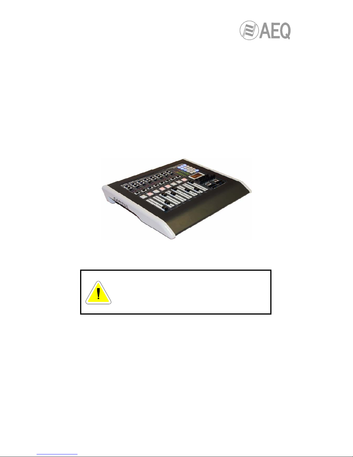
AEQ Ultra-compact digital audio mixer User manual

AEQ CAPITOL
ULTRA-COMPACT DIGITAL AUDIO MIXER
FOR BROADCAST APPLICATIONS
USER’S MANUAL
ED. 10/12
V. 1.7 - 15/09/2014
Software version 3.29, July 2014

AEQ CAPITOL
Ultra-compact digital audio mixer
2
CONTENTS
Pág.
1. INTRODUCTION............................................................................................................. 4
1.1. General overview…......................................................................................... 4
1.2. Specifications................................................................................................... 5
1.2.1. General morphology.………………..................................................... 5
1.2.2. Functionality...………………………..................................................... 5
1.2.3. General features…………………........................................................ 5
1.2.4. Standard Inputs and Outputs……....................................................... 5
1.2.5. Optional Inputs and Outputs...…......................................................... 6
1.2.6. System processing capacity…………................................................. 6
1.2.7. Dimensions and weight..…................................................................. 6
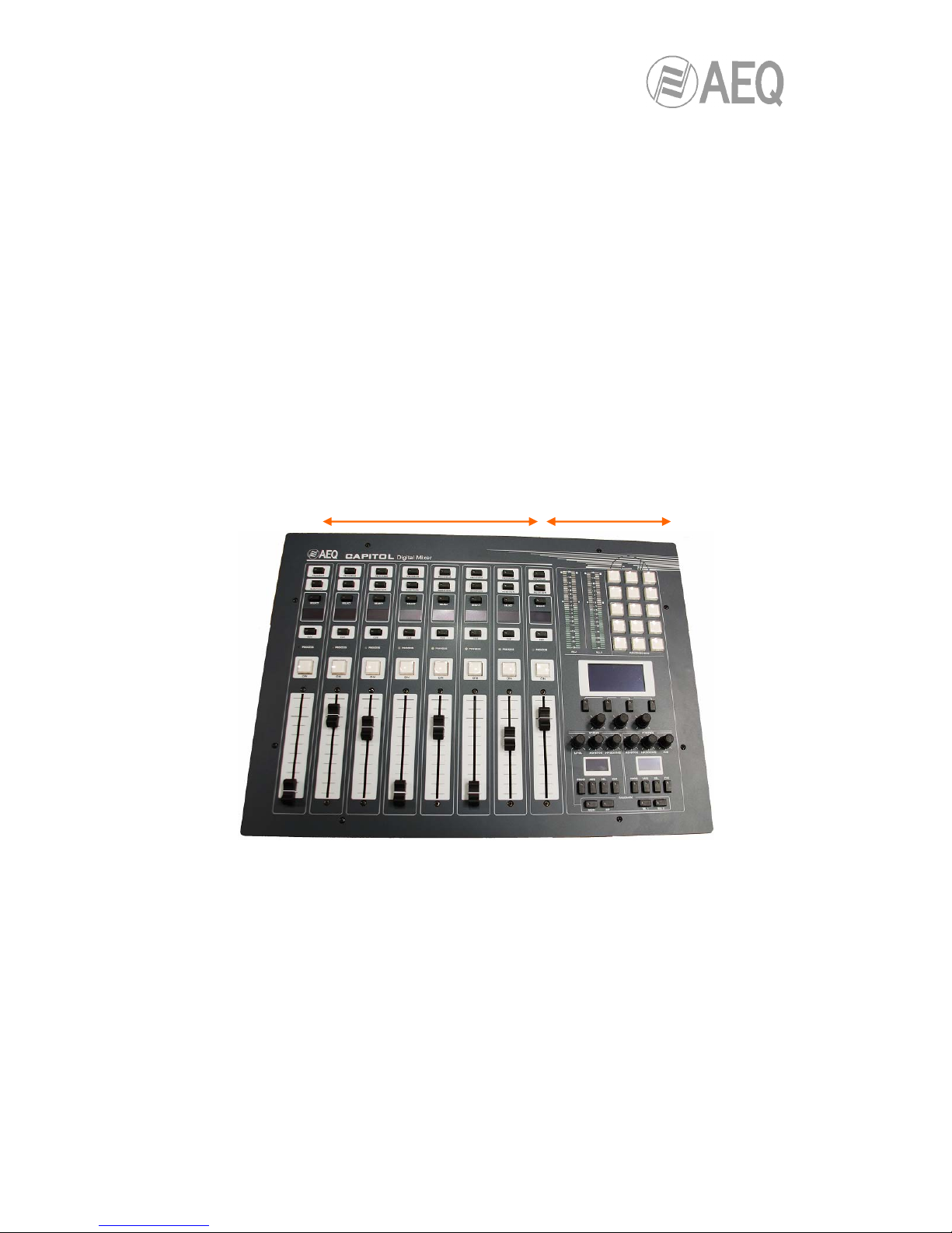
2. PHYSICAL DESCRIPTION OF THE UNIT...................................................................... 7
2.1. Description of the control surface...….............................................................. 7
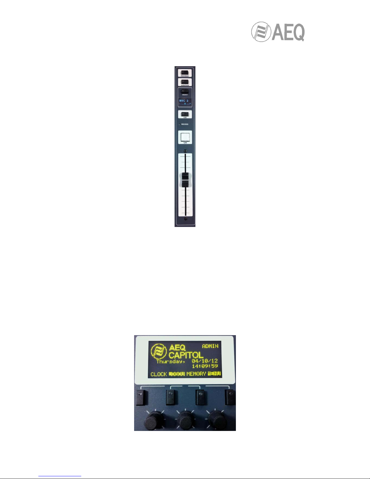
2.1.1. Chanels……………..…………………….............................................. 7
2.1.1.1. Routing keys…………………...………...................................... 9
2.1.1.2. SELECT……….………………...……….................................... 9
2.1.1.3. Channel display…..…………...………...................................... 9
2.1.1.4. CUE………………...………...................................................... 9
2.1.1.5. Active processes indicator…...…………................................... 10
2.1.1.6. Channel activation key………………........................................ 10
2.1.1.7. Fader………..…………………...……….................................... 11
2.1.2. Control and monitoring section..………………………..………………. 11
2.1.2.1. Control VU meters……………...……….................................... 12
2.1.2.2. Programmable keys.…………...……….................................... 13
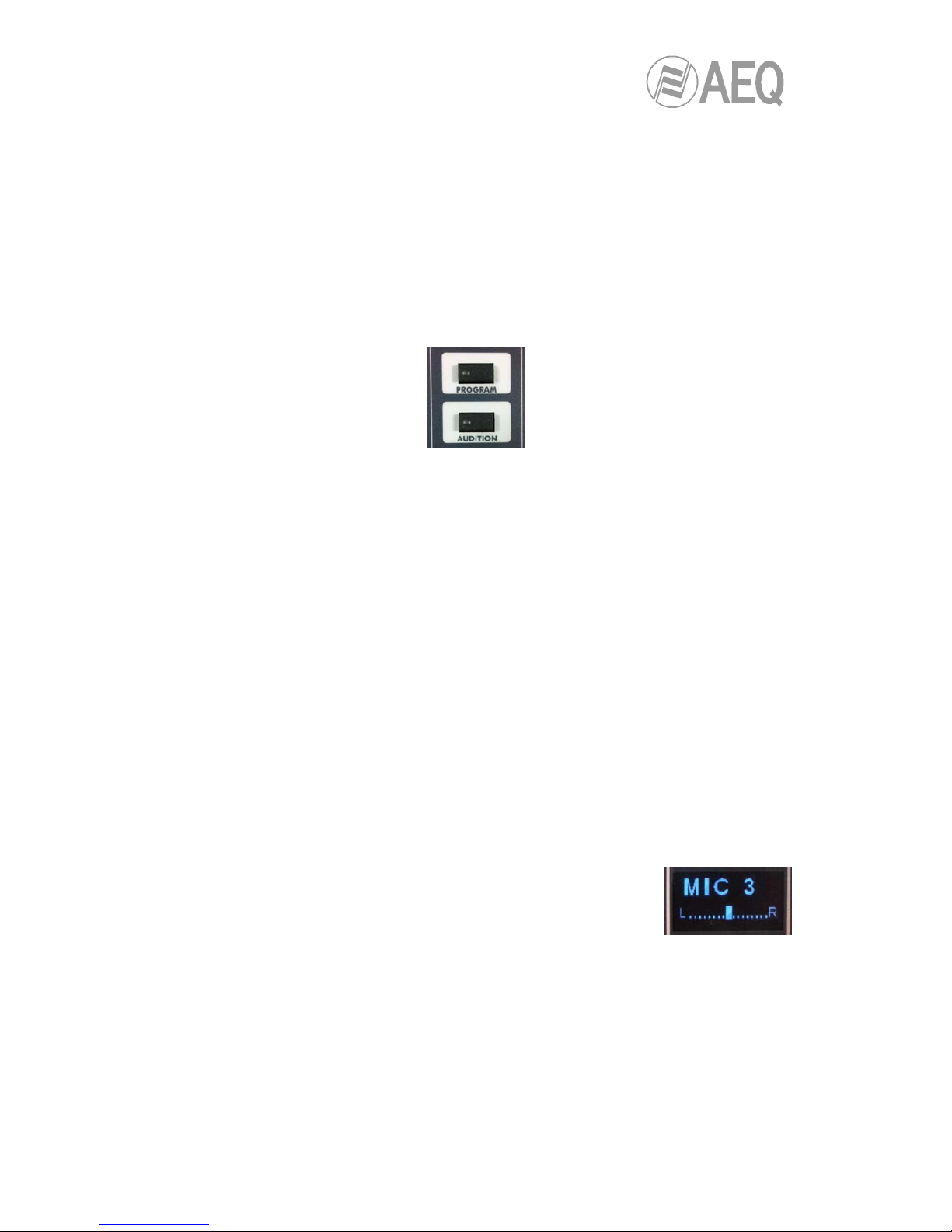
2.1.2.3. Main display……………………..……….................................... 13
2.1.2.4. Control room monitoring section.............................................. 14
2.1.2.5. Studio room monitoring section…………................................. 15
2.1.2.6. Talkback...………..................................................................... 17
2.1.3. Wrist-rest and side trims…………………………….............................. 18
2.2. Audio engine description………....................................................................... 19
2.2.1. Power supply...………......................................................................... 20
2.2.2. Auxiliary connections.…………........................................................... 20
2.2.2.1. GPIO……………………...……...……….................................... 20
2.2.2.1.1. Opto-coupled GPI...…...................................................... 21
2.2.2.1.2. Opto-coupled GPO........................................................... 21
2.2.2.1.3. Physical contact GPO...................................................... 22
2.2.2.2. Ethernet Port….………...……...………..................................... 23
2.2.2.3. Control and studio monitors…….............................................. 24
2.2.2.4. CUE……................................................................................... 24
2.2.2.5. Studio headphones……………….……..................................... 24
2.2.3. Generic audio inputs and outputs……….…….…………..................... 25
2.2.3.1. Accessing the programming jumpers…………………………... 25
2.2.3.2. Digital inputs……...................................................................... 27
2.2.3.3. Digital outputs…....................................................................... 28
2.2.3.4. Analog inputs………................................................................. 29
2.2.3.5. Analog outputs…….................................................................. 30
2.2.3.6. MIC/LINE inputs……................................................................ 31
2.2.3.7. USB inputs and outputs............................................................ 33
2.2.4. Optional inputs/outputs modules......................................................... 33
2.2.4.1. MADI communications optional module.……………………..... 33
2.2.4.2. CA33 telephone hybrid optional module…………………......... 34
2.2.5. Control headphones…........................................................................ 34
2.2.6. Wiring….……………........................................................................... 35
3. DESCRIPTION OF THE INTERNAL MENU.................................................................... 36
3.1. “CLOCK” menu…………………………..…...................................................... 36
3.2. “LOGIN/LOGOUT” menu………………..…...................................................... 38
3.3. “MEMORY” menu ...……………………..…...................................................... 40

AEQ CAPITOL
Ultra-compact digital audio mixer
3
3.4. “MAIN MENU” menu …………….……..…....................................................... 40
3.4.1. “INFO” menu..……..……………………............................................... 41
3.4.2. “SETUP” menu...……..……………………........................................... 42
3.4.3. “SELECT” menu…..……………………............................................... 43
3.4.3.1. “INPUT” menu…………………………………........................... 43
3.4.3.1.1. Dynamic menu: Compressor/Limiter and Noise Gate….. 44
3.4.3.1.2. Equalizer and filter menu...………………………………… 47
3.4.3.1.3. Expanded information menu….…………………………… 48
3.4.3.1.3.1. “FADER” menu………………………………………. 49
3.4.3.1.3.2. “ROUTE” menu…………………………………….... 49
3.4.3.2. “OUTPUT” menu………………………………........................... 50
4. CONFIGURATION SOFTWARE…..……........................................................................ 52
4.1. “Administration” menu………………..….......................................................... 54
4.1.1. “Configurations” submenu................................................................... 54
4.1.2. “User Configuration” submenu............................................................ 57
4.1.3. “About Capitol Setup” submenu…..…………………........................... 59
4.2. “Hardware Configuration” menu………………................................................. 60
4.2.1. “Board Configuration” submenu....……............................................... 61
4.2.1.1. “Internal Module Configuration” section.……………..……....... 62
4.2.2. “Mixer Bus Configuration” submenu…………..................................... 65
4.2.3. “I/O Configuration” submenu…...……………...................................... 67
4.2.3.1. Advanced configuration of input channels menu………........... 68
4.2.3.2. Advanced configuration of output channels menu................... 70
4.2.4. “Monitoring Configuration” submenu................................................... 71
4.2.4.1. “Studio Room Section”...............…........................................... 72
4.2.4.2. “Control Room Section”………….…......................................... 72
4.2.5. “NTP Client Configuration” submenu.………..………...…................... 73
4.3. “Programmable Configuration” menu………………......................................... 74
4.3.1. “Routing Configuration” submenu.…………........................................ 74
4.3.2. “Programmable Keys” submenu.……..……........................................ 76
4.3.2.1. Basic configuration of programmable keys………………......... 76
4.3.2.2. Configuration of “General” programmable keys……................ 77
4.3.2.3. Configuration of “Salvo” programmable keys.…...................... 78
4.3.2.4. Configuration of “Codec” programmable keys.......................... 80
4.3.2.5. Configuration of “Multiplex” programmable keys...................... 83
4.3.2.6. Configuration of “Cue Reset” programmable key..................... 84
4.3.2.7. Configuration of “Orders” programmable keys......................... 84
4.3.2.8. Configuration of “Memory” programmable keys....................... 85
4.3.3. “Mic Group Configuration” submenu................................................... 86
4.3.4. “Preset Configuration” submenu......................................................... 88
4.3.4.1. Advanced configuration of Compressor/Limiter…..……........... 90
4.3.4.2. Advanced configuration of Noise Gate……………………........ 91
4.3.4.3. Advanced configuration of Equalizer…...…………………........ 92
4.3.4.4. Advanced configuration of Low Pass Filter……………............ 93
4.3.4.5. Advanced configuration of High Pass Filter…………............... 93
4.3.5. “SnapShot Configuration” submenu.................................................... 94
4.3.5.1. Advanced configuration of inputs………………………............. 96
4.3.5.2. Advanced configuration of outputs….…………………............. 97
4.4. “Firmware Upgrade” menu……………………..…............................................ 99
4.4.1. “Tree View” submenu………………………......................................... 99
4.4.2. “Upgrade View” submenu.……………………...................................... 101
4.4.3. “Log View” submenu..…………………………..................................... 102
5. A.E.Q. GUARANTEE.………………………..................................................................... 103
6. ADDITIONAL INFORMATION......................................................................................... 104

AEQ CAPITOL
Ultra-compact digital audio mixer
4
1. INTRODUCTION.
1.1. General overview.
AEQ CAPITOL is an ultra-compact digital audio mixer for Radio and Television consisting in a
control surface and audio engine, specially designed for ON AIR broadcast control, and very
adaptable to different work situations. It comprises all the basic necessary functions for this kind
of environments: automatic monitor cut, cough cut, fader start, signaling control, signals for
external equipment automation, external communications management, intercom, etc.
Its reduced size makes this mixer perfectly adaptable to many different scenarios: self-control,
control-studio, audio control in television, sound production, mixed configurations, integration in
large systems, etc.
One of the main qualities of AEQ CAPITOL is the extensive internal routing capacity which
provides: 28 inputs and 30 outputs for analogue, digital or microphone audio signals, and
another 64 input/output multichannel audio over a MADI link (in order to activate this function
you must purchase a user license).
CAPITOL Standard control surface with the desktop chassis
Control power and simplicity of use has been combined into AEQ CAPITOL to meet from the
most basic to advanced operation needs, from an 8 faders control surface.
WARNING
The cable that connects control surface and audio engine
carries power supply.
In order to avoid any damage to the unit is VERY
IMPORTANT to turn off the unit before connecting or
disconnecting this cable.
All basic functions of activation, level adjustment and routing have their specific controls on
each channel of the CAPITOL surface, while less common adjustments are included in a set of
contextual controls common to all channels and accessible with just one or two keystrokes:
simplicity and clarity of use for dynamic control without handling error.
The flexibility offered through the configuration of AEQ CAPITOL enables the free assignment
of any audio input of the system to any control channel, and changing the distribution of signals
from the surface itself or the associated configuration software.
The CAPITOL digital mixer includes memory banks that store the settings for each signal:
control surface signal distribution, routing to the output buses, management of parameters and
activation of the different available audio processes. This allows the console to adapt easily to
different programs with different technical requirements.

AEQ CAPITOL
Ultra-compact digital audio mixer
5
Its Ethernet port enables the local or remote interconnectivity, facilitating set-up and
maintenance, monitoring and control.
CAPITOL has also been designed to ensure interoperability with communications equipment
and future developments by AEQ or other manufacturers.
1.2. Specifications.
1.2.1. General morphology.
•Ultra-compact design split in control surface and associated audio core.
•Control surface with 8 physical faders (100mm).
•Optional remote control software including all the functions in the control surface.
•Core: 2U 19” chassis including audio inputs and outputs, processing, power supply and
internal equipment control hardware. Optional modules for redundant power supply,
double telephone hybrid and multi-channel MADI, all of them easy to install and
maintain.
1.2.2. Functionality.
•Cough mute, studio and control room ON-AIR signalling, faderstart, remote PFL, talk-
back, automatic speaker mute.
•N-1 output configuration.
•Control of integrated external equipment (AEQ hybrids and codecs) and internal hybrids
via programmable key section.
•Optional pre-fader / post-fader routing depending on the used buses.
•Control communication via 10/100 Ethernet connection using TCP/IP protocol.
•Boot-up using last used settings.
•System signals can be assigned to any control channel.
•System settings are stored in the on-board memory: up to 7 available memory
positions.
1.2.3. General features.
•All system signals configurable for monitoring in Control, Studio, CUE Headphones and
VU-meters.
•2 direct routing buttons on each channel.
•Silent operation by convection cooling. AEQ CAPITOL is ideally suited for self-operated
applications.
•Talk-back function assigned to microphone 4, with 4 PTT buttons for direct intercom.
•2 built-in headphone outputs. In addition, a stereo line output can be assigned for
secondary headphones.
•2 precision stereo VU meters.
•Test tone (1KHz) generator.
•Externally synchronized clock, timer and stopwatch.
•Electronically balanced microphone inputs with selectable micro or line level and
Phantom power.
•Electronically balanced analog line inputs and outputs.
•Transformer balanced digital inputs and outputs.
•Sampling rate converters for the digital inputs.
•Redundant power supply (optional).
1.2.4. Standard Inputs and Outputs.
•4 mic/line mono inputs.
•2 USB digital stereo inputs/outputs.
•4 AES/EBU digital stereo inputs/outputs that can be configured as SPDIF.
•12 analog mono inputs / 8 analog mono outputs (that can be configured as individual
stereo pairs).

AEQ CAPITOL
Ultra-compact digital audio mixer
6
•Analog stereo outputs for Control, Studio, CUE and Studio primary Headphone
monitoring.
•Analog stereo amplified output for Control Headphones, jack ¼”.
•8 opto-coupled GPI’s, 8 opto-coupled GPO’s and 4 GPO’s with relays.
1.2.5. Optional Inputs and Outputs.
•Dual line Digital Telephone Hybrid with two RJ-11 Line connectors and two RJ-11
connectors for Telephone SET.
•Bi-directional MADI fiber-optic interface handling up to 64 digital inputs and outputs.
1.2.6. System processing capacity.
•48 kHz, 24 bit internal sampling frequency.
•± 12 dB gain control (analog and digital line inputs and outputs signals - including
signals not visible on control surface).
•Gain control for microphone inputs: from -36 to +19dB.
•Selectable balance/panoramic control on all channels.
•Selective phase reverse.
•Audio processing for 16 stereo signals (up to 8 on fader plus 8 signals not visible on
control surface).
•Pre-defined audio processing that allows manual adjustment.
•Available audio effects: 3 bands equalizer with adjustable Q value, high pass and low
pass filters, compressor/limiter and noise gate.
1.2.7. Dimensions and weight.
•AUDIO ENGINE or CORE UNIT: CA 01.
-Weight: 5,2 - 6 Kg (11.5 - 13.2 lbs) depending on options.
-Width: 482 mm (19“) Height: 2 RU. 89 mm. (3 1/2”). Depth: 330 mm (13”).
•CONTROL SURFACE: CA RK.
-Weight: 4 Kg (9 lbs).
-Front: Width 482 mm (19“) “) Height 8RU. 355 mm. (14”). Depth: 40 mm (1.58“).
-Cut-out for counter sinking. Width: 445 mm (17,52“) Height: 335 mm. (13,20”).
•CONTROL SURFACE : CA DT.
-Weight: 6,3 Kg (14 lbs).
-Width: 560 mm (22.04“). Height 455 mm. (17,92”). Depth: 75 mm (2.95“).

AEQ CAPITOL
Ultra-compact digital audio mixer
7
2. PHYSICAL DESCRIPTION OF THE UNIT.
AEQ CAPITOL is an ultra-compact digital mixing console consisting in a control surface and
associated audio engine. These two functional blocks, the control surface (where all the controls
and status indicators are located) and the audio engine or core unit (where all the audio
inputs/outputs, routing, sum and processing electronics is included), are connected together
with a data and power supply proprietary link with RJ45 connectors.
These functional blocks will be separately described hereunder.
2.1. Description of the control surface.
The control surface is the operators “work” area of the AEQ CAPITOL. All operational
organization, management and implementation of the audio program are accomplished from
this area. The control surface incorporates all the keys, displays, faders, encoders and VU
meters required to operate the equipment
There are two different areas on the AEQ CAPITOL control surface: the area on the left that
corresponds to the AUDIO CHANNELS controlled through faders (8 x 100mm faders) and the
CONTROL AND MONITORING AREA which is located to the right.
AEQ CAPITOL control surface
2.1.1. Channels.
AEQ CAPITOL control surface consists of 8 independent channels, each one featuring its own
dedicated 100mm fader.
The assignment of signals to channel faders on the AEQ CAPITOL is user definable. It is
possible to assign any signal to any channel fader at any time. This allows for the re-distribution
of channels in order to adapt to different programs or operators.
In addition, different channel assignment of signals can be stored in memories to be used by
different users or applications.
AUDIO CHANNELS CONTROL & MONITORING
AREA

AEQ CAPITOL
Ultra-compact digital audio mixer
8
In addition to the signals on channel faders present on the control surface that can be mixed,
processed and sent to any output channel, AEQ CAPITOL is capable of routing and adjusting
the levels for other hidden signals. Up to a total of 94x96 audio signals can be routed.
Detail of a channel module on the AEQ CAPITOL control surface
Located in the upper part of each channel are 2 routing keys (“PROGRAM“ and “AUDITION“)
and a “SELECT” button to assign the channel to advanced settings common control (gain,
dynamics, EQ and balance).
Beneath this section, an OLED display shows channel name and status for balance or pan.
Immediately under the display is located the Pre-listen button “CUE”, as well as the “PROCESS”
LED that alerts with regards to the activation or changes of equalization, dynamics
(compressors and limiters), balance or gain.
By pressing the “SELECT” button the advanced configuration functions are enabled. These
configurations are accomplished within the integrated multifunction display in the control and
monitoring section at the far right of the control surface. The operation is accomplished with the
rotary encoder and graphical menus and short-cut function keys, depending on the information
shown on the display.

AEQ CAPITOL
Ultra-compact digital audio mixer
9
Among the general functions are the instant activation and adjustment of audio effects (EQ,
filters, limiters, etc.), configurations and memories management, disconnection of the effects
applied, phase change, inserting of a test signal, as well as clock, timer and stopwatch for
timing control, etc. For more information see chapter “3. DESCRIPTION OF THE INTERNAL
MENU” of this manual.
The channel module is completed with the Channel ON button and the sliding fader.
2.1.1.1. Routing keys.
There are two keys on the top of the channel that routes the channel signal to the
corresponding output bus. Activation is indicated through the integrated LED in each of these
keys, and indicates the creation of a cross point between the input signal on the channel and
the output channel corresponding to the key.
Detail of routing keys
The two keys for direct routing are “PROGRAM“ (sending to master 1) and “AUDITION“
(sending to master 2). The allocation of physical outputs associated with these signals and the
physical circuits of the inputs/outputs modules on the back of AEQ CAPITOL is accomplished
from the configuration software. For more information, please refer to chapter “4.
CONFIGURATION SOFTWARE” of this manual.
2.1.1.2. SELECT.
The control surface of AEQ CAPITOL offers the usual controls and indicators for a mixing
console on each channel, but AEQ CAPITOL also offers a wide range of possibilities for routing
and processing, beyond the physical options included in each channel. These possibilities have
been distributed in a logical manner within internal menus accessible from the main screen of
the Control and Monitoring section.
The operation is intuitive, always beginning with pressing the “SELECT” button on the channel
that you want to process and moving to the main screen of the Control and Monitoring section
of the console to accomplish the activations or adjustments. For further details please refer to
chapter 3.4.3.1 of this manual.
2.1.1.3. Channel display.
Each one of the 8 channels on the AEQ CAPITOL integrates a two-colour OLED display
showing:
•Name of the associated audio signal (maximum 6 characters,
editable via the configuration software). For more information see
chapter “4. CONFIGURATION SOFTWARE” of this manual.
•Status of balance between left (L) and right signal (R) in stereo
signals (or panoramic for monophonic signals).
2.1.1.4. CUE.
This button allows you to activate a pre-fader listening to the audio channel for monitoring and
control. When activated the integrated LED is lit. It is possible to send the audio signals of
several channels to the CUE bus, acting as a summing bus.

AEQ CAPITOL
Ultra-compact digital audio mixer
10
There is the option of setting one of the programmable keys on the Control and Monitoring
section (C&M) as a general “CUE RESET” that disconnects all active signals from the CUE bus.
CUE signal associated controls
CUE volume is controlled by means of an encoder in the Control and Monitoring zone. A
dedicated stereo output for a set of external active speakers is provided in the “CUE” connector
(a 1/8” or 3,5mm stereo minijack), at the back of the AEQ CAPITOL audio core. It is compatible
with most PC speakers.
2.1.1.5. Active processes indicator.
Under the “CUE” button there is a blue LED with a “PROCESS” label. When lit, this indicates
the activation or change of any of the following fields: EQ, filters, dynamics (compressors and
limiters), balance or gain.
These four processes (EQ, dynamics, balance and gain) are controlled from the internal menu
associated with the “SELECT” button on the main screen of the Control and Monitoring section.
2.1.1.6. Channel activation key.
The channel activation key, also known as “CHANNEL ON/OFF” key is placed under the active
processes indicator. This key enables or disables audio to pass from the channel input to the
previously defined outputs.
This key can also be remotely activated by means of GPI. In order to configure remote
activation, please refere to chapter 4.2.3.1 of this manual.
CUE SELECTION CUE RESET CUE VOLUME
CUE SENDING TO
CRM AND CRHP (control
monitors and headphones)
CUE SENDING TO
SRM AND SRHP (studio
monitors and headphones)

AEQ CAPITOL
Ultra-compact digital audio mixer
11
2.1.1.7. Fader.
100mm. fader. The fader travel is printed with 11 bands, the maximum output level +22dB
corresponding to the last, and the third band from above to +0dB or nominal operating level.
Both of these marks are differentiated in size from the rest.
Detail of 100mm fader calibration
The response mode of the fader is logarithmic, producing great attenuation of the level at the
bottom of the fader travel and less adjustment at the top.
The bottom position of the fader travel triggers gain -∞dB or absence of signal.
2.1.2. Control and monitoring section.
The control and monitoring section (C&M) of the control surface is located to the right. This
section enables the overall management of the signals on the system, including routing and
control processes, as well as monitoring of the signals used in developing the final program, by
means of the VU-Meters, and CUE control.
This control and monitoring section is divided into four main areas:
•Control VU meters: allows you to monitor visually the level of the audio signals from
the master output and the CUE bus (or the control monitoring bus, when there are no
channels sent to CUE).
•Programmable keys: dedicated buttons with special functions defined through the
configuration software.
•Main screen: it displays the internal menus. This section also incorporates contextual
keys and encoders.
•Studio, Control and Talk-back monitoring: where you can manage the audio signals
sent to the headphones and speakers, for the control room and the studio room, as well
as the talk-back functions for the intercom for both areas.
+22dB
+0dB

AEQ CAPITOL
Ultra-compact digital audio mixer
12
2.1.2.1. Control VU meters.
There are two 40 segment LED stereo VU meters. The left one shows the Program output and
the right one the CUE bus (or the control monitoring bus, when there are no channels sent to
CUE).
From bottom to top, the first 25 LEDs are green, followed by an area of 5 yellow LEDs to finish
with an area of 10 red LEDs. 0dB point or nominal value corresponds to the the first yellow LED
adjacent to the last green LED.
Detail of control vumeters
Both VU meters are set to function as IEC268-10: 5ms/-2dB (vu-meter only) and the peak-meter
IEC268-17: 300 ms (vu-meter & Flying PPM) superimposed.
VU meters
CONTROL AND
STUDIO
MONITORING
AND TALKBACK
PROGRAMMABLE
KEYS
MAIN
SCREEN

AEQ CAPITOL
Ultra-compact digital audio mixer
13
2.1.2.2. Programmable keys.
The Control and Monitoring area of the AEQ CAPITOL includes 15 programmable keys in five
rows of 3 columns.
These programmable keys can be configured through software to perform specific functions
such as salvos, GPI, GPO, external codecs control. For more information see section 4.3.2 of
this manual.
The operation of the programmable keys contemplates two modes:
•NORMAL: the pressing of the key triggers the the execution of the programmed action.
Pressing it again will produce the end of the previously launched action, or in the case
of SALVOS, even the opposite action or disconnection of the SALVO.
•PTT (PUSH-TO-TALK): the pressing of the key will trigger the execution of the
programmed action but only remains active as long as you keep the button pressed.
All keys can be easily labelled, removing the transparent plastic cover and inserting a text label.
AEQ supplies with the equipment a template that allows you to create these labels on clear
acetate or plain paper.
2.1.2.3. Main display.
The main screen is a two coloured OLED (yellow/black) 128x64 pixel resolution display that
shows the entire internal advanced menu of the AEQ CAPITOL. For more information see
section “3. DESCRIPTION OF THE INTERNAL MENU” of this manual.
To simplify operations on the internal menu shown on this display there are four short-cut keys
and three associated rotary encoders. Depending on the information shown on the last line of
the menu display visible on the main display, these short-cut keys will have a function or
another.

AEQ CAPITOL
Ultra-compact digital audio mixer
14
At most, the last line will have four menu options visible from left to right, and they are directly
associated with short-cut keys from left to right.
The three rotary encoders are related to the remaining lines of the menu. Each display is
described in chapter 3 of this manual but the thumb-rule for the association of the rotary
encoder to the visible functions is: option visible to the left or in the upper part of the menu is
controlled from the encoder located to the left. In many cases the encoders are represented and
labelled on the display for easy operation.
2.1.2.4. Control room monitoring section.
Located in the lower right corner of the AEQ CAPITOL control surface are a two-coloured
display, three rotary encoders and four keys (one of them, “SEL”, a short-cut key).
•In the two-coloured OLED display are shown the output levels for the control monitoring
signals and the selected sources in each case, for control headset, control speakers
and CUE.
•The three rotary encoders, from left to right, are:
o“MONITOR“: it controls the audio level for the physical output for the control
room monitors. To decrease the level turn the encoder to the left. To increase
the level turn the encoder to the right.
MAIN
DISPLAY
SHORT-CUT
KEYS
ROTARY
ENCODERS

AEQ CAPITOL
Ultra-compact digital audio mixer
15
o“HP/SOURCE“:it controls the audio level for the physical output for the control
headphones. To decrease the level turn the encoder to the left. To increase the
level turn the encoder to the right. This encoder can also be used to select the
signal to monitor associated with the key “SEL”: press to access a list of
signals, and turn the encoder to move up or down in the list of signals; pushing
the encoder a second time confirms the selection of the highlighted signal.
o“CUE“:it controls the audio level of the CUE speakers .To decrease the level
turn the encoder to the left. To increase the level, turn the encoder to the right.
•The four keys under the display allows to select the signal to monitor on control
speakers and headset, from left to right:
o“PROG“: allows you to monitor the audio signal Program.
o“AUD“: allows you to monitor the audio signal Audition.
o“SEL“: allows you to monitor any signal of the console previously selected by
means of “HP/SOURCE“ encoder.
o“CUE“: allows you to monitor the audio signal present on the CUE bus.
These four keys can have two working modes that are selected from the Configuration
Software (see section 4.2.4 of this manual):
o“Mixer”:each key pressed adds the signal to be monitored to the summing bus.
o“Exclusive”:each key pressed connects the signal to the summing bus and
disconnects any signal previously selected.
In case there are no channels sent to CUE, the signal or signals selected in this section
will be shown in the rigth control VU meter (see section 2.1.2.1 of this manual).
2.1.2.5. Studio room monitoring section.
Located in the lower left corner of the AEQ CAPITOL control surface are a two-coloured display,
three rotary encoders and four keys (one of them, “SEL”, a short-cut key).
•In the two-coloured OLED display are shown the output levels for the studio monitoring
signals and the selected sources in each case, for studio headset, studio speakers and
talkback.

AEQ CAPITOL
Ultra-compact digital audio mixer
16
•The three rotary encoders, from left to right, are:
o“LEVEL” (Talkback Level): it controls the gain of the TALKBACK microphone.
To decrease the level, turn the encoder to the left. To increase the level, turn
the encoder to the right.
o“MONITOR“: it controls the audio level for the physical output for the studio
room monitors. To decrease the level, turn the encoder to the left. To increase
the level, turn the encoder to the right.
o“HP/SOURCE“:it controls the audio level for the physical output for the studio
headphones. To decrease the level, turn the encoder to the left. To increase the
level, turn the encoder to the right. This encoder can also be used to select the
signal to monitor associated with the key “SEL”: press to access a list of
signals, and turn the encoder to move up or down in the list of signals; pushing
the encoder a second time confirms the selection of the highlighted signal.
•The four keys under the display allows to select the signal to monitor on studio
speakers and headset, from left to right:
o“PROG“: allows you to monitor the audio signal Program.
o“AUD“: allows you to monitor the audio signal Audition.
o“SEL“:allows you to monitor any signal of the console previously selected by
means of the “HP/SOURCE“ encoder.
o“CUE“:allows you to monitor the audio signal present on the CUE bus.
These four keys can have two working modes that are selected from the Configuration
Software (see section 4.2.4 of this manual):
o“Mixer”:each key pressed adds the signal to be monitored to the summing bus.
o“Exclusive”:each key pressed connects the signal to the summing bus and
disconnects any signal previously selected.

AEQ CAPITOL
Ultra-compact digital audio mixer
17
2.1.2.6. Talkback.
Talk-back section allows the console operator to communicate directly with the studio and
remote guests (lines).
The default intercom channels for the AEQ CAPITOL are established between the control room
and the studio with separate channels for monitors and headphones. You can set additional
channels of intercom to facilitate communications. For example, talk-back can be established
between studio or control to the different audio returns to hybrids or audio-codecs. The talk-
back microphone can also be used as an auto-control microphone if so defined.
The talk-back section of the control surface consists of 4 key buttons immediately beneath the
Studio and Control sections and the encoder “LEVEL” (Talkback Level) of the Studio monitoring
section.
From left to right are:
•“MON“: talk-back to studio monitors.
•“HP“: talk-back to studio headphones. The default configuration of the AEQ CAPITOL
does not differentiate between primary and secondary headphones. It is possible to
establish a secondary group of headphone creating a salvo to be triggered from the
programmable keys.
•“TEL 1“: talk-back to the telephone hybrid line 1 (AEQ CAPITOL can work with an
optional 2 lines digital hybrid module, but has 8 MPX internal buses hidden that can be
used with dedicated lines, external audio codecs or telephone hybrids. The talk-back to
dedicated lines, external audio-codecs or telephone hybrids can be established through
the use of the programmable keys).
•“TEL 2“: talk-back to the telephone hybrid line 2.
TALKBACK
MIC GAIN
TALKBACK
SEND

AEQ CAPITOL
Ultra-compact digital audio mixer
18
2.1.3. Wrist- rest and side trims.
AEQ CAPITOL control surface is provided in two different configurations:
•Desktop or Table top (TT):
AEQ code 732.000.700 – AEQ CAPITOL digital compact table-top mixing console.
•Counter-sunk (CS), to be built into technical furniture:
AEQ code 732.000.701 – AEQ CAPITOL digital compact counter-sunk mixing console.
Table-top AEQ CAPITOL features a frame around the sides, upper and lower part of the control
surface. This frame adopts the shape of a wrist-rest at the lower side, in oven dried lacquereed
steel that suffers minimal wear of use.
AEQ CAPITOL TT
The wooden side trims allow for an easy recognition of the equipment and are integer part of
the chassis. They also have the function as a finishing element for table-top installations of the
mixing console.
AEQ CAPITOL CS option, on the other hand, is provided without these trims and the metal
frame that supports them, ready for the integration into a supporting tabletop. This way the
controls surface will form a homogeneous part of the technical furniture, leveled with the surface
of the table or desktop.
AEQ CAPITOL CS

AEQ CAPITOL
Ultra-compact digital audio mixer
19
2.2. Audio engine description.
AEQ CAPITOL is an ultra-compact digital audio mixer for Radio and Television consisting in a
control surface and an associated audio engine, specially designed for ON AIR broadcast
control, highly adaptable to different operational situations. The following chapters will describe
AEQ CAPITOL audio engine.
The AEQ CAPITOL audio engine or core unit consists in a 2RU chassis (89mm or 3 1/2”
height), designed to be installed in standardizedd 19” (482mm) racks. As with the rest of AEQ
CAPITOL, the audio engine size has been minimized without leaving any feature out, its depth
being only 330mm.
AEQ CAPITOL audio engine does not have any fans or moving mechanical parts for cooling.
Therefore its operation is totally silent and can thus be installed inside radio studios. The unit
cooling relies on convection air flow. For this reason it is strongly recommended to leave some
space above and below the equipment. It also takes advantage of the good thermal conductivity
properties of the metal elements of the chassis to channel the residual heat to the front panel,
where it is dissipated.
Ease of installation and set up been a priority during the design of CAPITOL, so audio input and
output, control monitoring and auxiliary signals configurations of the mixing console are fixed
and defined from Factory:
•4 balanced microphone / line level inputs.
•12 line level balanced mono analog inputs.
•4 AES/S/PDIF digital stereo inputs.
•8 line level balanced mono analog outputs.
•4 AES/S/PDIF digital stereo outputs.
•2 stereo input/output USB computer connections.
•Control and Studio headphone outputs.
•Stereo unbalanced CUE output with line level.
•Stereo balanced analog outputs with line level for control and Studio monitors.
In order to connect external cough-cuts, remote control external devices, ON AIR lights, etc,
AEQ CAPITOL features 8 general purpose digital inputs (GPI), 8 outputs (GPO) and another 4
relay-switched outputs. The system configuration and remote control is carried out through an
IP based Ethernet connection.
AEQ CAPITOL has an optional bi-directional MADI interface (optional and subject to a specific
user license) that can carry up to 64 digital inputs and outputs as well as two optional digital
telephone hybrids.
For ease of wiring and avoid errors in the installation process, audio and data cables with DB15
male connectors required to connect the console can be optionally supplied. In any event, it is
necessary to use shielded and balanced audio cables and that the connection to the DB
connectors are made by technically qualified personnel and properly verified before connecting
the equipment. Further, optional power supply and wiring for control and studio signalling and
GPIO can be supplied.

AEQ CAPITOL
Ultra-compact digital audio mixer
20
2.2.1. Power supply.
The power supply module is located at the left of the audio engine back panel (as seen from the
rear). It supplies the internal voltages to the console and to the control surface. It consists on a
universal auto-range switching power supply that can operate with worldwide mains: 90 - 132 V
AC & 187 – 264 V AC, 47/63Hz. The max power consumption is 65VA.
Optionally, a second (backup) power supply can be installed in order to have redundancy. This
second power supply includes installation instructions. If two power supplies are used, it is
recommended that one of them is connected to a UPS while the other can be connected to
regular mains or domestic power.
The console/engine data and power supply interconnection is located at the right of the power
supply inputs. It is designed for use with straight Ethernet cabling, but also carries proprietary
power supply lines. Please use the cable provided with the unit only.
IMPORTANT NOTE: Do not connect this output to any device but the cotrol surface (there
is a severe risk of damage to other equipment or even the audio engine itself). In order to avoid
any damage to the unit is VERY IMPORTANT to turn off the unit before connecting or
disconnecting this cable.
2.2.2. Auxiliary connections.
This area of the AEQ CAPITOL back panel includes a wide variety of inputs and outputs,
required to integrate the unit with any professional audio installation, including several
headphone and external speaker outputs, general purpose inputs and outputs, control and
studio speakers.
Among these auxiliary console inputs and outputs, you can find not only analog signals such as
headphones, speakers or CUE, but also general purpose inputs and outputs GPIOs (both open-
collector and relay switched), and finally the control and configuration interfaces with an external
computer running the associated setup and remote control software.
2.2.2.1. GPIO.
AEQ CAPITOL includes many general purpose inputs and outputs using optocouplers and relay
contacts, all of them made available at the back panel of the audio engine.
This manual suits for next models
1
Table of contents
Other AEQ Music Mixer manuals