aerauliqa AIRQURE P1 User manual

AIRQURE - P1
MANUALE DI INSTALLAZIONE, USO E MANUTENZIONE 2
INSTALLATION, USE AND MAINTENANCE MANUAL 12
MANUEL D’INSTALLATION, D’UTILISATION ET D’ENTRETIEN 22
I
GB
FR

2
Leggere questo manuale attentamente prima di utilizzare il prodotto e conservarlo in un posto sicuro così da poterlo consultare
all’occorrenza.
Il prodotto è costruito a regola d’arte e nel rispetto delle normative vigenti in materia di apparecchiature elettriche e deve essere
installato da personale tecnicamente qualificato.
La ditta costruttrice non si assume responsabilità per danni a persone o cose derivanti dalla mancata osservanza delle norme
contenute nel presente libretto.
1 Indice 2
2 Avvertenze e Precauzioni 3
3 Informazioni di prodotto 3
3.1 Generale 3
3.2 Dimensioni e Peso 4
3.3 Spazio richiesto 4
3.4 Etichette dati 4
4 Trasporto e Stoccaggio 4
5 Installazione 4
5.1 Rimozione dell’imballo 4
5.2 Dove/come installarlo 4
5.3 Cosa contiene l’imballo 5
5.4 Installazione diffusore 5
5.5 Installazione a soffitto 5
5.6 Installazione a pavimento 6
5.7 Collegamenti elettrici precablati 6
6 Messa in servizio e funzionamento 8
6.1 AIRQURE P1-N 8
6.2 AIRQURE P1-H 8
6.2.1 Settaggio velocità minima continua 8
6.2.2 Settaggio velocità massima 8
6.2.3 Settaggio velocità intermedia (modalità Heat Recovery) 9
6.2.4 Settaggio soglia intervento temperatura (modalità Heat Recovery) 9
6.2.5 Settaggio soglia intervento temperatura (modalità Stand-by estivo) 9
6.2.6 Settaggio soglia intervento temperatura della batteria riscaldante 9
6.2.7 Velocità minima continua 9
6.2.8 Velocità massima 9
6.2.9 Modalità Heat Recovery 9
6.2.10 Modalità Stand-by estivo 9
6.2.11 Attivazione elemento riscaldante 10
6.2.12 Funzionamento a due velocità con comando CTRL-P1 (accessorio su richiesta) 10
6.2.13 Controllo tramite Modbus 10
7 Manutenzione 10
8 Smaltimento e riciclaggio 11
9 Fiche tecnica ErP 32
1 INDICE
AIRQURE P1
VMC a singolo flusso canalizzata per immissione con pressione positiva

3
2 AVVERTENZE E PRECAUZIONI
Trasporto e stoccaggio
•Nonlasciarel’apparecchioespostoadagentiatmosferici(pioggia,sole,neve,etc.).
•Iraccordiperlaconnesionealletubazionidevonoessereprotettidurantelostoccaggioel’installazione.
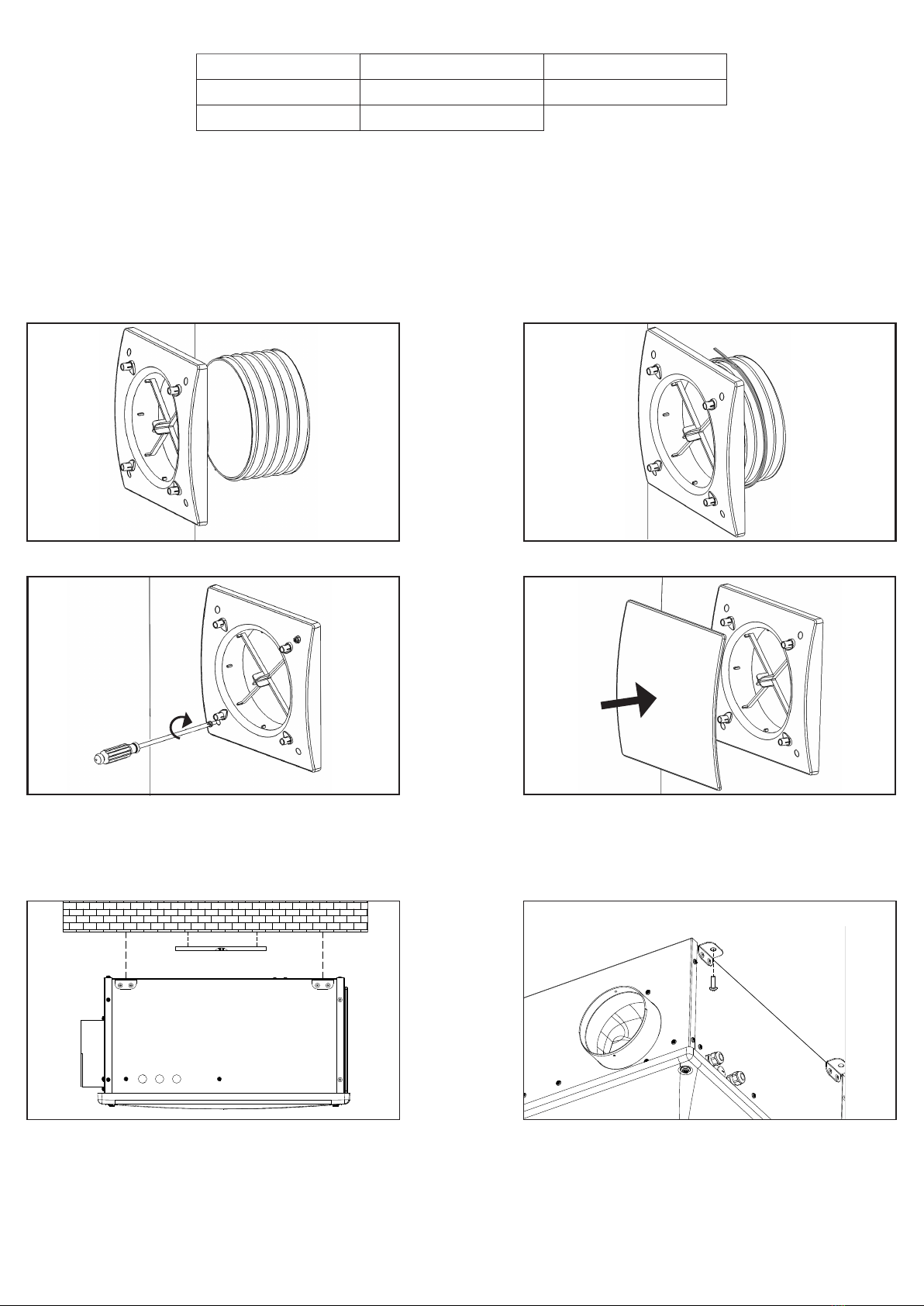
Installazione
•Dopo aver rimosso il prodottodall’imballo, vericarne l’integrità. Non lasciare parti dell’imballo alla portata di bambini o
persone diversamente abili.
•Fareattenzioneagliangolitaglienti.Utilizzareguantidiprotezione.
•L’apparecchionondeveessereimpiegatocomeattivatorediscaldabagni,stufe,ecc.,nédevescaricareincondottiadibiti
all’evacuazione di aria calda/fumi derivanti da alcun tipo di apparecchio a combustione.
•Qualoranell’ambienteincuièinstallatoilprodottosiapresenteunapparecchiofunzionanteacombustibile(scaldacqua,stufaa
metanoetc.,ditiponona“camerastagna”),èindispensabileassicurareunadeguatoingressod’aria,pergarantireunabuona
combustione e il corretto funzionamento di tali apparecchi.
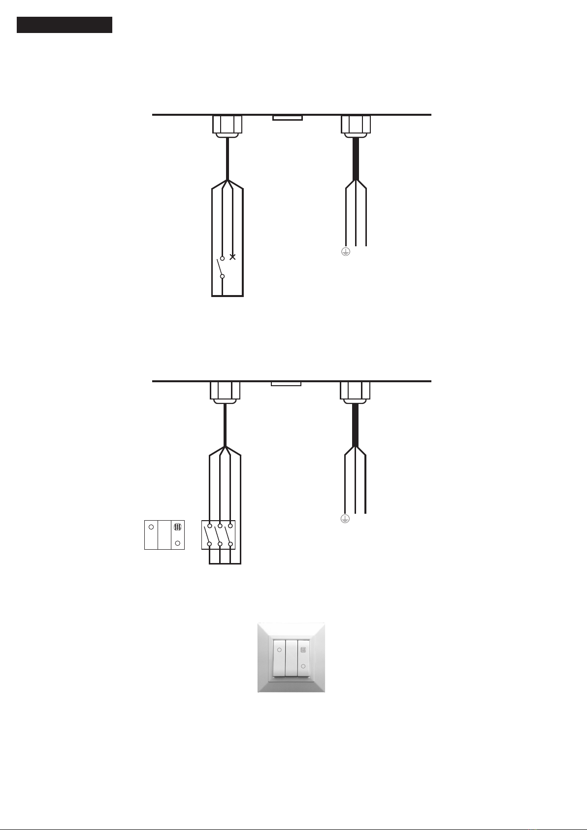
•Seilcavodialimentazioneèdanneggiato,essodeveesseresostituitodalcostruttoreodalsuoservizioassistenza
tecnicaocomunquedaunapersonaconqualicasimilare,inmododaprevenireognirischio.
•L’impiantoelettricoacuiècollegatoilprodottodeveessereconformeallenormativevigenti.
•Primadicollegareilprodottoallaretedialimentazioneoallapresaelettricaaccertarsiche:
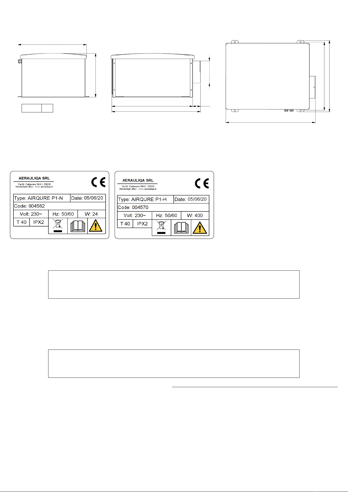
- i dati di targa (tensione e frequenza) siano rispondenti a quelli della rete di distribuzione elettrica;
- la portata dell’impianto/presa sia adeguata alla potenza massima dell’apparecchio.
•Perl’installazioneoccorreprevederenellaretedialimentazione,conformementealleregolediinstallazione,uninterruttore
onnipolare che consenta la disconnessione completa nelle condizioni della categoria di sovratensione III (distanza dei contatti
uguale o superiore a 3mm).
• Assicurare un adeguato rientro dell’aria nel locale, nel rispetto del regolamento vigente, al ne di garantire il corretto
funzionamento dell’apparecchio.
•Effettuarel’installazioneinmodochelagirantesiainaccessibileallatodellamandata,alcontattodelDitodiProva(sondedi
prova“B”dellanormaEN61032),secondolevigentinormeantinfortunistiche.
Utilizzo
•L’apparecchionondeveessereutilizzatoinapplicazionidiversedaquelleindicateinquestomanuale.
•Questoapparecchiopuòessereutilizzatodabambinidietànoninferioread8anniedapersoneconridottecapacitàsiche,
sensorialiomentalioconesperienzaeconoscenzeinsufcienti,purchéattentamentesorvegliateoistruitesucomeutilizzare
inmodosicurol’apparecchioesuipericolicheciòcomporta.Assicurarsicheibambininongiochinoconl’apparecchio.Pulizia
e manutenzione da parte dell’utente non devono essere eseguite da bambini senza supervisione.
•Nontoccarel’apparecchioconmani/piediumidiobagnati.
•L’apparecchioèdestinatoadimmetteresoloariapulita,ossiasenzaelementigrassi,fuliggine,agentichimiciecorrosivi,
miscele infiammabili o esplosive.
•Nonimpiegareilprodottoinpresenzadisostanzeovaporiinammabili,comealcool,insetticidi,benzina,etc.
•Il sistema deve rimanere in funzione continuamente e fermato solo durante le operazioni di manutenzione
ordinaria e straordinaria.
•Nonostruirelagrigliadiaspirazioneodiespulsionepergarantirel’ottimalepassaggiodell’aria.
•NonimmergereI’apparecchiooaltresuepartiinacquaoliquidi.
•Temperaturadifunzionamento:da0°Cnoa+40°C.
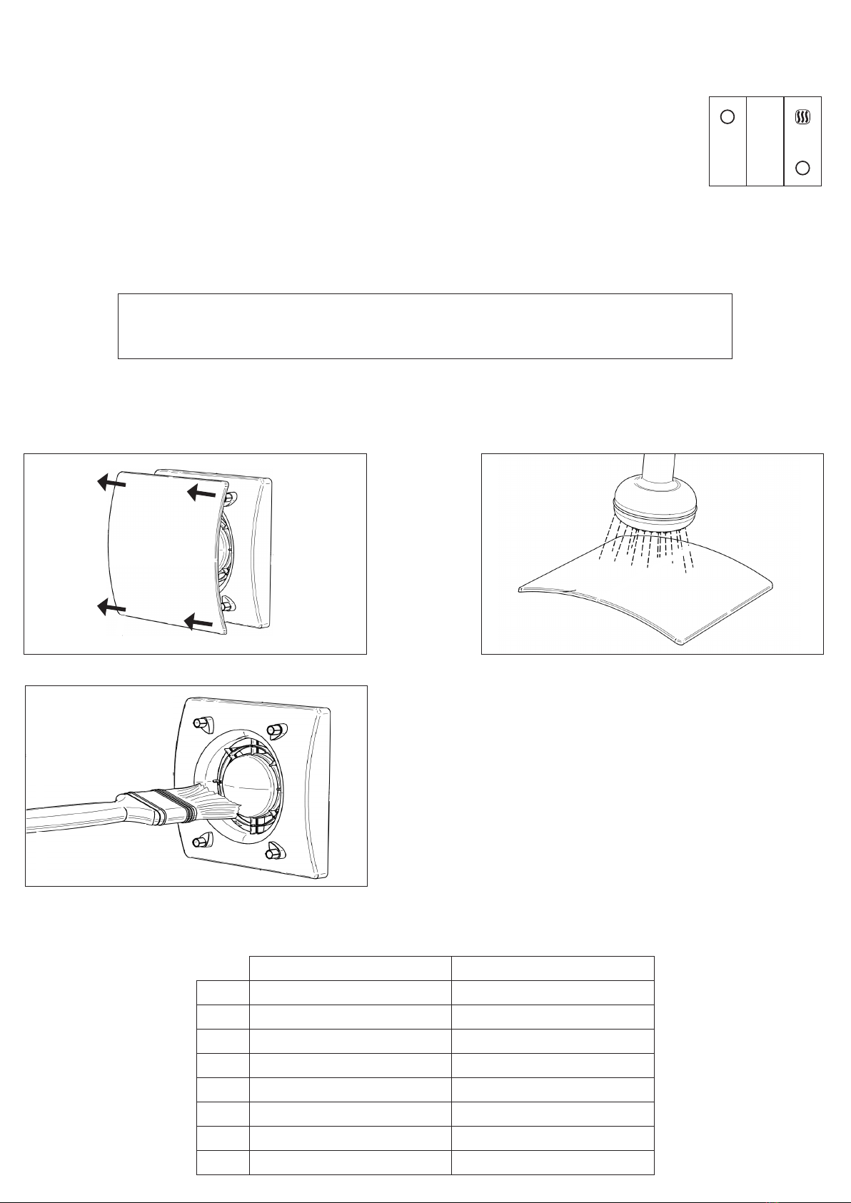
Manutenzione
•Sebbeneilprodottosiastatodisconnessodallareteelettrica,sussisteilrischiodilesioniacausadellepartiancorainmovimento.
•Fareattenzioneagliangolitaglienti.Utilizzareguantidiprotezione.
•Incasodiriparazioneutilizzaresoloricambioriginali.
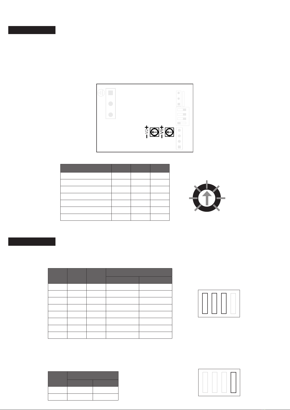
3 INFORMAZIONI DI PRODOTTO
3.1 Generale
IlmodelloAIRQUREP1èun’unitàdiVMCperimmissioneapressionepositiva,progettataperimmetterearia,eventualmente
ltrataeriscaldata,nelvanoscalaonelcorridoioprincipale,prelevandoladalsottotettodiunacasaindipendente.
Non necessita di sistema di canalizzazione.
ATTENZIONE
Assicurarsi che l’interruttore generale dell’impianto sia spento prima di qualsiasi operazione
diinstallazione,manutenzioneordinariaostraordinariaocollegamentoelettrico!
L’installazione e la manutenzione dell’unità e del sistema di ventilazione completo deve essere
eseguito da un installatore autorizzato e in conformità alle leggi e ai regolamenti vigenti.
Qualorasirileviun’anomaliadifunzionamento,scollegareilprodottodallarete
elettrica e contattare immediatamente un tecnico qualificato.

4
3.4 Etichette dati
3.3 Spazio richiesto
Assicurarsi che attorno all’unità vi sia spazio sufficiente per lo svolgimento delle attività di manutenzione (accessibilità ai filtri e
alla scatola collegamenti elettrici e rimozione dei pannelli di ispezione laterali e frontali).
3.2 Dimensioni (mm) e Peso (kg)
Fig.3.c Etichette dati.
4 TRASPORTO E STOCCAGGIO
Il prodotto è fornito in una scatola di cartone.
Ilprodottodeveesserestoccatoetrasportatoinmodochesiasempreprotettodadannisicichepossonoguastarelebocche,
lacarcassa,ildisplay,ecc...
Deveesserecopertoinmodochelapolvere,lapioggiaelanevenonpossanoentrareedanneggiarel’unitàeisuoicomponenti.
5 INSTALLAZIONE
Questa sezione descrive come installare l’unità correttamente. L’unità deve essere installata seguendo queste istruzioni.
5.1 Rimozione dell’imballo
Verificare che l’unità (e gli eventuali accessori) siano conformi a quanto ordinato prima di procedure all’installazione. Eventuali
discrepanze rispetto a quanto ordinato devono essere comunicate al fornitore.
5.2 Dove/come installarlo
•L’unitàAIRQUREP1èintesaperinstallazioneall’interno,inzoneriscaldate.
•L’unitàpuòessereinstallataorizzontalmente.
•Montarel’unitàsusupercipiane(softtoopavimento).
•E’importantechel’unitàsiacompletamentepostaalivelloprimadiessereattivata.
•Scegliendolazonaprestareattenzionechel’unitàrichiedediunamanutenzioneperiodicaecheilpannellodiispezionedeve
rimane facilmente accessibile.
•Lasciarespazioliberoperl’aperturadelpannelloeperl’estrazionedeiprincipalicomponenti.
Peso 8,3
Adattoperinstallazioneasofttoopavimento,inqualsiasiposizione.
Il modello AIRQURE P1-H è equipaggiato con batteria riscaldante.
386
247
457
500
44
Ø124,5
506
385
404
ATTENZIONE
Assicurarsi che le avvertenze e le precauzioni indicate nel Capitolo 2
sianoattentamentelette,compreseerispettate!
ATTENZIONE
Assicurarsi che le avvertenze e le precauzioni indicate nel Capitolo 2
sianoattentamentelette,compreseerispettate!

5
1. Unità di ventilazione 4. Manuale 7. 2x Fascette metalliche
2. Pre-Filtro 5. Diffusore 8. 2x Alette Mylar
3. Tubo 6.Viti+tasselli
Fig. 5.a Fig. 5.b
5.3 Cosa contiene l’imballo
5.4 Installazione diffusore
Quando si monta il diffusore vicino a un rilevatore di fumo le alette di direzione del flusso (fornite) devono essere montate in modo
da evitare che soffino aria sopra il rilevatore di fumo e che influiscano sul suo funzionamento.
Sel’unitàvieneinstallatainun’abitazionedi3opiùpiani,essadovrebbeesserecollegataadunrilevatoredifumodimodoche
l’alimentazione venga rimossa dall’unità quando l’allarme fumo è attivato.
Il nostro diffusore standard non è adatto per essere installato in abitazioni con 3 o più piani o in aree protette dal fuoco.
In caso di installazione di un’unità AIRQURE P1-H (con elemento riscaldante) il tubo flessibile deve essere il più corto possibile.
In alternativa utilizzare un tubo isolato termicamente (accessorio su richiesta).
Fig. 5.c Fig 5.d
5.5 Installazione a soffitto
L’unità deve essere installata come segue.
Fig. 5.e
Livello di bolla
Fig. 5.f
5.ePrepararelasuperciesullaqualel’unitàdeveesseremontata.Assicurarsicheessasiapiana,livellataechesiacostruita
in modo da poter sostenere il peso dell’unità. Effettuare l’installazione conformemente a quanto richiesto dalle norme e
regolamenti locali in vigore.
5.f Utilizzare la viteria appropriata (non fornita) per fissare l’unità al soffitto. Si raccomanda di montare l’unità utilizzando dei
giunti antivibranti (non forniti).

6
5.6 Installazione a pavimento
L’unità deve essere installata come segue.
Fig. 5.g
Livello di bolla
Fig. 5.h
5.gPrepararelasuperciesullaqualel’unitàdeveesseremontata.Assicurarsicheessasiapiana,livellataechesiacostruita
in modo da poter sostenere il peso dell’unità. Effettuare l’installazione conformemente a quanto richiesto dalle norme e
regolamenti locali in vigore.
5.h Utilizzare la viteria appropriata (non fornita) per fissare l’unità al soffitto. Si raccomanda di montare l’unità utilizzando dei
giunti antivibranti (non forniti).
L’unità necessita della messa a terra.
I collegamenti interni del AIRQURE P1-N sono eseguiti durante l’assemblaggio in fabbrica.
L’unitàvienefornitapre-cablatacon:
-cavodialimentazione(3li:marrone,blu,giallo/verde).
-cavodicollegamentoacomandoesterno(2li:blu,marrone).
5.7 Collegamenti elettrici precablati
ATTENZIONE
Assicurarsi che l’interruttore generale dell’impianto sia spento prima di qualsiasi operazione
diinstallazione,manutenzioneordinariaostraordinariaocollegamentoelettrico!
L’installazione e la manutenzione dell’unità e del sistema di ventilazione completo deve essere
eseguito da un installatore autorizzato e in conformità alle leggi e ai regolamenti vigenti.
Fig. 5.i Collegamento AIRQURE P1-N.
ALIMENTAZIONE
CONTROLLO
GIALLO-VERDE
BLU
MARRONE
N L
BLU
MARRONE
AIRQURE P1-N

7
L’unità necessita della messa a terra.
I collegamenti interni del AIRQURE P1-H sono eseguiti durante l’assemblaggio in fabbrica.
L’unitàvienefornitapre-cablatacon:
-cavodialimentazione(3li:marrone,blu,giallo/verde).
-cavodicollegamentoacomandoesterno(4li:verde,bianco,giallo,marrone).
Fig. 5.l CTRL-P1
(accessorio su richiesta)
II I
I
ALIMENTAZIONE
CONTROLLO
GIALLO-VERDE
BLU
MARRONE
N L
GIALLO (S2)
BIANCO (S3)
MARRONE (S1)
VERDE (GND)
ALIMENTAZIONE
CONTROLLO
GIALLO-VERDE
BLU
MARRONE
N L
GIALLO (S2)
BIANCO (S3)
MARRONE (S1)
VERDE (GND)
CTRL-P1
L1
1
1
L
L
S1 S2 S3
II
I
I
Fig. 5.j Collegamento AIRQURE P1-H a interruttore dedicato (non fornito).
Attenzione:l’elementoriscaldantenonpuòesseredisattivatocompletamente,
resta sempre in modalità automatica.
Fig. 5.k Collegamento AIRQURE P1-H con pannello CTRL-P1 (soluzione ottimale).
Attenzione: La modalità automatica dell’elemento riscaldante può essere
disattivata.
AUTO
AUTO
AIRQURE P1-H

8
6 MESSA IN SERVIZIO E FUNZIONAMENTO
6.2.1 Settaggio velocità minima continua
Per impostare la velocità minima continua utilizzare i dip switch 1-2-3.
DIP1 DIP2 DIP3 Velocità minima continua
m3/h l/s
0 0 0 104 29 (default)
0 0 1 61 17
0 1 0 76 21
0 1 1 90 25
1 0 0 119 33
1 0 1 133 37
1 1 0 148 41
1 1 1 162 45
DIP4 Velocità massima
m3/h l/s
0 216 60 (default)
1 180 50
6.2.2 Settaggio velocità massima
Per impostare la velocità massima utilizzare il dip switch 4.
6.1
1
1
0
DIP SWITCHES
2 3 4
1
1
0
DIP SWITCHES
2 3 4
L’unitàfunzionaallavelocitàminimacontinuaimpostata.Lavelocitàmassimapuòessereattivatatramiteinterruttoreesterno
dedicato (schema elettrico Fig. 5.i).
Levelocitàpossonoessereregolatedurantel‘installazioneinbasealtassodiventilazionerichiesta,agendosuitrimmerV1eV2
(Fig. 6.a).
Settaggiodifabbrica(default):
V1 (velocità minima) 104m3/h (29l/s).
V2 (velocità massima) 216m3/h (60l/s).
6.2
1 2 3 4
V1
V2
N L
S1 S2 S3 GND GND POT +10
Fig. 6.a
A (min)
B
C
D
E
F
G (max)
TRIMMER
Trimmer Position m3/h l/s W
A (min) 61 17 3,7
B76 21 4,3
C 104 29 7,5
D 144 40 12,0
E 180 50 17,3
F 198 55 21,0
G (max) 216 60 24,2
AIRQURE P1-N
AIRQURE P1-H

9
DIP5 DIP6 Incremento di velocità intermedia (%)
0 0 0* (default)
0 1 +20*
1 0 -20*
1 1 -40*
DIP7 DIP8 Thr (°C)
0 0 19 (default)
0 1 21
1 0 23
1 1 25
6.2.3 Settaggio velocità intermedia (modalità Heat Recovery)
Per impostare la velocità intermedia utilizzare i dip switch 5-6.
6.2.4 Settaggio soglia intervento temperatura (modalità Heat Recovery)
Per impostare la soglia di intervento utilizzare i dip switch 7-8.
DIP9 DIP10 Tss (°C)
0 0 26 (default)
0 1 30
1 0 35
1 1 40
6.2.5 Settaggio soglia intervento temperatura (modalità Stand-by estivo)
Per impostare la soglia di intervento utilizzare i dip switch 9-10.
5
1
0
DIP SWITCHES
67 8
5
1
0
DIP SWITCHES
67 8
9
1
0
DIP SWITCHES
10 11 12
DIP11 DIP12 Theat (°C)
0 0 10 (default)
0 1 13
1 0 15
1 1 18
6.2.6 Settaggio soglia intervento temperatura della batteria riscaldante
Per impostare la soglia di intervento utilizzare i dip switch 11-12.
9
1
0
DIP SWITCHES
10 11 12
* percentuale di incremento rispetto alla velocità minima.
6.2.7 Velocità minima continua
L’unità funziona alla velocità stabilita agendo sui dip switch come indicato in tabella 6.2.1.
L’interventodellasondaditemperaturaintegrataattiveràautomaticamentelamodalità“heatrecovery”o“standby”.
6.2.8 Velocità massima
Lavelocitàmassimapuòessereattivatamanualmenteattraversouninterruttoreesternodedicato(schemaelettricoFig.5.j)e
impostata come mostrato in tabella 6.2.2.
6.2.9 Modalità Heat Recovery
Quandol’arianell’atticosuperalasogliapre-impostata,lavelocitàvieneaumentataautomaticamente(vederepunto6.2.3).La
sogliaditemperaturapuòessereregolatamedianteidipswitchcomeindicatointabella6.2.4.Generalmenteèsettatadi1°C
superiore alla temperatura ambiente desiderata.
L’aumentodellavelocitàpuòessereimpostatotramitedipswitch(vederetabella6.2.3).
Adesempio:selavelocitàminimacontinuaèimpostataa104m3/h e la velocità intermedia è settata nella configurazione 01
(i.e.+20%),quandoattivatalavelocitàintermediasarà104+20,8=124,8m3/h.
6.2.10 Modalità Stand-by estivo
Quandolatemperaturadell’arianell’atticosuperalasogliaimpostata,l’unitàsispegneperprevenirecheariaeccessivamente
caldavengaintrodottanell’ambiente.Lasogliadiinterventopuòessereregolatatramiteidipswitchcomeindicatointabella
6.2.5.

10
7 MANUTENZIONE
•Pulire il pre-filtro con aspirapolvere.
•Pulire il filtro G4 con aspirapolvere.
•Iltridevonoesseresostituitiognianno.Lafrequenzapuòvariaredacasoincasoasecondadellecondizioniambientali.
•Pulire il diffusore come indicato in Fig. 7.a-b-c).
Fig. 7.c
ATTENZIONE
Assicurarsi che l’interruttore generale dell’impianto sia spento prima di qualsiasi operazione
diinstallazione,manutenzioneordinariaostraordinariaocollegamentoelettrico!
S1 S2 S3
II
I
I
Fig. 7.a Fig. 7.b
PULIZIA FILTRI SOSTITUZIONE FILTRI
DATA
DATA
DATA
DATA
DATA
DATA
DATA
DATA
REGISTRO ATTIVITA’ DI MANUTENZIONE/PULIZIA
6.2.11 Attivazione elemento riscaldante
L’unitàèprovvistadielementoriscaldantecheriscaldal’ariaimmessaquandonecessario.Latemperaturadesideratapuòessere
settata attraverso i dip switch (vedere tabella 6.2.6).
6.2.12 Funzionamento a due velocità con comando CTRL-P1 (accessorio su richiesta)
Tramite l’interruttore S1 si attiva o disattiva l’unità (ON-OFF).
Tramite l’interruttore S2 si attiva la velocità minima continua (posizione I) oppure la massima (posizione II).
Tramite l’interuttore S3 si attiva la modalità di funzionamento automatica dell’elemento riscaldante o la si
disattiva completamente.
Schema di collegamento come Fig 5.k.
AUTO
6.2.13 Controllo tramite Modbus
L’unità è predisposta per comunicare via Modbus RTU su RS485. Per le specifiche contattare il servizio clienti.

11
Informativa sullo smaltimento delle unità a fine vita.
Questo prodotto è conforme alle Direttiva EU 2002/96/EC.
Il simbolo del cassonetto barrato riportato sull’apparecchiatura indica che il prodotto alla fine della propria vita
utiledeveessereraccoltoseparatamentedaglialtririfiuti.L’utentedovrà,pertanto,conferirel’apparecchiatura
giuntaafinevitaagliidoneicentridiraccoltadifferenziatadeirifiutielettroniciedelettrotecnici,oppurericonsegnarla
al rivenditore al momento dell’acquisto di una nuova apparecchiatura di tipo equivalente.
L’adeguataraccoltadifferenziataperl’avviosuccessivodell’apparecchiaturadimessaalriciclaggio,altrattamento
e allo smaltimento ambientale compatibile contribuisce ad evitare possibili effetti negativi sull’ambiente e sulla
salute e favorisce il riciclo dei materiali di cui è composta l’apparecchiatura.
Losmaltimentoabusivodelprodottodapartedell’utentepuòimplicaresanzioniamministrativeprevistedalla
normativa vigente.
8 SMALTIMENTO E RICICLAGGIO

12
G
Read this manual carefully before using the product and keep it in a safe place for reference as necessary.
This product was constructed up to standard and in compliance with regulations relating to electrical equipment and must be
installed by technically qualified personnel.
The manufacturer assumes no responsibility for damage to persons or property resulting from failure to observe the instructions
contained in this manual.
1 Index 12
2 Warnings and Precautions 13
3 Product information 13
3.1 General 13
3.2 Dimensions and Weight 14
3.3 Space required 14
3.4 Rating labels 14
4 Transport and Storage 14
5 Installation 14
5.1 Unpacking 14
5.2 Where/how to install 14
5.3 What is in the box 15
5.4 Diffuser installation 15
5.5 Ceiling installation 15
5.6 Floor installation 16
5.7 Precabled electric connections 16
6 Commissioning and operations 18
6.1 AIRQURE P1-N 18
6.2 AIRQURE P1-H 18
6.2.1 Setting of the continuous running (low) speed 18
6.2.2 Setting of the maximum speed 18
6.2.3 Setting of the intermediate speed (Heat Recovery Mode) 19
6.2.4 Setting of the trigger temperature threshold (Heat Recovery Mode) 19
6.2.5 Setting of the trigger temperature threshold (Summer Stand-by Mode) 19
6.2.6 Setting of the temperature threshold of the heating element 19
6.2.7 Continuous running (low) speed 19
6.2.8 Maximum speed 19
6.2.9 Heat Recovery Mode 19
6.2.10 Summer Stand-by Mode 19
6.2.11 Activation of the heating element 19
6.2.12 2 speed operation via CTRL-P1 (accessory on request) 20
6.2.13 Modbus control 20
7 Maintenance and service 20
8 Disposal and Recycling 21
9 ErP Product Fiche 32
1 INDEX
AIRQURE P1
Whole-house positive input ventilation unit

13
2 WARNINGS AND PRECAUTIONS
Transport and storage
•Donotleavethedeviceexposedtoatmosphericagents(rain,sun,snow,etc.).
•Ductconnections/ductendsmustbecoveredduringstorageandinstallation.
Installation
•Afterremovingtheproductfromitspackaging,verifyitsconditions.Donotleavepackagingwithinthereachofchildrenor
people with disabilities.
•Bewareofsharpedges.Useprotectivegloves.
•Thedeviceshouldnotbeusedasanactivatorforwaterheaters,stoves,etc.,norshoulditdischargeintohotair/fumevent
ducts deriving from any type of combustion unit or tumble dryer.
•Iftheenvironmentinwhichtheproductisinstalledalsohousesafuel-operatingdevice(waterheater,methanestoveetc.,that
isnota“sealedchamber”type),itisessentialtoensureadequateairintake,toensuregoodcombustionandproperequipment
operation.
•Ifthesupplycordisdamaged,itmustbereplacedbythemanufacturer,itsserviceagentorsimilarlyqualiedpersonsinorder
to avoid a hazard.
•Theelectricalsystemtowhichthedeviceisconnectedmustcomplywithlocalregulations.
•Beforeconnectingtheproducttothepowersupplyorthepoweroutlet,ensurethat:
- the data plate (voltage and frequency) correspond to those of the electrical mains;
- the electrical power supply/socket is adequate for maximum device power.
•Forinstallationanomnipolarswitchshouldbeincorporatedinthexedwiring,inaccordancewiththewiringrules,toprovidea
full disconnection under overvoltage category III conditions (contact opening distance equal to or greater than 3mm).
•Ensure adequate air return into the room in compliance with existing regulations in order to ensure proper device operation.
•InstalltheproductsothattheimpellerisnotaccessiblefromtheairoutletsideasveriedbycontactwiththeTestFinger(test
probe“B”ofthenormEN61032)incompliancewiththecurrentsafetyregulations.
Use
•Thedeviceshouldnotbeusedforapplicationsotherthanthosespeciedinthismanual.
•Thisappliancecanbeusedbychildrenagedfrom8yearsandaboveandpersonswithreducedphysical,sensoryormental
capabilities or lack of experience and knowledge if they have been given supervision or instruction concerning use of the
appliance in a safe way and understand the hazards involved. Children shall not play with the appliance.
Cleaning and user maintenance shall not be made by children without supervision.
•Donottouchtheappliancewithwetordamphands/feet.
•Thedeviceisdesignedtointakecleanaironly,i.e.withoutgrease,soot,chemicalorcorrosiveagents,orammableorexplosive
mixtures.
•Donotusetheproductinthepresenceofinammablevapours,suchasalcohol,insecticides,gasoline,etc.
•Thesystemshouldoperatecontinuously,andonlybestoppedformaintenance/service.
•Donotobstructductsorgrillestoensureoptimumairpassage.
•Donotimmersethedeviceoritspartsinwaterorotherliquids.
•Operatingtemperature:0°Cupto+40°C.
Service
•Althoughthemainssupplytotheunithasbeendisconnectedthereisstillriskforinjuryduetorotatingpartsthathavenotcome
to a complete standstill.
•Bewareofsharpedges.Useprotectivegloves.
•Useoriginalsparepartsonlyforrepairs.
3 PRODUCT INFORMATION
3.1 General
TheAIRQUREP1modelisaloftmountedwhole-housePositiveInputVentilationunit,designedtointroducefresh,clean,ltered
and (eventually) heated air into the central hallway or landing of a dwelling.
No need of ducting system.
Suitableforoororceilinginstallation,inanyposition.
The AIRQURE P1-H model is equipped with an integrated heating element.
WARNING
Make sure that the mains supply to the unit is disconnected before
performinganyinstallation,service,maintenanceorelectricalwork!
The installation and service of the unit and complete ventilation system must be performed
by an authorized installer and in accordance with local rules and regulations.
Ifanyabnormalityinoperationisdetected,disconnectthedevicefrom
the mains supply and contact a qualified technician immediately.

14
3.4 Rating labels
3.3 Space required
Makesurethatenoughspaceisleftaroundtheunittoalloweasymaintenance(accesstolters,terminalboxandinspection
panel removal).
3.2 Dimensions (mm) and Weight (kg)
Fig.3.c Rating labels.
4 TRANSPORT AND STORAGE
The appliance is delivered in one carton box.
Theapplianceshouldbestoredandtransportedinsuchawaythatitisprotectedagainstphysicaldamagethatcanharmspigots,
casing,displayetc...
Itshouldbecoveredsothatdust,rainandsnowcannotenteranddamagetheunitanditscomponents.
5 INSTALLATION
This section describes how to install the unit correctly. The unit must be installed according to these instructions.
5.1 Unpacking
Verify that the unit (and eventual accessories) delivered is according to order before starting the installation. Any discrepancies
from the ordered equipment must be reported to the supplier.
5.2 Where/how to install
•AIRQUREP1unitaremeantforindoorinstallationinaheatedspace.
•Theunitshouldbemountedhorizontally.
•Mounttheunitonflatsurface(ceilingoroor).
•It’s important that the unit is completely leveled before it is put into operation.
•When choosing the location it should be kept in mind that the unit requires maintenance regularly and that the inspection door
should be easily accessible.
•Leave free space for opening the removable panel and for removal of the main components
Weight 8,3
386
247
457
500
44
Ø124,5
506
385
404
WARNING
Make sure that specific warnings and cautions in Chapter 2
“Precautions”arecarefullyread,understoodandapplied!
WARNING
Make sure that specific warnings and cautions in Chapter 2
“Precautions”arecarefullyread,understoodandapplied!

15
1. Ventilation unit 4. Manual 7. 2x Metal clamps
2. Pre-Filter 5. Diffuser 8. 2x Mylar flap
3. Duct 6.Screws+wallplugs
Fig. 5.a Fig. 5.b
5.3 What is in the box
5.4 Diffuser Installation
When fitting the diffuser near a smoke alarm the blanking plates provided must be fitted to avoid blowing air over the smoke
alarmandaffectingitsoperation.Iftheunitisinstalledinadwelling3storeysorabove,itshouldbelinkedtoasmokealarm
in such a way that power is removed from the unit if the smoke alarm is activated. Our standard diffuser is not suitable for
installation in 3 storey or above homes or fire protected areas.
In case of installation of the AIRQURE P1-H model (with heating element) the flexible duct should be the shortest possible.
Alternatively use a thermal insulated duct (accessory on request).
Fig. 5.c Fig 5.d
5.5 Ceiling installation
The unit must be installed in the following position.
Fig. 5.e
Spirit level
Fig. 5.f
5.e Preparethesurfacewheretheunitistobemounted.Makesurethatthesurfaceisat,leveledandthatitsupportstheweight
of the unit. Perform the installation in accordance with local rules and regulations.
5.f Use appropriate screws (not supplied) to fix the unit to the ceiling. It is recommended to fit the unit with anti-vibration mounts
(not supplied).

16
5.6 Floor installation
The unit must be installed in the following position.
Fig. 5.g
Spirit Level
Fig. 5.h
5.gPreparethesurfacewheretheunitistobemounted.Makesurethatthesurfaceisat,leveledandthatitsupportstheweight
of the unit. Perform the installation in accordance with local rules and regulations.
5.h Use appropriate screws (not supplied) to fix the unit to the ceiling. It is recommended to fit the unit with anti-vibration mounts
(not supplied).
The unit must be earthed.
The AIRQURE P1-N is wired internally from factory.
Unitcomespre-wiredwith:
-mainssupplycable(3-core:brown,blue,yellow/green).
-wiringcabletoremoteswitch(2-core:blue,brown).
5.7 Precabled electric connections
ATTENZIONE
Make sure that the mains supply to the unit is disconnected before
performinganyinstallation,service,maintenanceorelectricalwork!
The installation and service of the unit and complete ventilation system must be performed
by an authorized installer and in accordance with local rules and regulations.
Fig. 5.i Electric connection AIRQURE P1-N.
POWER SUPPLY
CONTROL
YELLOW-GREEN
BLUE
BROWN
N L
BLUE
BROWN
AIRQURE P1-N

17
The unit must be earthed.
The AIRQURE P1-H is wired internally from factory.
Unitcomespre-wiredwith:
-mainssupplycable(3-core:brown,blue,yellow/green).
-wiringcabletoremoteswitch(4-core:green,white,yellow,brown).
Fig. 5.l CTRL-P1 (on request)
II I
I
POWER SUPPLY
CONTROL
YELLOW-GREEN
BLUE
BROWN
N L
YELLOW (S2)
WHITE (S3)
BROWN (S1)
GREEN (GND)
POWER SUPPLY
CONTROL
YELLOW-GREEN
BLUE
BROWN
N L
YELLOW (S2)
WHITE (S3)
BROWN (S1)
GREEN (GND)
CTRL-P1
L1
1
1
L
L
S1 S2 S3
II
I
I
Fig. 5.j Wiring diagram with a remote dedicated switch (not supplied).
Attention:theheating elementcannotbe deactivated,itremainsin
AUTO mode.
Fig. 5.k Wiring diagram with CTRL-P1 (recommended solution).
Attention: the AUTO mode of the heating element can be
deactivated.
AUTO
AUTO
AIRQURE P1-H

18
6 COMMISSIONING AND OPERATION
6.2.1 Setting of the continuous running (low) speed
To set the continuous running (low) speed use the dip switches 1-2-3.
DIP1 DIP2 DIP3 Low speed
m3/h l/s
0 0 0 104 29 (default)
0 0 1 61 17
0 1 0 76 21
0 1 1 90 25
1 0 0 119 33
1 0 1 133 37
1 1 0 148 41
1 1 1 162 45
DIP4 Maximum speed
m3/h l/s
0 216 60 (default)
1 180 50
6.2.2 Setting of the maximum speed
To set the maximum speed use the dip switch 4.
6.1
1
1
0
DIP SWITCHES
2 3 4
1
1
0
DIP SWITCHES
2 3 4
The unit runs at the set continuous running speed (low). The maximum speed can be activated by means a remote dedicated
switch (wiring diagram Fig. 5.i).
Thespeedscanbesetduringthecommissioningaccordingtotheventilationrateneeded,bymeansofthetrimmerV1andV2
(Fig.6.a).
Factorysetting(default):
V1 (min speed) 104m3/h (29l/s).
V2 (max speed) 216m3/h (60l/s).
6.2
1 2 3 4
V1
V2
N L
S1 S2 S3 GND GND POT +10
Fig. 6.a
A (min)
B
C
D
E
F
G (max)
TRIMMER
Trimmer position m3/h l/s W
A (min) 61 17 3,7
B76 21 4,3
C 104 29 7,5
D 144 40 12,0
E 180 50 17,3
F 198 55 21,0
G (max) 216 60 24,2
AIRQURE P1-N
AIRQURE P1-H

19
DIP5 DIP6 Intermediate speed increase (%)
0 0 0* (default)
0 1 +20*
1 0 -20*
1 1 -40*
DIP7 DIP8 Thr (°C)
0 0 19 (default)
0 1 21
1 0 23
1 1 25
6.2.3 Setting of the intermediate speed (Heat Recovery Mode)
To set the intermediate speed use the dip switch 5-6.
6.2.4 Setting of the trigger temperature threshold (Heat Recovery Mode)
To set the temperature threshold use the dip switch 7-8.
DIP9 DIP10 Tss (°C)
0 0 26 (default)
0 1 30
1 0 35
1 1 40
6.2.5 Setting of the trigger temperature threshold (Summer Stand-by Mode)
To set the temperature threshold use the dip switch 9-10.
5
1
0
DIP SWITCHES
67 8
5
1
0
DIP SWITCHES
67 8
9
1
0
DIP SWITCHES
10 11 12
DIP11 DIP12 Theat (°C)
0 0 10 (default)
0 1 13
1 0 15
1 1 18
6.2.6 Setting of the temperature threshold of the heating element
To set the temperature threshold use the dip switch 11-12.
9
1
0
DIP SWITCHES
10 11 12
*%ofincreasecomparedtothelowspeed.
6.2.7 Continuous running (low) speed
Theunitwillrunatthespeedsetasindicatedintable6.2.1untiltheintegraltemperaturesensorswitchesitto“HeatRecovery”
or“SummerStandby”mode.
6.2.8 Maximum speed
Themaximumspeedcanbeactivatedbymeansofaremotededicatedswitch(Fig.5.j)andcanbesetasshownintable6.2.2.
6.2.9 Heat Recovery Mode
When the air in the loft is above a trigger temperature threshold the unit will automatically switch to an increased speed. The
triggertemperaturethresholdcanbesetusingthedipswitchedasshownintable6.2.4.Itisusuallyadjustedto1°Cabovethe
temperature the home is heated to.
The increase of the speed can be set using the dip switch (see table 6.2.3).
Forexample:thelowspeedissetat104m3/handtheintermediatespeedissetinconguration01(i.e.+20%),whentriggered
theintermediatespeedwillbe104-20,8=124,8m3/h.
6.2.10 Summer Stand-by Mode
Whentheairintheloftisaboveatriggertemperaturethreshold,theunitwillswitchofftopreventthatundesirablewarmair
being introduced unnecessarily in to the home. The trigger temperature threshold can be set using the dip switched as shown
in table 6.2.5.
6.2.11 Activation of the heating element
The unit is fitted with a heater that tempers incoming air when required. The desired temperature can be set using the dip

20
7 MAINTENANCE
•Clean the pre-filters with a vacuum cleaner.
•Clean the G4 filters with a vacuum cleaner.
•Filters must be replaced every year. The actual need to perform this operation may vary depending on indoor and outdoor
ambient conditions.
•Clean the diffuser (Fig. 7.a-b-c).
Fig. 7.c
WARNING
Make sure that the mains supply to the unit is disconnected before
performinganyinstallation,service,maintenanceorelectricalwork!
S1 S2 S3
II
I
I
Fig. 7.a Fig. 7.b
FILTER CLEANING FILTER REPLACEMENT
DATE
DATE
DATE
DATE
DATE
DATE
DATE
DATE
MAINTENANCE/CLEANING REGISTER
6.2.12 2 speed operation via CTRL-P1
S1switch:theunitcanbeswitchedon(I)oroff(O).
S2switch:thecontinuousrunning(low)speedisactivatedbypressingpositionI;themaximumspeedis
activated by pressing position II.
S3switch:itactivatestheautomaticoperationoftheheatingelement(AUTO)ordeactivateitcompletely(O).
Wiring diagram as in Fig.5.k.
AUTO
6.2.13 Modbus control
TheunitcanbecontrolledviaModbus(ModbusRTUoverRS485).Forspecication,contactourcustomerservice.
switched as shown in table 6.2.6.
This manual suits for next models
2
Table of contents
Languages:
Other aerauliqa Air Handler manuals
Popular Air Handler manuals by other brands

Orca
Orca PICO 50 Plus user manual

RDZ
RDZ UC 500-MHE Technical installation manual

Trane
Trane Variable Speed ComfortLink II Installer's guide

Vent-Axia
Vent-Axia Solo Pro SVP Installation and wiring instructions

Gladiator
Gladiator GCB800 Installation instruction

Lennox EMEA
Lennox EMEA ARIA 2 Installation, operating and maintenance