3
GBGB
ITIT
2
1. OSSERVAZIONI / REMARKS
Ai fini di un utilizzo corretto e sicuro dell’unità l’installatore, l’utente ed il
manutentore, per le rispettive competenze, sono tenuti ad osservare
scrupolosamente quanto indicato nel presente manuale.
To use the unit correctly and safely, the installer, the user and the
maintenance man, for their respective competencies, must comply with
what is indicated in this manual.
Conservare questo libretto in luogo asciutto, per evitare il deterioramento
per almeno 10 anni per eventuali riferimenti futuri.
Leggere attentamente e completamente tutte le informazioni contenute in
questo libretto: forniscono importanti indicazioni riguardanti la sicurezza
d'installazione, uso e manutenzione.
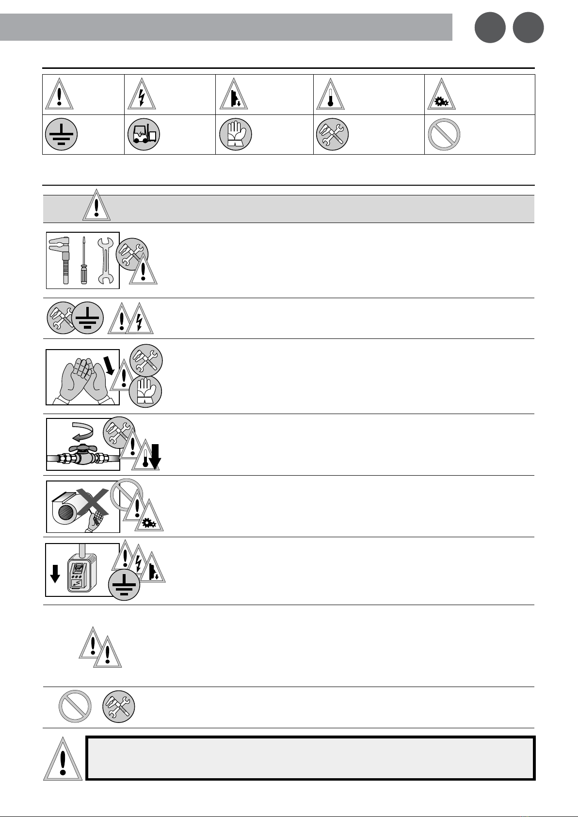
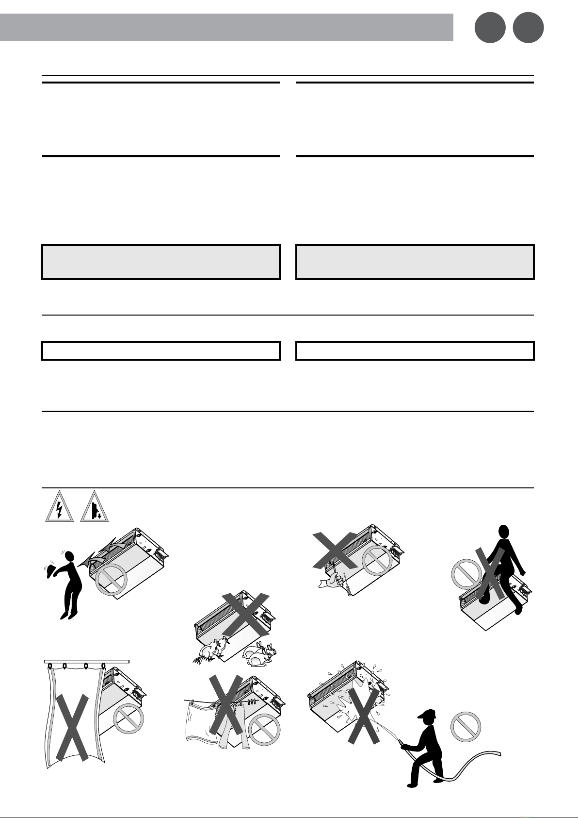
Prestare particolare attenzione alle norme d’uso accompagnate dalle
scritte “PERICOLO” o “ATTENZIONE” in quanto, se non osservate, possono
causare danno all’unità e/o a persone e cose.
Per anomalie non contemplate da questo libretto, interpellare
tempestivamente il Servizio Assistenza di zona.
Assicurarsi che questo libretto accompagni sempre l’unità.
Il libretto costituisce parte integrante ed essenziale del prodotto e dovrà
essere consegnato all’utilizzatore.
Se l’unità dovesse essere venduta, o trasferita ad altro proprietario,
assicurarsi sempre che il libretto accompagni l’unità in modo che possa
essere consultato dal nuovo proprietario e/o dall’installatore.
Il costruttore declina ogni responsabilità per qualsiasi danno dovuto ad un
uso improprio dell’unità, ad una lettura parziale o superficiale delle
informazioni contenute in libretto.
I dati tecnici, le caratteristiche estetiche, i componenti e gli accessori
riportati nel presente libretto non sono impegnativi. Il costruttore si riserva la
facoltà di apportare in qualsiasi momento tutte le modifiche ritenute
necessarie per il miglioramento del proprio prodotto.
I riferimenti a leggi, normative o regole tecniche citate nel presente libretto
sono da intendersi a puro titolo informativo e riferiti alla data di stampa dello
stesso. L’entrata in vigore di nuove disposizioni o di modifiche a quelle vigenti
non costituirà motivo di obbligo alcuno del costruttore nei confronti di terzi.
Il costruttore è responsabile della conformità del proprio prodotto alle leggi,
direttive e norme di costruzione vigenti al momento della
commercializzazione. La conoscenza e l’osservanza delle disposizioni
legislative e delle norme inerenti la progettazione degli impianti,
l’installazione, l’esercizio e la manutenzione sono ad esclusivo carico, per le
rispettive competenze, del progettista, dell’installatore e dell’utente.
ATTENZIONE! E' importante verificare che il progetto e l’installazione siano
conformi alle norme vigenti (Norme EN, Norme di sicurezza, Regolamenti
locali) e siano approvati, quando previsto, dagli enti competenti al controllo
Store this manual in a dry location to avoid deterioration, as they must be
kept for at least 10 years for any future reference.
All the information in this manual must be carefully read and understood: as
they’ll be all very useful for both safe installation and proper use &
maintenance operations.
Pay particular attention to the operating norms marked with “DANGER” or
“WARNING” signals as their disrepect can cause damage to the unit and/or
person or objects.
For any malfunctions not mentioned in this manual, contact the local After
sales Service immediately.
Always keep this handbook with the unit.
This manual is an integral and essential part of the product and must be
given to the user.
Should the unit be sold or transferred to another owner, please ensure that
the manual remains with the unit for use by the new owner and/or installer.
The Manufacturer declines all responsibility for any damage whatsoever
caused by improper use of the unit, and a partial or superficial acquaintance
with the information contained in this manual.
The technical data, styling characteristics, components and accessories
reported in this manual are not binding. The Manufacturer reserves the right
to make changes, at any time, that are considered necessary to improve
the product.
The lawful references, standards or technical rules mentioned in this manual
are presented merely for the sake of information and should be considered
valid as of the date this manual is printed. If new regulations or amendments
to current laws go into effect, this will not obligate the Manufacturer in any
way with regard to others.
The Manufacturer is responsible for ensuring that its product conforms to the
laws, directives and construction standards in force at the time the product is
sold. Knowledge and compliance with legal regulations and standards
regarding plant design, installation, operation and maintenance are the
exclusive responsibility, for the respective competencies, of the designer,
installer and user.
WARNING! It is important to verify that the design and installation conform
with current standards.
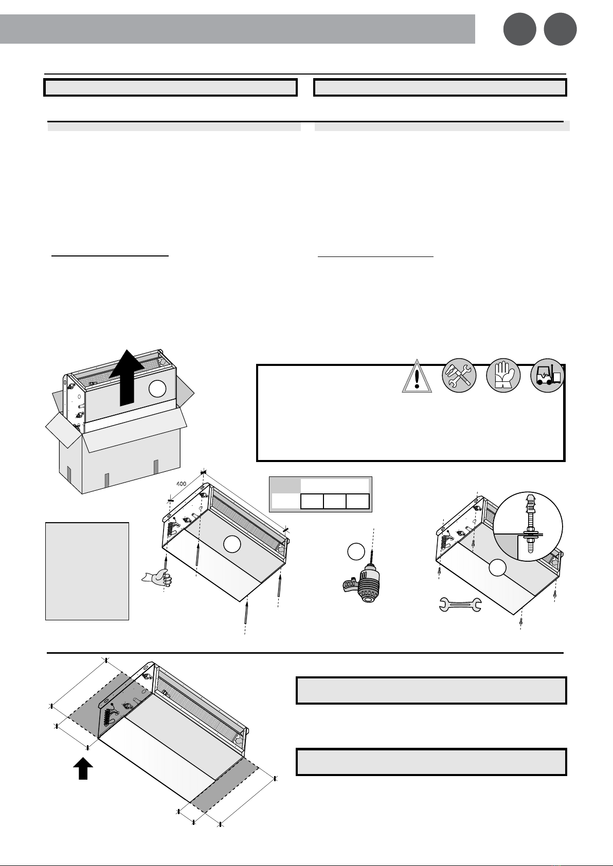
DATI TECNICI ED ASSORBIMENTO ELETTRICO:
Fare riferimento ai valori/dati riportati
sull’etichetta matricolare applicata sull’unità.
TECHNICAL DATA AND ELECTRICAL ABSORPTION:
Refer to values/data as mentioned
on the unit's label.
Dichiariamo, sotto la nostra esclusiva responsabilità, che la macchina in
oggetto è:
Unità per il riscaldamento, condizionamento, ventilazione e trattamento
dell’aria di ambienti civili, residenziali, commerciali ed industriali, marchiata
CE, conforme alle direttive Europee ed Internazionali di sicurezza.
L’unità è conforme a:
-2006/42/CE Direttiva Macchine (ex 98/37/CE ; ex 89/392/CEE e modifiche
91/368/CEE - 93/44/CEE - 93/68/CEE)
-2006/95/CE Direttiva Bassa Tensione (ex 73/23/CEE)
-2004/108/CE Direttiva Compatibilità Elettromagnetica (ex EMC/89/336/CEE)
-97/23/CEE come da Art.3.3 o Art.1.3.6 Direttiva Sistemi in Pressione (PED)
Unità costruita e collaudata in conformità alle seguenti alle seguenti
Direttive:
92/31/CEE – 92/59/CEE
e alle seguenti Normative:
EN/292/1 – EN/292/2
– EN/294 – EN/55014/1 (+A1) (+A2) – EN/55014/2 (+A1) (+A2) – EN/61000/3/2 (+A1)
(+A2) – EN/61000/3/3 – EN/60555/2 – EN/60204/1 – EN/62233 – EN/60335/1 (+A1)
(+A11) (+A12) (+A13) (+A14) (+A15) – EN/60335/2/40 (+A11) (+A12) (+A1) (+A2)
(+A13) e loro emendamenti.
La Direzione Generale
We declare under own responsability that the above equipment
complies is:
Unit for heating, conditioning, ventilation and air treatment in civil,
residential, commercial and industrial environments, CE branded in
accordance with European and International security directives.
The unit is in accordance with:
-2006/42/CE Machine Directive (ex 98/37/CE ; ex 89/392/CEE and amandments
91/368/CEE - 93/44/CEE - 93/68/CEE)
-2006/95/CE Low Voltage Directive (ex 73/23/CEE)
-2004/108/CE Electromagnetic Compatibility Directive (ex. EMC/89/336/CEE)
-97/23/CEE see Art.3.3 or Art.1.3.6 Pressure Equipment Directive (PED)
Unit manufactured and tested according to the following to the following
Directives: 92/31/CEE – 92/59/CEE and the following Standards Standards:
EN/292/1 – EN/292/2 – EN/294 – EN/55014/1 (+A1) (+A2) – EN/55014/2 (+A1) (+A2) –
EN/61000/3/2 (+A1) (+A2) – EN/61000/3/3 – EN/60555/2 – EN/60204/1 – EN/62233 –
EN/60335/1 (+A1) (+A11) (+A12) (+A13) (+A14) (+A15) – EN/60335/2/40 (+A11)
(+A12) (+A1) (+A2) (+A13) and related amendments.
General Management
DICHIARAZIONE CE DI CONFORMITÀ
CE
CONFORMITY DECLARATION
No.
DCF-2502-61026001-R04
Costruttore
Manufacturer
BPS S.r.l.
Zona Industriale Biban, 56 - IT 31030 Carbonera – TREVISO (ITALY)
Tel. +39 0422-445363 r.a. - Fax +39 0422-398646 - www.bpstecnologie.com - info@bpstecnologie.com
Marchio commerciale delle unità
Trade mark of the units
BPS serie CPME
Modelli - Taglie
Models - Sizes
CPME 122 – 132 – 142 – 222 – 232 – 242 – 322 – 332 – 342
CPME 124 – 134 – 224 – 234 – 324 – 334 ; CPME 125 – 135 – 225 – 235 – 325 – 335
Versioni
Versions
Tutte – All (Z1 – Z2 – Z21 – Z22 – P1 – P2 – P21 – P22 – K1 – K2 – K21 – K22)
Accessori - Opzioni - Varianti
Accessories - Options - Variants
Tutti – All (VL… – PMP – MS – MV – MB-2T/4T – MRA1/2 – MRE(230V/400V) – etc.)
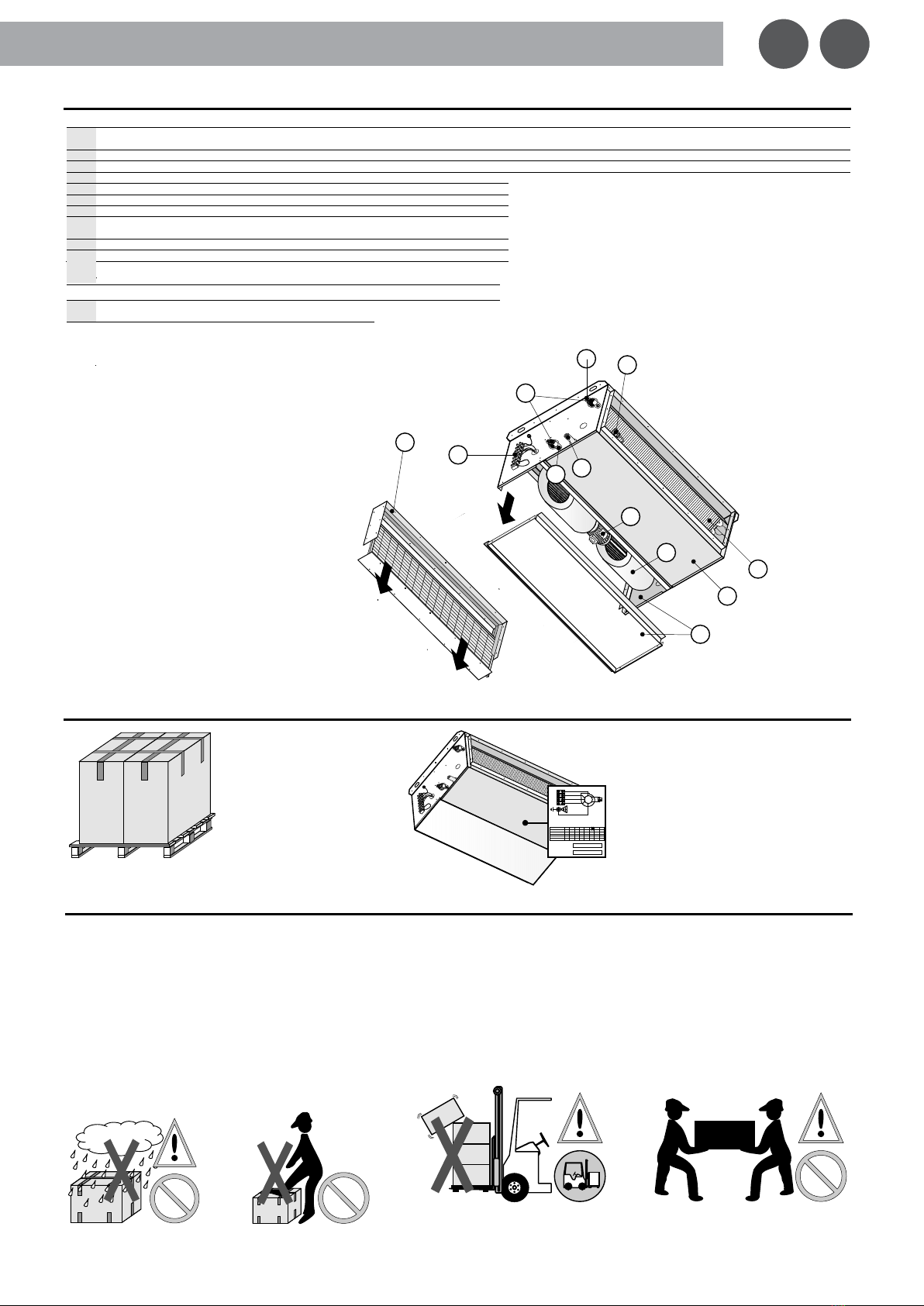
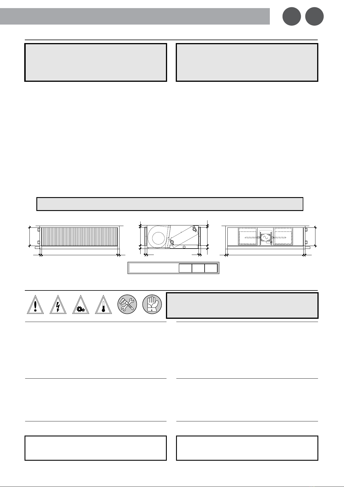
Tipo di unità
Unità Canalizzabili Modulari Piatte/Medie con motore Brushless
(EC), ventilatore centrifugo e batteria ad acqua.
Type of the unit
Modular Terminal Units Slim/Medium with Brushless motor (EC),
centrifugal fan and water coil.
Descrizione Prodotto
Unità per il riscaldamento, condizionamento, ventilazione e
trattamento dell’aria di ambienti civili, residenziali, commerciali
ed industriali, marchiata CE, conforme alle direttive Europee ed
Internazionali di sicurezza.
Product Description
Unit for heating, conditioning, ventilation and air treatment in
civil, residential, commercial and industrial environments, CE
branded in accordance with European and International
security directives.
-2006/42/CE Direttiva Macchine
(ex 98/37/CE, ex 89/392/CEE ed emendamenti 91/368/CEE, 92/59/CEE,
93/44/CEE, 93/68/CEE)
-LVD 2014/35/UE Direttiva Bassa Tensione
(ex 2006/95/CE, ex 73/23/CEE)
-EMC 2014/30/UE Direttiva Compatibilità Elettromagnetica
(ex 2004/108/CE, ex EMC/89/336/CEE ed emendamento 92/31/CEE)
-
97/23/CEE Direttiva Sistemi in Pressione (PED), come da Art.3.3 o Art.1.3.6
-
ErP 2009/125/CE Direttiva Prodotti connessi all’uso dell’Energia
-RoHs 2011/65/UE Direttiva Restrizione sostanze Pericolose
(ex (2002/95/CE)
-
RAEE 2002/96/CE (o WEEE) Direttiva Rifiuti da Apparecchiature Elettriche ed
Elettroniche, come da Art.2 Allegati 1A, 1B ed emandamento 2003/108/CE
(non applicabilità per i componenti di impianti ed unità fisse installati da installatore qualificato)
-
REACH n°1907/2006, Regolamento dell’Unione Europea rif. Registrazione,
Valutazione, Autorizzazione e Restrizione delle Sostanze Chimiche
-2006/42/CE Machine Directive
(ex 98/37/CE, ex 89/392/CEE and amendments 91/368/CEE, 92/59/CEE, 93/44/CEE,
93/68/CEE)
-LVD 2014/35/UE Low Voltage Directive
(ex 2006/95/CE, ex 73/23/CEE)
-EMC 2014/30/UE Electromagnetic Compatibility Directive
(ex 2004/108/CE, ex EMC/89/336/CEE and amendment 92/31/CEE)
-
97/23/CEE Pressure Equipment Directive (PED), see Art.3.3 or Art.1.3.6
-ErP 2009/125/CE Energy related Products Directive
-
RoHs 2011/65/UE Restriction of Hazardous Substances Directive
(ex (2002/95/CE)
-
WEEE 2002/96/CE (or RAEE), Waste of Electric and Electronic Equipment
Directive see Art.2 Attachments 1A, 1B and amendment 2003/108/CE
(not applicable to components of systems and fixed units installed by qualified installer)
-
REACH n°1907/2006, European Union Regulation ref. Registration,
Evaluation, Authorization and Restriction of Chemicals
Unità costruita e collaudata in conformità alle seguenti Normative:
-EN/55014/1 (+A1) (+A2) – EN/55014/2 (+A1) (+A2) –
EN/61000/3/2 (+A1) (+A2) – EN/61000/3/3 – EN/60555/2 –
EN/60204/1 – EN/62233 – EN/60335/1 (+A1) (+A11) (+A12)
(+A13) (+A14) (+A15) – EN/60335/2/40 (+A11) (+A12) (+A1)
(+A2) (+A13) e loro emendamenti.
-UNI/EN/ISO/12100-1:2005 (ex EN/292/1) – UNI/EN/ISO/12100-
2:2005 (ex EN/292/2) – UNI/EN/ISO/13857:2008 (ex EN/294)
Unit manufactured and tested according to the following Standards:
-EN/55014/1 (+A1) (+A2) – EN/55014/2 (+A1) (+A2) –
EN/61000/3/2 (+A1) (+A2) – EN/61000/3/3 – EN/60555/2 –
EN/60204/1 – EN/62233 – EN/60335/1 (+A1) (+A11) (+A12)
(+A13) (+A14) (+A15) – EN/60335/2/40 (+A11) (+A12) (+A1)
(+A2) (+A13) and related amendments.
-UNI/EN/ISO/12100-1:2005 (ex EN/292/1) – UNI/EN/ISO/12100-
2:2005 (ex EN/292/2) – UNI/EN/ISO/13857:2008 (ex EN/294)
Luogo/Data di emissione
Issue place/date
Data di scadenza
Expiry date
Salvo modifiche sul prodotto od obbligo di recepire nuove direttive e/o norme e/o loro emendamenti
Unless modifications on the product or requirement to comply with new directives and/or norms and/or related amendments
TREVISO,
10 – 06 – 2016 09 – 06 – 2021
SERVIZIO CERTIFICAZIONI – TREVISO (ITALY)
R.E.A. TV n. 260185 - Mecc. Estero TV n. 038885
Capitale Sociale € 119.000,00 i.v.
C.F. e P.I.V.A. IT 03302570266
il Responsabile a costituire il fascicolo tecnico e a redigere la dichiarazione CE
the Responsible to constitute the technical file and to draw the EC declaration
Andrea SCHIAVON
(President of CdA)
Dichiarazione Conformità – Conformity Declaration