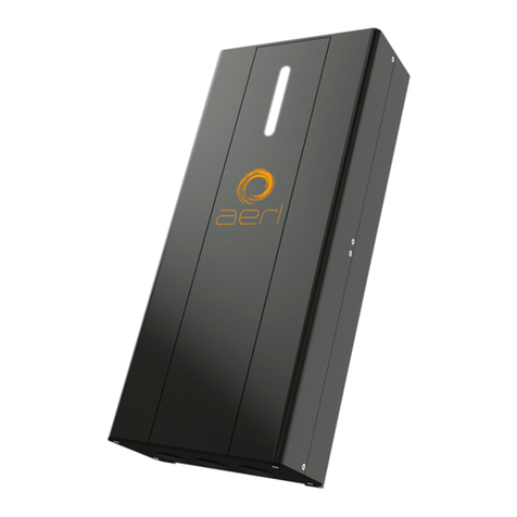
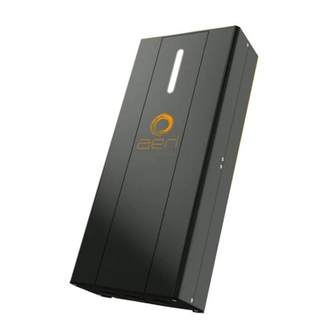
aerl COOLMAX SR User manual

aerl
COMMS MANUAL
COOLMAX SR
Australian Energy Research Laboratories, Pty.Ltd
AER07.004 – Version G2 v9
13th January 2016
COOLMAX SR MAXIMIZER
WALLMOUNT
Communications User Manual
Models
SRMVW
SRHVW

aerl
COMMS MANUAL
COOLMAX SR
Australian Energy Research Laboratories, Pty.Ltd
AER07.004 – Version G2 v9
13th January 2016
1 of 21
TABLE OF CONTENTS
Section
Number
Topic
Page
Number
1Product Warranty................................................................................................3
2Wiring...................................................................................................................4
3 Modbus Communications ..................................................................................5
3.1 Overview......................................................................................................................... 5
3.2 Modbus Network Topology.............................................................................................. 5
3.3 Modbus Wiring................................................................................................................ 6
3.4 Shielding......................................................................................................................... 7
3.5 Modbus Termination........................................................................................................ 7
3.6 Modbus Memory Map (Discrete Inputs) .......................................................................... 7
4 Can Communications .......................................................................................16
4.1 CAN Network Topology................................................................................................. 16
4.2 CAN Wiring................................................................................................................... 17
4.3 Shielding....................................................................................................................... 18
4.4 CAN Termination........................................................................................................... 18
5APPENDIX A– MODBUS Communications ProtocolError! Bookmark not defined.
5.1 Overview......................................................................................................................... 5
5.2 Modbus Memory Map (Discrete Inputs) .......................................................................... 7
6APPENDIX B – CAN Communications Protocol... Error! Bookmark not defined.
6.1 Overview....................................................................................................................... 19
6.2 COOLMAX SR Broadcast Messages ............................................................................ 20
6.3 COOLMAX SR Command Messages............................................................................ 21
S

aerl
COMMS MANUAL
COOLMAX SR
Australian Energy Research Laboratories, Pty.Ltd
AER07.004 – Version G2 v9
13th January 2016
2 of 21
This Installation Manual contains important safety information and Installation instructions for the AERL COOLMAX
SR MAXIMIZER Wall Mount MPPT.
The following symbols are used throughout this user manual to indicate ideal Installation methods, potential
dangerous conditions and important operational information.
About this Manual
This User Manual provides detailed installation and usage instructions for the COOLMAX SR unit. It
is recommended that all of the Instructions and Cautions in this User Manual be read before begin-
ning installation.
Only qualified electricians and technicians should install the COOLMAX SR System. This manual is
intended for all Installation technicians and the system owner.
Do not disassemble or attempt to repair the COOLMAX SR unit unless you are a qualified technician
and have authority in writing from AERL to do so.
AERL will not be held responsible in any way for the mishandling of this product or for installation
of the product in a manner that does not follow the instructions in this manual or as advised by an
AERL technician.
Important
Indicates information that must be followed to ensure proper operation of the COOLMAX SR unit
Indicates a critical procedure for the safe Installation of the COOLMAX SR unit. Use extreme caution
when performing this task.
Caution
Important
Important Safety Information

aerl
COMMS MANUAL
COOLMAX SR
Australian Energy Research Laboratories, Pty.Ltd
AER07.004 – Version G2 v9
13th January 2016
3 of 21
1PRODUCT WARRANTY
1. AERL warrants that the Product will be free from manufacturing defects for a period of 24
months from the date of dispatch of the products by AERL to the customer.
2. The Products technical specifications are contained within the Product Datasheet. The
Product will conform to the technical specifications contained in the Product Datasheet at the
time of dispatch of the Products to the Customer. If the technical specifications as contained
in the Product Datasheet are not met, AERL will repair, replace the Product, or refund the
amount paid by the Customer in relation to the Product at the Customers option. AERL is
under no obligation to provide assistance or advice to the Customer in relation to the
technical specifications.
3. The Products must be installed in strict accordance with the Installation Recommendations
listed in this Manual.
4. In no event will AERL be liable for:
a) any loss or damage which the Customer suffers arising from, or caused or contributed to by,
the Customer's negligence or the negligence of the Customer's agents or servants; and
b) special, indirect or consequential loss or damage as a result of a breach by the Customer of
these Standard Terms including, without limitation, loss of profits or revenue, personal injury,
death, property damage and the costs of any substitute Products which the Customer
obtains.
5. The Product is not covered for damage occurring due to water, including but not limited to
condensation, moisture damage and other forms of precipitation.
6. The Product is not covered for damage occurring due to the Product being incorrectly
installed or installed in a manner not in accordance with the Installation Recommendations
listed in the Product Manual.
7. The Product is not covered for damage occurring due to failure on the part of the customer to
operate the product in accordance with the technical specifications as listed in the Product
Datasheet.
8. The Product is not covered for damage occurring due to lightning.
9. The Product is not covered for situations where it is used in a manner not specifically outlined
in the Product Manual.
10. If any provision in this document is invalid or unenforceable this document will remain otherwise
in full force apart from such provision, which will be deemed deleted
Disclaimer:
Australian Energy Research Laboratories Pty Ltd, its affiliates, agents, and employees, and all persons acting on its
or their behalf (collectively, “AERL”):
a) Disclaim any and all liability for any errors, inaccuracies or incompleteness contained in any datasheet or in any
other disclosure relating to any product
b) Assumes no responsibility or liability for loss or damage whether direct, indirect, consequential or inci-dental,
which might arise out of use of such information. The use of any such information will be entirely at the user's risk.
c) Reserves the right to change any AERL product, product specifications and data without notice to im-prove
reliability, function or design or otherwise.
Notice of Copyright
AERL COOMAX SR MPPT Solar Charge Controller User Manual Copyright ⓒ2016 all rights reserved. AERL
reserves the right to revise this document and to periodically make changes to the content.

aerl
COMMS MANUAL
COOLMAX SR
Australian Energy Research Laboratories, Pty.Ltd
AER07.004 – Version G2 v9
13th January 2016
4 of 21
2WIRING
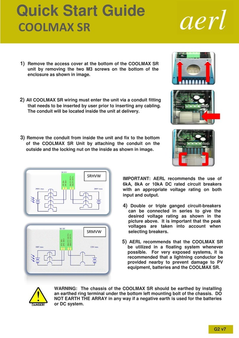
Remove the access cover at the bottom of the COOLMAX SR to install cabling. This is done by
removing the two M3 countersunk hex screws on the bottom of the enclosure at the front as shown
below in Figure 1.
Figure 1: Removal of the Access Panel
Important: All COOLMAX SR wiring must enter the unit via a 40mm conduit
fitting at the bottom of the unit. Drilling holes into the unit to make any other
cable entry point will void the unit’s warranty.
CAUTION: When connecting an external device to any of the COOLMAX SR
communication ports (ie. USB, Modbus RS485 or CAN Bus ports) a suitable
isolator adapter must be used to prevent any possible damage occurring to
the controller and system. Failure to use an isolator adapter in these
circumstances will void customer warranty.

aerl
COMMS MANUAL
COOLMAX SR
Australian Energy Research Laboratories, Pty.Ltd
AER07.004 – Version G2 v9
13th January 2016
5 of 21
3MODBUS COMMUNICATIONS
3.1 OVERVIEW
Hardware
The Modbus hardware interface used is compatible with the Modbus RTU standard. The supported bit
rates (bits per second) is 9600 bps.
Software
All measurement data is transmitted using IEEE single-precision 32-bit format (IEEE 754) with most
significant byte (MSB) sent first.
Modbus Address
The Modbus address is a single byte field, valid address ranges from 1 to 128.
3.2 MODBUS NETWORK TOPOLOGY
Multiple COOLMAX SR units can exist on the same Modbus and this can be connected to other
networks using a Modbus-Ethernet Bridge adaptor.
The Modbus is structured as a linear network, with short stubs branching from 'T' connectors on the
main bus backbone to each device. The Modbus data lines must be terminated at each end of the
main bus with 120 Ω resistors between the Modbus-A and Modbus-B signals.
A simple method of implementing the 'T' junction is shown in Figure . The in and out wire of each
Modbus line are twisted together and screwed into the appropriate terminal on the Modbus connector,
as shown in Figure 4. The Modbus connector is then connected into the COOLMAX SR Modbus
connector socket as shown in Figure 5.
Figure 2 – Modbus Wiring Diagram

aerl
COMMS MANUAL
COOLMAX SR
Australian Energy Research Laboratories, Pty.Ltd
AER07.004 – Version G2 v9
13th January 2016
6 of 21
Figure 3 – Modbus Connector (6-Way Screw Terminal)
3.3 MODBUS WIRING
The Modbus data lines (Modbus-A and Modbus-B) must be implemented with twisted-pair wire for
proper data integrity. The wire should have a characteristic impedance of 120 Ω.
Power should also be provided along the Modbus cable, ideally with another twisted pair to
minimise noise pickup. An overall shield can also be advantageous.
Standard CAT5 network cabling (which has an impedance of 100 Ω) can be used, but may become
unreliable in longer networks or in the presence of electrical noise from DC/DC converters and other
electrical devices in the system.
Modbus Connector Socket
Important: The recommended choice of cable is 7mm DeviceNet Modbus 'thin'
cable, with 24 AWG (data) + 22 AWG (power) twisted pairs and a braided shield.
Using this cable will result in a robust installation.
B GND A
Figure 4 – Modbus Connector
Figure 5 – Modbus Connector Socket

aerl
COMMS MANUAL
COOLMAX SR
Australian Energy Research Laboratories, Pty.Ltd
AER07.004 – Version G2 v9
13th January 2016
7 of 21
3.4 SHIELDING
Correct shielding practice is important for error free communications. Incorrect shielding can cause
more interference than unshielded cables would experience. Shields should be linked between
each wire segment along the network but only grounded in one place. The following paragraphs
explain how to achieve this.
The shield should be wired through the entire network independently of the ground and connected
to ground at the end of the network and nowhere else in the network. This is shown at the right
hand end of the example network in Figure 2.
3.5 MODBUS TERMINATION
A 120 Ω resistor needs to be wired between the Modbus-A and Modbus-B lines at either end of the
linear network in order to terminate both ends of the network. At the far end of the network the
resistor can be simply installed into the last terminal block.
If no Modbus-Ethernet Bridge adapter is present on the network the same terminal block style
termination can be made on the other end of the network. However, if a Modbus-Ethernet Bridge
adapter is present on the network, it can be used to terminate the network by wiring a termination
resistor across Modbus-A and Modbus-B on the unused header.
3.6 MODBUS MEMORY MAP (DISCRETE INPUTS)
Single−Bit (Read−Only)
Returns : 0 to 255 (byte data type) 0x00 to 0xFF (i.e. 8 Bits)
Notes : When a request is sent to read a discrete input, a byte is returned containing the values of 8
consecutive inputs, with the addressed input as the LSB. If the returned input quantity is not a multiple
of 8 bits, then the final data byte is padded with zeros.
Memory
Offset
Input Address
Description
Input
Range
Data
Range
Read/Write
Comment
−
10000
−
−
−
−
−
0
10001
ACTIVE EVENTS
System Power
Bit
0 or 1
Read−Write
0 Event
Cleared
1 Event
Triggered
1
10002
ACTIVE EVENTS
Low Out Voltage
Warning
Bit
0 or 1
Read−Write
0 Event
Cleared
1 Event
Triggered
2
10003
ACTIVE EVENTS
Low Out Voltage Fault
Bit
0 or 1
Read−Write
0 Event
Cleared
1 Event
Triggered
3
10004
ACTIVE EVENTS
Low Out Voltage
Gen−Set
Bit
0 or 1
Read−Write
0 Event
Cleared
1 Event
Triggered
4
10005
ACTIVE EVENTS
High Out Voltage Fault
Bit
0 or 1
Read−Write
0 Event
Cleared
1 Event
Triggered
Important

aerl
COMMS MANUAL
COOLMAX SR
Australian Energy Research Laboratories, Pty.Ltd
AER07.004 – Version G2 v9
13th January 2016
8 of 21
5
10006
ACTIVE EVENTS
High Out Current Fault
Bit
0 or 1
Read−Write
0 Event
Cleared
1 Event
Triggered
6
10007
ACTIVE EVENTS
High Discharge
Current Fault
Bit
0 or 1
Read−Write
0 Event
Cleared
1 Event
Triggered
7
10008
ACTIVE EVENTS
High Battery
Temperature Fault
Bit
0 or 1
Read−Write
0 Event
Cleared
1 Event
Triggered
8
10009
ACTIVE EVENTS
Input Breaker Open
Bit
0 or 1
Read−Write
0 Event
Cleared
1 Event
Triggered
9
10010
ACTIVE EVENTS
Output Breaker Open
Bit
0 or 1
Read−Write
0 Event
Cleared
1 Event
Triggered
10
10011
ACTIVE EVENTS
Temperature Sensor
Fault
Bit
0 or 1
Read−Write
0 Event
Cleared
1 Event
Triggered
11
10012
ACTIVE EVENTS
Negative PV Current
Shutdown
Bit
0 or 1
Read−Write
0 Event
Cleared
1 Event
Triggered
Memory
Offset
Input Address
Description
Input
Range
Data
Range
Read/Write
Comment
12
10013
ACTIVE EVENTS
High PV Current
Shutdown
Bit
0 or 1
Read−Write
0 Event
Cleared
1 Event
Triggered
13
10014
ACTIVE EVENTS
High PV Voltage
Shutdown
Bit
0 or 1
Read−Write
0 Event
Cleared
1 Event
Triggered
14
10015
ACTIVE EVENTS
High Output Current
Shutdown
Bit
0 or 1
Read−Write
0 Event
Cleared
1 Event
Triggered
15
10016
ACTIVE EVENTS
High Output Voltage
Shutdown
Bit
0 or 1
Read−Write
0 Event
Cleared
1 Event
Triggered
16
10017
ACTIVE EVENTS
Heat−Sink
Temperature Too High
Bit
0 or 1
Read−Write
0 Event
Cleared
1 Event
Triggered
17
10018
ACTIVE EVENTS
Fan Fault
Bit
0 or 1
Read−Write
0 Event
Cleared

aerl
COMMS MANUAL
COOLMAX SR
Australian Energy Research Laboratories, Pty.Ltd
AER07.004 – Version G2 v9
13th January 2016
9 of 21
1 Event
Triggered
18
10019
ACTIVE EVENTS
Log File Full
Bit
0 or 1
Read−Write
0 Event
Cleared
1 Event
Triggered
19
10020
ACTIVE EVENTS
Solar Panel Missing
Bit
0 or 1
Read−Write
0 Event
Cleared
1 Event
Triggered
20
10021
ACTIVE EVENTS
Config Value
Out−Of−Range
Bit
0 or 1
Read−Write
0 Event
Cleared
1 Event
Triggered
21
10022
ACTIVE EVENTS
(Not Used)
Bit
0 or 1
Read−Write
Reserved
22
10023
ACTIVE EVENTS
(Not Used)
Bit
0 or 1
Read−Write
Reserved
23
10024
ACTIVE EVENTS
(Not Used)
Bit
0 or 1
Read−Write
Reserved
24
10025
ACTIVE EVENTS
(Not Used)
Bit
0 or 1
Read−Write
Reserved
25
10026
ACTIVE EVENTS
(Not Used)
Bit
0 or 1
Read−Write
Reserved
26
10027
ACTIVE EVENTS
(Not Used)
Bit
0 or 1
Read−Write
Reserved
27
10028
ACTIVE EVENTS
(Not Used)
Bit
0 or 1
Read−Write
Reserved
Memory
Offset
Input Address
Description
Input
Range
Data
Range
Read/Write
Comment
28
10029
ACTIVE EVENTS
(Not Used)
Bit
0 or 1
Read−Write
Reserved
29
10030
ACTIVE EVENTS
(Not Used)
Bit
0 or 1
Read−Write
Reserved
30
10031
ACTIVE EVENTS
(Not Used)
Bit
0 or 1
Read−Write
Reserved
31
10032
ACTIVE EVENTS
(Not Used)
Bit
0 or 1
Read−Write
Reserved
32
10033
STATUS –
Configuration
Factory Config CRC
Bit
0 or 1
Read−Only
0 CRC
Invalid
1 CRC
Valid
33
10034
STATUS –
Configuration
Factory Config Check
Bit
0 or 1
Read−Only
0 Check
Failed
1 Check
Passed
34
10035
STATUS –
Configuration
User Config CRC
Bit
0 or 1
Read−Only
0 CRC
Invalid
1 CRC
Valid
35
10036
STATUS –
Configuration
User Config Check
Bit
0 or 1
Read−Only
0 Check
Failed
1 Check
Passed

aerl
COMMS MANUAL
COOLMAX SR
Australian Energy Research Laboratories, Pty.Ltd
AER07.004 – Version G2 v9
13th January 2016
10 of 21
36
10037
STATUS –
Configuration
Event Config CRC
Bit
0 or 1
Read−Only
0 CRC
Invalid
1 CRC
Valid
37
10038
STATUS –
Configuration
Event Config Check
Bit
0 or 1
Read−Only
0 Check
Failed
1 Check
Passed
38
10039
STATUS –
Configuration
Telemetry Config CRC
Bit
0 or 1
Read−Only
0 CRC
Invalid
1 CRC
Valid
39
10040
STATUS –
Configuration
Telemetry Config
Check
Bit
0 or 1
Read−Only
0 Check
Failed
1 Check
Passed
40
10041
STATUS – Statistics
(Not Used)
Bit
0 or 1
Read−Only
Reserved
41
10042
STATUS – Statistics
(Not Used)
Bit
0 or 1
Read−Only
Reserved
42
10043
STATUS – Statistics
(Not Used)
Bit
0 or 1
Read−Only
Reserved
43
10044
STATUS – Statistics
(Not Used)
Bit
0 or 1
Read−Only
Reserved
44
10045
STATUS – Statistics
(Not Used)
Bit
0 or 1
Read−Only
Reserved
Memory
Offset
Input Address
Description
Input
Range
Data
Range
Read/Write
Comment
45
10046
STATUS – Statistics
(Not Used)
Bit
0 or 1
Read−Only
Reserved
46
10047
STATUS – Statistics
(Not Used)
Bit
0 or 1
Read−Only
Reserved
47
10048
STATUS – Statistics
(Not Used)
Bit
0 or 1
Read−Only
Reserved
48
10049
STATUS – Flags
(Not Used)
Bit
0 or 1
Read−Only
Reserved
49
10050
STATUS – Flags
(Not Used)
Bit
0 or 1
Read−Only
Reserved
50
10051
STATUS – Flags
(Not Used)
Bit
0 or 1
Read−Only
Reserved
51
10052
STATUS – Flags
(Not Used)
Bit
0 or 1
Read−Only
Reserved
52
10053
STATUS – Flags
(Not Used)
Bit
0 or 1
Read−Only
Reserved
53
10054
STATUS – Flags
(Not Used)
Bit
0 or 1
Read−Only
Reserved
54
10055
STATUS – Flags
(Not Used)
Bit
0 or 1
Read−Only
Reserved

aerl
COMMS MANUAL
COOLMAX SR
Australian Energy Research Laboratories, Pty.Ltd
AER07.004 – Version G2 v9
13th January 2016
11 of 21
55
10056
STATUS – Flags
(Not Used)
Bit
0 or 1
Read−Only
Reserved
56
10057
STATUS – Telemetry
(Not Used)
Bit
0 or 1
Read−Only
Reserved
57
10058
STATUS – Telemetry
(Not Used)
Bit
0 or 1
Read−Only
Reserved
58
10059
STATUS – Telemetry
(Not Used)
Bit
0 or 1
Read−Only
Reserved
59
10060
STATUS – Telemetry
(Not Used)
Bit
0 or 1
Read−Only
Reserved
60
10061
STATUS – Telemetry
(Not Used)
Bit
0 or 1
Read−Only
Reserved
61
10062
STATUS – Telemetry
(Not Used)
Bit
0 or 1
Read−Only
Reserved
62
10063
STATUS – Telemetry
(Not Used)
Bit
0 or 1
Read−Only
Reserved
63
10064
STATUS – Telemetry
(Not Used)
Bit
0 or 1
Read−Only
Reserved
64
10065
STATUS –
Communications
(Not Used)
Bit
0 or 1
Read−Only
Reserved
65
10066
STATUS –
Communications
(Not Used)
Bit
0 or 1
Read−Only
Reserved
66
10067
STATUS –
Communications
(Not Used)
Bit
0 or 1
Read−Only
Reserved
67
10068
STATUS –
Communications
(Not Used)
Bit
0 or 1
Read−Only
Reserved
Memory
Offset
Input Address
Description
Input
Range
Data
Range
Read/Write
Comment
68
10069
STATUS –
Communications
(Not Used)
Bit
0 or 1
Read−Only
Reserved
69
10070
STATUS –
Communications
(Not Used)
Bit
0 or 1
Read−Only
Reserved
70
10071
STATUS –
Communications
(Not Used)
Bit
0 or 1
Read−Only
Reserved
71
10072
STATUS –
Communications
(Not Used)
Bit
0 or 1
Read−Only
Reserved
72
10073
STATUS – Flash
(Not Used)
Bit
0 or 1
Read−Only
Reserved
73
10074
STATUS – Flash
(Not Used)
Bit
0 or 1
Read−Only
Reserved
74
10075
STATUS – Flash
(Not Used)
Bit
0 or 1
Read−Only
Reserved
75
10076
STATUS – Flash
(Not Used)
Bit
0 or 1
Read−Only
Reserved
76
10077
STATUS – Flash
(Not Used)
Bit
0 or 1
Read−Only
Reserved
77
10078
STATUS – Flash
Bit
0 or 1
Read−Only
Reserved

aerl
COMMS MANUAL
COOLMAX SR
Australian Energy Research Laboratories, Pty.Ltd
AER07.004 – Version G2 v9
13th January 2016
12 of 21
(Not Used)
78
10079
STATUS – Flash
(Not Used)
Bit
0 or 1
Read−Only
Reserved
79
10080
STATUS – Flash
(Not Used)
Bit
0 or 1
Read−Only
Reserved
80
10081
STATUS – Control
Master / Slave
Bit
0 or 1
Read−Only
0 Device
is Master
1 Device
is Slave
81
10082
STATUS – Control
Active Set−Point Mode
Bit
0 or 1
Read−Only
0 Using
Float
Set−Point
1 Using
Bulk
Set−Point
82
10083
STATUS – Control
Control Mode
Bit
0 or 1
Read−Only
0 MPPT
1 Output
Voltage
2 Input
Voltage
3 Not
Used
83
10084
84
10085
STATUS – Control
(Not Used)
Bit
0 or 1
Read−Only
Reserved
Memory
Offset
Input Address
Description
Input
Range
Data
Range
Read/Write
Comment
85
10086
STATUS – Control
(Not Used)
Bit
0 or 1
Read−Only
Reserved
86
10087
STATUS – Control
(Not Used)
Bit
0 or 1
Read−Only
Reserved
87
10088
STATUS – Control
(Not Used)
Bit
0 or 1
Read−Only
Reserved
88
10089
STATUS – Safety
Shutdown State
Bit
0 or 1
Read−Only
0
Shutdown
1
Operating
89
10090
STATUS – Safety
(Not Used)
Bit
0 or 1
Read−Only
Reserved
90
10091
STATUS – Safety
(Not Used)
Bit
0 or 1
Read−Only
Reserved
92
10093
STATUS – Safety
(Not Used)
Bit
0 or 1
Read−Only
Reserved

aerl
COMMS MANUAL
COOLMAX SR
Australian Energy Research Laboratories, Pty.Ltd
AER07.004 – Version G2 v9
13th January 2016
13 of 21
93
10094
STATUS – Safety
(Not Used)
Bit
0 or 1
Read−Only
Reserved
94
10095
STATUS – Safety
(Not Used)
Bit
0 or 1
Read−Only
Reserved
95
10096
STATUS – Safety
(Not Used)
Bit
0 or 1
Read−Only
Reserved
3.7 MODBUS MEMORY MAP (INPUT REGISTERS)
16−Bit (Register)
Returns : 0 to 65535 (unsigned short data type) 0x0000 to 0xFFFF (i.e. 2 x 8 Bits)
Notes : When a request is sent to read an input register, two bytes are returned for each register.
The result may be stored as an unsigned short data type.
Integers and Floating point values (32−bits) are stored over two registers.
Long values (64−bits) are stored over 4 registers.
Memory
Offset
Register
Address
Description
Register
Range
Data
Range
Read/Write
Comment
−
30000
−
−
−
−
−
0
30001
LIVE TELEMETRY
Product ID
(8 Characters)
16−Bits
0 to 65535
Read−Only
Product ID (Byte 1 − High)
Product ID (Byte 2 − Low)
1
30002
16−Bits
0 to 65535
Read−Only
Product ID (Byte 3 − High)
Product ID (Byte 4 − Low)
2
30003
16−Bits
0 to 65535
Read−Only
Product ID (Byte 5 − High)
Product ID (Byte 6 − Low)
3
30004
16−Bits
0 to 65535
Read−Only
Product ID (Byte 7 − High)
Product ID (Byte 8 − Low)
4
30005
LIVE TELEMETRY
Serial Number
(8 Characters)
16−Bits
0 to 65535
Read−Only
Serial # (Byte 1 − High)
Serial # (Byte 2 − Low)
5
30006
16−Bits
0 to 65535
Read−Only
Serial # (Byte 3 − High)
Serial # (Byte 4 − Low)
6
30007
16−Bits
0 to 65535
Read−Only
Serial # (Byte 5 − High)
Serial # (Byte 6 − Low)
7
30008
16−Bits
0 to 65535
Read−Only
Serial # (Byte 7 − High)
Serial # (Byte 8 − Low)
8
30009
LIVE TELEMETRY
PV Voltage (Volts)
(Float)
16−Bits
0 to 65535
Read−Only
PV Voltage (Byte 1 − High)
PV Voltage (Byte 2 − Low)
9
30010
16−Bits
0 to 65535
Read−Only
PV Voltage (Byte 3 − High)
PV Voltage (Byte 4 − Low)
10
30011
LIVE TELEMETRY
PV Current (Amps)
(Float)
16−Bits
0 to 65535
Read−Only
PV Current (Byte 1 − High)
PV Current (Byte 2 − Low)
11
30012
16−Bits
0 to 65535
Read−Only
PV Current (Byte 3 − High)
PV Current (Byte 4 − Low)
12
30013
LIVE TELEMETRY
Output Voltage (Volts)
(Float)
16−Bits
0 to 65535
Read−Only
Out Voltage (Byte 1 −
High)
Out Voltage (Byte 2 − Low)
13
30014
16−Bits
0 to 65535
Read−Only
Out Voltage (Byte 3 −
High)
Out Voltage (Byte 4 − Low)
14
30015
LIVE TELEMETRY
Output Current (Amps)
(Float)
16−Bits
0 to 65535
Read−Only
Out Current (Byte 1 −
High)
Out Current (Byte 2 − Low)
15
30016
16−Bits
0 to 65535
Read−Only
Out Current (Byte 3 −

aerl
COMMS MANUAL
COOLMAX SR
Australian Energy Research Laboratories, Pty.Ltd
AER07.004 – Version G2 v9
13th January 2016
14 of 21
High)
Out Current (Byte 4 − Low)
16
30017
LIVE TELEMETRY
PV Open−Circuit
Voltage
(Volts)
(Float)
16−Bits
0 to 65535
Read−Only
OC Voltage (Byte 1 −
High)
OC Voltage (Byte 2 − Low)
17
30018
16−Bits
0 to 65535
Read−Only
OC Voltage (Byte 3 −
High)
OC Voltage (Byte 4 − Low)
18
30019
LIVE TELEMETRY
Daily Output Charge
(Ah) (Float)
16−Bits
0 to 65535
Read−Only
Out Charge (Byte 1 −
High)
Out Charge (Byte 2 − Low)
19
30020
16−Bits
0 to 65535
Read−Only
Out Charge (Byte 3 −
High)
Out Charge (Byte 4 − Low)
20
30021
LIVE TELEMETRY
Photovoltaic Power (W)
(Float)
16−Bits
0 to 65535
Read−Only
PV Power (Byte 1 − High)
PV Power (Byte 2 − Low)
21
30022
16−Bits
0 to 65535
Read−Only
PV Power (Byte 3 − High)
PV Power (Byte 4 − Low)
Memory
Offset
Register
Address
Description
Register
Range
Data Range
Read/Write
Comment
22
30023
LIVE TELEMETRY
Case Temperature
(°C) (Float)
16−Bits
0 to 65535
Read−Only
Out Current (Byte 1 − High)
Out Current (Byte 2 − Low)
23
30024
16−Bits
0 to 65535
Read−Only
Out Current (Byte 3 − High)
Out Current (Byte 4 − Low)
24
30025
LIVE TELEMETRY
Active Events
(Uint32)
16−Bits
0 to 65535
Read−Only
Active Events (Byte 1 −
High)
Active Events (Byte 2 −
Low)
25
30026
16−Bits
0 to 65535
Read−Only
Active Events (Byte 3 −
High)
Active Events (Byte 4 −
Low)
26
30027
LIVE TELEMETRY
Status Flags
(UInt64)
16−Bits
0 to 65535
Read−Only
Status Flags (Byte 1 − High)
Status Flags (Byte 2 − Low)
27
30028
16−Bits
0 to 65535
Read−Only
Status Flags (Byte 3 − High)
Status Flags (Byte 4 − Low)
28
30029
16−Bits
0 to 65535
Read−Only
Status Flags (Byte 5 − High)
Status Flags (Byte 6 − Low)
29
30030
16−Bits
0 to 65535
Read−Only
Status Flags (Byte 7 − High)
Status Flags (Byte 8 − Low)
30
30031
LIVE TELEMETRY
Unix Time
(UInt64)
16−Bits
0 to 65535
Read−Only
Unix Time (Byte 1 − High)
Unix Time (Byte 2 − Low)
31
30032
16−Bits
0 to 65535
Read−Only
Unix Time (Byte 3 − High)
Unix Time (Byte 4 − Low)
32
30033
16−Bits
0 to 65535
Read−Only
Unix Time (Byte 5 − High)
Unix Time (Byte 6 − Low)
33
30034
16−Bits
0 to 65535
Read−Only
Unix Time (Byte 7 − High)
Unix Time (Byte 8 − Low)
40
30041
SYSTEM INFO
Hardware Version
(8 Characters)
16−Bits
0 to 65535
Read−Only
Hardware Ver. (Byte 1 −
High)
Hardware Ver. (Byte 2 −
Low)
41
30042
16−Bits
0 to 65535
Read−Only
Hardware Ver. (Byte 3 −
High)
Hardware Ver. (Byte 4 −
Low)
42
30043
16−Bits
0 to 65535
Read−Only
Hardware Ver. (Byte 5 −

aerl
COMMS MANUAL
COOLMAX SR
Australian Energy Research Laboratories, Pty.Ltd
AER07.004 – Version G2 v9
13th January 2016
15 of 21
High)
Hardware Ver. (Byte 6 −
Low)
43
30044
16−Bits
0 to 65535
Read−Only
Hardware Ver. (Byte 7 −
High)
Hardware Ver. (Byte 8 −
Low)
Memory
Offset
Register
Address
Description
Register
Range
Data
Range
Read/Write
Comment
44
30045
SYSTEM INFO
Firmware Version
(8 Characters)
16−Bits
0 to 65535
Read−Only
Firmware Ver. (Byte 1 −
High)
Firmware Ver. (Byte 2 −
Low)
45
30046
16−Bits
0 to 65535
Read−Only
Firmware Ver. (Byte 3 −
High)
Firmware Ver. (Byte 4 −
Low)
46
30047
16−Bits
0 to 65535
Read−Only
Firmware Ver. (Byte 5 −
High)
Firmware Ver. (Byte 6 −
Low)
47
30048
16−Bits
0 to 65535
Read−Only
Firmware Ver. (Byte 7 −
High)
Firmware Ver. (Byte 8 −
Low)
48
30049
SYSTEM INFO
Model Type
(4 Characters)
16−Bits
0 to 65535
Read−Only
Model Type (Byte 1 − High)
Model Type (Byte 2 − Low)
49
30050
16−Bits
0 to 65535
Read−Only
Model Type (Byte 3 − High)
Model Type (Byte 4 − Low)
50
30051
SYSTEM INFO
Product ID
(8 Characters)
16−Bits
0 to 65535
Read−Only
Product ID (Byte 1 − High)
Product ID (Byte 2 − Low)
51
30052
16−Bits
0 to 65535
Read−Only
Product ID (Byte 3 − High)
Product ID (Byte 4 − Low)
52
30053
16−Bits
0 to 65535
Read−Only
Product ID (Byte 5 − High)
Product ID (Byte 6 − Low)
53
30054
16−Bits
0 to 65535
Read−Only
Product ID (Byte 7 − High)
Product ID (Byte 8 − Low)
54
30055
SYSTEM INFO
Serial Number
(8 Characters)
16−Bits
0 to 65535
Read−Only
Serial # (Byte 1 − High)
Serial # (Byte 2 − Low)
55
30056
16−Bits
0 to 65535
Read−Only
Serial # (Byte 3 − High)
Serial # (Byte 4 − Low)
56
30057
16−Bits
0 to 65535
Read−Only
Serial # (Byte 5 − High)
Serial # (Byte 6 − Low)
57
30058
16−Bits
0 to 65535
Read−Only
Serial # (Byte 7 − High)
Serial # (Byte 8 − Low)
58
30059
SYSTEM INFO
Reserved
16−Bits
0 to 65535
Read−Only
Reserved
59
30060
SYSTEM INFO
Reserved
16−Bits
0 to 65535
Read−Only
Reserved
60
30061
SYSTEM INFO
Reserved
16−Bits
0 to 65535
Read−Only
Reserved
61
30062
SYSTEM INFO
Reserved
16−Bits
0 to 65535
Read−Only
Reserved
62
30063
SYSTEM INFO
Reserved
16−Bits
0 to 65535
Read−Only
Reserved
63
30064
SYSTEM INFO
Reserved
16−Bits
0 to 65535
Read−Only
Reserved

aerl
COMMS MANUAL
COOLMAX SR
Australian Energy Research Laboratories, Pty.Ltd
AER07.004 – Version G2 v9
13th January 2016
16 of 21
4 CAN COMMUNICATIONS
4.1 CAN NETWORK TOPOLOGY
Multiple COOLMAX SR units can exist on the same CAN bus and this can be connected to other
networks using a CAN-Ethernet Bridge adaptor.
The CAN bus is structured as a linear network, with short stubs branching from 'T' connectors on
the main bus backbone to each device. The CAN bus data lines must be terminated at each end of
the main bus with 120 Ω resistors between the CAN-H and CAN-L signals.
A simple method of implementing the 'T' junction is shown in Figure 6. The in and out wire of each
CAN line are twisted together and screwed into the appropriate terminal on the CAN connector, as
shown below in Figure 7. This connector plugs into J3 as shown in Figure 8.
Figure 6 - CAN Network Wiring Diagram

aerl
COMMS MANUAL
COOLMAX SR
Australian Energy Research Laboratories, Pty.Ltd
AER07.004 – Version G2 v9
13th January 2016
17 of 21
Figure 7 - CAN Connector (6-Way Screw Terminal)
4.2 CAN WIRING
The CAN data lines (CAN-H and CAN-L) must be implemented with twisted-pair wire for proper
data integrity. The wire should have a characteristic impedance of 120 Ω.
Power should also be provided along the CAN cable, ideally with another twisted pair to minimise
noise pickup. An overall shield can also be advantageous.
The recommended choice of cable is 7mm DeviceNet CAN-Bus 'thin' cable, with 24 AWG (data) +
22 AWG (power) twisted pairs and a braided shield. Using this cable will result in a robust
installation.
Standard CAT5 network cabling (which has an impedance of 100 Ω) can be used, but may become
unreliable in longer networks or in the presence of electrical noise from DC/DC converters and other
electrical devices in the system.
With the access cover removed, three terminal blocks should be visible. The left most terminal block
(J1) is for the alarm output, remote shutdown input, and temperature compensation. The terminal
block (J3) on the right is for the Controller Area Network (CAN). The central terminal block (J2) is
for power in and power out. Figure 8 and Table 1 below show the PIN-outs for these terminals.
Figure 8 - Terminal Board PINout (Looking into Access Port)
Important

aerl
COMMS MANUAL
COOLMAX SR
Australian Energy Research Laboratories, Pty.Ltd
AER07.004 – Version G2 v9
13th January 2016
18 of 21
Signal PIN Assignment
PIN
Assignment
Type
Functional Description
Isolated
J1-1
GND
Analogue input
Temperature compensation thermistor
NO
J1-2
TMPCMP
J1-3
GND
Digital input
Pull these lines together to disable
output of the Maximizer
NO
J1-4
ON/OFF
J1-5
Alarm NO
Clean contact
output
Will close when an alarm is active
YES - 1000V
J1-6
Alarm COM
J2-1
PV IN-
PV PWR IN
Refer to Product datasheet for the
current and voltage limitations
NO
J2-2
PV IN+
J2-3
BATT OUT +
BATT PWR OUT
Refer to Product datasheet for the
current and voltage limitations
NO
J2-4
BATT OUT -
J3-1
CAN +12V
Output power
Power for the CAN bus
YES
J3-2
CAN GND
J3-3
SHIELD
YES
J3-4
CAN H
Digital IO
CAN signals
J3-5
CAN L
J3-6
NC
Table 1 - Signal PIN Assignment
4.3 SHIELDING
Correct shielding practice is important for error free communications. Incorrect shielding can cause
more interference than unshielded cables would experience. Shields should be linked between
each wire segment along the network but only grounded in one place. The following paragraphs
explain how to achieve this.
The shield should be wired through the entire network independently of the ground and connected
to ground at the end of the network and nowhere else in the network. This is shown at the right
hand end of the example network in Figure 6.
4.4 CAN TERMINATION
A 120 Ω resistor needs to be wired between the CAN-H and CAN-L lines at either end of the linear
network in order to terminate both ends of the network. At the far end of the network the resistor can
be simply installed into the last terminal block.
Important

aerl
COMMS MANUAL
COOLMAX SR
Australian Energy Research Laboratories, Pty.Ltd
AER07.004 – Version G2 v9
13th January 2016
19 of 21
If no CAN-Ethernet Bridge adapter is present on the network the same terminal block style
termination can be made on the other end of the network. However, if a CAN-Ethernet Bridge
adapter is present on the network, it can be used to terminate the network by wiring a termination
resistor across CAN-H and CAN-L on the unused header.
OVERVIEW
3.7.1 Hardware
The CAN hardware interface used is compatible with the CAN 2.0B standard. The supported bit
rates (bits per second) are 1 Mbps, 500 kbps (default), 250 kbps, 125 kbps, 100 kbps and 50 kbps.
3.7.2 Software
The CAN protocol uses data frames for most communication. Remote frames are also enabled. All
measurement data is transmitted using IEEE single-precision 32-bit format (IEEE 754) with most
significant byte (MSB) sent first.
Bit Length
1
11
6
8 Bytes
16
2
7
Start
Identifier
Control
Data Field
CRC
Ack
End
Figure 2 - CAN Data Frame
3.7.3 Identifier
The identifier field has been split into two sections for the COOLMAX SR. Bits 10-5 contain the
device identifier and bits 4-0 contains the message identifier associated with that device, as shown
below.
10
5
4
0
DEVICE IDENTIFIER
MESSAGE IDENTIFIER
Figure 3 - CAN Device Identifier Address Format
3.7.4 Data Field
The data field in all frames is fixed at 8 bytes (64 bits) which allows space for two IEEE 754 32-bit
floating point variables as shown in the Figure below. The data field is sent and expected to be
received least significant byte first. This allows a direct overlay of a float[2] array and char[8] array
on a little endian processor.
High float
Low float
seeeeeeee mmmmmmmmmmmmmmmmmmmmmm
^^^^^
63 62 55 54 32
seeeeeeee mmmmmmmmmmmmmmmmmmmmmm
^^^^^
31 30 23 22 0
Figure 4 - Format of a Data Field in a Data Frame
Other manuals for COOLMAX SR
1
This manual suits for next models
2
Table of contents
Other aerl Controllers manuals
Popular Controllers manuals by other brands
gefran
gefran GPC 40-600A Use and installation manual

Skov
Skov DOL 278T Technical manual
Renard-Plus
Renard-Plus TR24 manual
Siko
Siko AG26 Translation of the original installation instructions
Mitsubishi Electric
Mitsubishi Electric Q172CPU Programming manual
NXP Semiconductors
NXP Semiconductors OM5579 quick start guide
