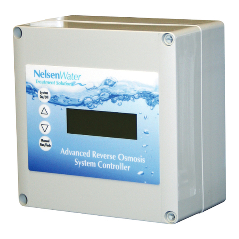
NELSEN WATER NRO ROC-3HE User manual

Nelsen NRO ROC-3HE
System Controller Documentation
Systems with 3 hp Motors and Above

2
Table of Contents
Table of Contents..................................................................................................................................................................................................................................................................Description Page
Specifications, Table 1......................................................................................................................................................................................................................................................................................................1
Schematic, Figure 1..............................................................................................................................................................................................................................................................................................................2
Field Wiring Diagram, Figure 1.1....................................................................................................................................................................................................................................................................3
Controller Overview, Figure 2...............................................................................................................................................................................................................................................................................4
Controller Detail: CPU-4..................................................................................................................................................................................................................................................................................................5
Controller Detail: TB-6.......................................................................................................................................................................................................................................................................................................6
Conductivity Probe Installation, Figure 5..........................................................................................................................................................................................................................................7
Controller Programming: Accessing Hidden Menus, Figure 6....................................................................................................................................................................8
System Start-up w/Permeate Flush..........................................................................................................................................................................................................................................................8
Controller Programming: Program Selections, Table 2.............................................................................................................................................................................................9
Controller Programming: Parameters Explained, Appendix A...................................................................................................................................................... 10-11
Controller Fault Displays................................................................................................................................................................................................................................................................................ 11-12
Controller Programming: Programming Interface Overview...................................................................................................................................................................... 13
Warranty.............................................................................................................................................................................................................................................................................................................................................. 14

1
Table 1 - Specifications
Inputs
Tank level switches (2) Normally-Closed. Can be used with a single level switch.
Inlet pressure switch Normally-Open.
Pretreat lockout switch Normally-Open.
High Pressure switch Normally-Open.
Controller Power 100-240 VAC, 60/50Hz (Switching power supply automatically adjusts)
Permeate Conductivity 0-3000 PPM, 0-6000 μs (standard sensor, CP-1, K=.75)
Feed Conductivity (opt) 0-3000 PPM, 0-6000 μs (standard sensor, CP-1, K=.75)
Output Relay Ratings (relays are fused with a 6A fuse)
Feed Solenoid 0.5A. Voltage is the same as motor/supply voltage.
Flush Solenoid 0.5A. Voltage is the same as motor/supply voltage.
Motor Contactor Coil 0.5A. Voltage is the same as motor/supply voltage.
Motor Contactor
ROC-2XHE-20 20A Definite Purpose Contactor: 3.0 HP @ 208-240V.
ROC-2XHE-40 40A Definite Purpose Contactor: 5.0 HP @ 208-240V.
Circuit Protection
Main/Relay Power Fuse F1 5x20mm 6 Amp Littelfuse 0234006P
Power Supply/CPU Fuse F2 5x20mm 0.125 Amp Littelfuse 0218.125P
Other
Dimensions 7” tall, 7” wide, 4”” deep. Nema 4X Polycarbonate Hinged Enclosure.
Weight 2.7 lb.
Environment 0-50°C, 10-90%RH (non-condensing)

2
Figure 1 - Simplified Schematic

3
Figure 1.1 - Field Wiring Diagram

4
Figure 2 - Controller Overview
Keypad
System ON/OFF,
Up Arrow
Down Arrow
Manual Run, Manual Flush
Supply Power
Connections
Motor
Connections
Terminal Board
CPU4 Board
Conductivity Probe
Connections
Display
(4 line, 20 character)
Clear, concise feedback
on the RO’s status.
Alarm
Display backlight
flashes along with
audible beeper to
indicate alarm condition.

5
Typical Configuration
Figure 3 - Controller Detail: CPU-4
Typical Configuration

6
Figure 4 - Controller Detail: Terminal Board, TB-1 (See Fig. 1 for schematic)

7
Figure 5 - Conductivity Probe Installation
Install the Conductivity Probe in the “Run”
of a Tee or equivalent location. Orient the
probe so that air can not become trapped in
the area near the probe.
FLOW
FLOW
Conductivity
Probe

8
Figure 6 - Controller Programming: Accessing the Hidden Menus
System Start-up w/Permeate Flush
1 With the System ON, Press and
Hold the Up and Down Arrows.
2 With the Up and Down Arrows
depressed, Press the System On/Off
button. The menu will switch to the
RO Presets menu shown in Figure 7.
For systems equipped with a Permeate Flush, you must follow the procedure below for proper system start-
up. When there is no Permeate Water in the tank the RO will not start.
1. With the system on, Press and Hold the Up and Down Arrows
2. With the Up and Down Arrows depressed, Press the System On/Off button. This will switch to the
Hidden Menus as shown above.
3. If not already on the RO Presets Program, Press the Up or Down Arrows until you reach this screen.
4. Once on the RO Presets Program Screen, Press Manual to Edit this Screen.
5. Press the Up or Down Arrow to change to Program 2
6. Once on Program 2, Press Manual to Exit the screen.
Manual
Run/Flush
RO Presets Program 1
to change setting
Manual=Edit Sys=Save
RO Presets Program 1
for other menus
Manual=Edit Sys=Save
VALUES
1, 2, 3, 4
Save- Return to RO Display
System
On/Off
System
On/Off
Manual
Run/Flush
7. Press System On/Off to save the changes and return to the Home Page.
Once your Permeate Tank has filled enough to do a proper permeate flush, follow the steps again
changing from Program 2 back to Program 3.

9
The controller has 4 separate user-selectable sets of settings for configuring the RO. The factory default
settings are shown below. The settings are identical except for variations in the flush behavior.
• Program 1, High Pressure flush
• Program 2, No Flush
• Program 3, Permeate Flush, (low pressure, inlet valve closed)
• Program 4, Low Pressure, feed water flush
• See the previous page for instructions on how to access the menu for selecting these programs.
• See Appendix A for a detailed explanation of the Parameters and their affect on the RO’s operation.
Table 2 - Controller Programming: ROC-2 Program Selections
Parameter Value Program 1 Program 2 Program 3 Program 4
Tank Level Switch delay (actuation and de-actuation)
Seconds 2 2 2 2
Pressure Switch delay (actuation and de-actuation)
Seconds 2 2 2 2
Pretreat Switch delay (actuation and de-actuation)
Seconds 2 2 2 2
Pump start delay
Seconds 10 10 10 10
Inlet Solenid stop delay
Seconds 1 1 1 1
Pump start retry interval (restart delay after LP fault)
Seconds 60 60 60 60
Low pressure fault shutdown, # of faults
Faults 5 5 5 5
Low pressure fault shutdown, time period to count faults
Minutes 10 10 10 10
Low pressure fault shutdown, reset after shutdown
Minutes 60 60 60 60
Low pressure timeout fault
Seconds 60 60 60 60
Flush Behavior Extra Maximum
Normal No Flush Flush Flush
Startup Flush: Minutes from last flush Minutes 0 0 0 0
Startup Flush: Duration Seconds 0 0 0 30
Periodic Flush: Interval Minutes 60 0 0 0
Periodic Flush: Duration Seconds 30 0 0 0
Shutdown Flush: Time from last flush Minutes 10 0 0 0
Shutdown Flush: Minumum operation Minutes 30 0 0 0
Shutdown Flush: Duration Seconds 60 0 60 60
Idle Flush: Interval * Minutes 0 0 0 0
Idle Flush: Duration * Seconds 0 0 0 0
Timed Manual Run Minutes 5 5 5 5
Timed Manual Flush Minutes 5 0 5 5
* These features are disabled by default due to the potential for confusion on the part of end-users in the field.
They can be enabled when needed via the OEM PC programming interface which allows changes to all of
the values shown above.

10
Appendix A - Controller Programming: Parameters Explained
Parameter Value Range Example
Input Switch Behaviors
Tank Level Switch delay (actuation and de-actuation) Seconds 2.0
This specifies the time that the tank switch must be closed or open before the controller accepts it as a valid
condition. The function is to prevent nuisance tripping of the RO especially in small tanks or turbulent tanks
Pressure Switch delay (actuation and de-actuation) Seconds 3
This specifies the time that the pressure switch must be closed or open before the controller accepts it as a valid
condition. Since pressure switches usually have built-in hysteresis this value is set at 0.
Pretreat Switch delay (actuation and de-actuation) Seconds 2
This is the time that the pretreat switch must be OPEN before the controller accepts it as a valid condition.
Pump/Inlet Solenoid Behaviors
Pump start delay Seconds 10
On RO start-up, after the tank switch opens, the inlet solenoid valve is energized. When the inlet pressure switch
closes this begins the “Pump start delay”. If the pressure switch remains closed, the pump will start after 10 seconds.
Inlet Solenoid stop delay Seconds 1
This value sets the delay for the inlet solenoid valve to be de-energized following the de-energizing of the motor on RO
shut down. The purpose is to prevent the pump from operating against a closed suction as the pump spins down.
Low Inlet Pressure Behaviors
Pump start retry interval (restart delay after LP fault) Seconds 60
When the inlet pressure switch opens, the controller de-energizes the motor and the inlet solenoid valve remains
open.
The controller will continue to monitor the inlet pressure switch. After the switch is closed for the duration of the
“Pump start retry interval” the motor is reenergized.
Low pressure fault shutdown, # of faults Faults 5
Low pressure fault shutdown, time period to count faults Minutes 10
Low pressure fault shutdown, reset after shutdown Minutes 60
These three values work together to determine how the RO handles Low Pressure conditions. The first two values,
“# of faults” and “time period to count faults”, sets the limit for the number of low fault conditions over time that are
required to place the RO in “Low Pressure Fault Shutdown”. The third value sets the duration of the “Low Pressure
Fault Shutdown” which is the period that the RO will remain idle before trying to restart. The purpose of the Low
Pressure Fault Shutdown is to prevent an RO from turning OFF/ON repeatedly without any limit.
Low pressure time-out fault Seconds 60
If the inlet valve is open, but the pressure isn’t sufficient to close the inlet pressure switch, the RO would run
indefinitely on line pressure. This value sets the time limit for the RO to operate with the inlet valve open with Low
Pressure as indicated by an Open inlet pressure switch before a Low Pressure Fault is added to the counter above

11
Appendix A - Controller Programming: Parameters Explained (cont.)
Flush Behavior Value Range Example
Time from last flush before Flush on Shutdown Minutes 15
Minimum operation before Flush on Shutdown Minutes 60
Flush duration on Shutdown Seconds 60
Periodic Flush interval Minutes 60
Periodic Flush duration Seconds 30
Unit Idle Flush interval * Minutes 0
The Unit Idle Flush Interval sets a time after which the RO will start-up and run in the flush mode. This is disabled
by default because of the danger of over-flowing a tank if not properly implemented. It is intended for environments
where leaving the RO idle for long periods would invite bio-fouling. (0)=disabled
Unit Idle Flush duration * Seconds 0
Sets the duration of the Idle Flush. (0)=disabled
Timed Manual Run - Duration of Manual Run Minutes 5
Timed Manual Flush - Duration of Manual Flush Minutes 5
Conductivity Probe Sample Rate Seconds 2
Conductivity Shutdown * (0)=disabled Minutes 0
Controller Fault Condition Displays
Below are examples and explanations of the displays which accompany the fault conditions possible in
the ROC-3. Fault conditions always indicated a problem of some sort which requires corrective action. the
displays provide sufficient information to recognize the source of the fault and the required corrective action.
Low Pressure Fault: (System is responding to low pressure condition per system settings)
Line 1 “Service Fault”
Line 2 “Low Feed Pressure”
Line 3
Line 4 “Restart in MM:SS”
Pre Treat Fault: (Pretreat Switch is closed indicating problem with pretreat system).
Line 1 “Service Fault”
Line 2 “Pretreat”
Line 3
Line 4 “Check Pretreat Sys.”

12
Permeate Conductivity Fault: (Permeate conductivity is higher than the alarm set-point.)
Line 1 “Service Fault”
Line 2 “Permeate TDS xxx ppm” or “Permeate Cond xxx uS”
Line 3 “Alarm SP xxx ppm” or “Alarm SP xxx uS”
Line 4 “To Reset Push OFF/ON”
Feed Conductivity Fault: (Feed conductivity is higher than the alarm set-point.)
Line 1 “Service Fault”
Line 2 “Feed TDS xxx ppm” or “Feed Cond xxx uS”
Line 3 “Alarm SP xxx ppm” or “Alarm SP xxx uS”
Line 4 “To Reset Push OFF/ON”
Conductivity Probe Error messages:
Line 2 “Over-range” - Measurement is out of range for the circuit, probe may also be shorted
Line 2 “Probe shorted” - Short circuit detected on temperature sensor in probe
Line 2 “Probe not detected” - Open circuit detected on temperature sensor in probe
Line 2 “Probe Startup 1” - Internal reference voltage too high to make valid measurement
Line 2 “Probe Startup 2” - Internal reference voltage too low to make valid measurement
Line 2 “Probe Startup 3” - Internal excitation voltage too high to make valid measurement
Line 2 “Probe Startup 4”, - Internal excitation voltage too low to make valid measurement
If RO Not Working and Display Shows “Tank Full” or “Tank Full Draw Down”
1. If using a single point high level float switch, the jumper in the wiring instructions must be installed. This
needs to be checked to make sure it is not loose and or disconnected, which would cause a failure and
one of the displays above. ie. Remove jumper and reinstall, making sure of a good connection. Re-check
display and operation.
2. Check the switch in the tank to make sure it is operating correctly. Check the switch with a multi-meter for
correct “on-off” operation. Replace switch or level control if faulty.
3. If someone connected 110v to the terminal strip connection for the high level shut off, they could have
fried the “opto-isolator”.
4. Also, if there were major lightning strikes and power outages with surges, it is possible that you may have
had a power surge that sent electric current to the dry contacts and possibly fried the “opto-isolator”. This
will prevent the system from turning on, and the display will show Tank Full messages.
5. If the jumper is verified to be in place with good connections, and if the high level cut off switch in the
storage tank is verified to be operational, then the board might need to be replaced due to number 3 or 4.
Controller Fault Condition Displays

13
Appendix B - Controller Programming: Programming Interface Overview
The Programming interface is a Windows-based tool for making changes to the ROC software. This screen
shows the RO settings available. There are 4 field-selectable sets of settings stored in the CPU-.4

14
What the warranty covers:
The ROC3-HE is warranted to be free from defects in materials and workmanship during the warranty period. If a product
proves to be defective during the warranty period, Nelsen Corporation will at it’s sole option repair or replace the product
with a like product. Replacement product or parts may include remanufactured or refurbished parts or components.
How long the warranty is effective:
The ROC3-HE is warranted for one (1) year for parts and labor from the date of the first consumer purchase or 15 months
from ship date, whichever comes first.
What the warranty does not cover:
1. Damage, deterioration or malfunction resulting from:
a. Accident misuse, neglect, fire, water lightning or other acts of nature, unauthorized product modification or
failure to follow instructions supplied with the product.
b. Repair or attempted repair by anyone not authorized by Nelsen Corporation.
c. Any damage of the product due to shipment.
d. Causes external to the product such as electric power fluctuations.
e. Use of supplies or parts not meeting i-Controls’ specifications.
f. Normal wear and tear.
g. Any other cause which does not relate to a product defect.
2. Transportation costs necessary to obtain service under this warranty.
3. Labor other than factory labor.
How to get service:
1. To obtain warranty service, contact your selling dealer for a Return Material Authorization (RMA).
2. You will be required to provide:
a. Your name and address
b. A description of the problem
3. Package the controller carefully for shipment and return it to your, freight prepaid.
Limitation of implied warranties:
There are no warranties, expressed or implied, which extend beyond the description contained herein including the
implied warranty of merchantability and fitness for a particular purpose.
Exclusion of damages:
Liability is limited to the cost of repair or replacement of the product. Nelsen Corporation shall not be liable for:
1. Damage to other property caused by any defects in the product, damages based upon inconvenience, loss of
use of the product, loss of time, loss of profits, loss of business opportunity, loss of goodwill, interference with
business relationships or other commercial loss, even if advised of the possibility or such damages.
2. Any other damages, whether incidental, consequential or otherwise.
3. Any claim against the customer by any other party.
Effect of state law:
This warranty gives you specific legal rights, and you may also have other rights which vary from state to state. Some
states do not allow limitations on implied warranties and/or do not allow the exclusion of incidental or consequential
damages, so the above limitations and exclusions may not apply to you.
Appendix C - Controller Limited Warranty
©2016 Nelsen Corporation Part # NRO-ROC3-HE-MAN
This manual suits for next models
2
Table of contents
Other NELSEN WATER Controllers manuals
Popular Controllers manuals by other brands

Greengate
Greengate ControlKeeper 2 CK2-120-NC Installation sheet

acutherm
acutherm ADJ -W Installation, operation and maintenance

LAE electronic
LAE electronic LTR15 Instructions for installation and use

Lamptron
Lamptron CM615 instruction manual

Emerson
Emerson Fisher FIELDVUE DVC6005 Series Instruction manual supplement

TechGrow
TechGrow Clima Micro Plus user manual