aero-stream AS500-1 Specifications

Installation & Operator
Guide For Models:
AS500-1, AS650-1, AS750-1,
AS1000-1, AS1500-1
For additional assistance
please contact us at:
Technical Support
(Toll Free) 877-254-7093
OR
SAVE THIS MANUAL FOR
WARRANTY PURPOSES!
(1) Manual is to be given to
the homeowner prior to
installation.
Record Product Serial Number here: ___________________
Installation/Service Contact:
Name: _________________________
Phone: _________________________
E-Mail: _________________________

2 © Copyright Aero-Stream, LLC 2003-2019 102821 Rev. D
Table of Contents
Support .................................................................................................................................. 3
Permits .................................................................................................................................. 3
Read and Keep This Manual ........................................................................................... 3
Unpack and Inspect Parts ............................................................................................... 3
Overview of AS500-1, AS650-1, AS750-1, AS1000-1, AS1500-1 System and
Terminology ......................................................................................................................... 5
System Operation ............................................................................................................... 5
Before Installation ........................................................................................................... 19
Installation Process-Bio Brushes ................................................................................ 19
Installation Process-Diffusers, Air Line and Compressor Housing .................... 34
Install Aero-Alert™ Alarm .............................................................................................. 41
Install High Water Alarm Float ..................................................................................... 42
Install Safety Barrier and Bio-Brush Ropes .............................................................. 43
Installation of Effluent Filter in Outlet ....................................................................... 45
Start-up Procedure ........................................................................................................... 46
Service and Maintenance .............................................................................................. 46
Operation & Maintenance .............................................................................................. 47
Troubleshooting ................................................................................................................ 47
Tank Pumping Requirements ........................................................................................ 48
Initial Service .................................................................................................................... 49
Extended Service ............................................................................................................. 50
Intermittent Use or Vacating Property ...................................................................... 50
Diagnostic Techniques ................................................................................................... 51
Best Septic System Practices ...................................................................................... 52
Most Common Questions and Tips .............................................................................. 54
Tables .................................................................................................................................. 55

3 © Copyright Aero-Stream, LLC 2003-2019 102821 Rev. D
Classification
This product meets all requirements of NSF 40 Class II.
Support
For additional assistance please contact Technical Support.
(Toll Free) 877-254-7093 or info@aero-stream.com
Permits
This product shall be installed by an authorized Aero-Stream reseller.
Prior to the installation of the product, the installer must obtain any and all
required state and local permits. The installer must strictly comply with all
pertinent state and local requirements. Failure to comply with these
requirements is a violation of state and municipal codes.
Read and Keep This Manual
Homeowner to be given a manual for their records. Completely read these
instructions before starting the installation.
Due to ongoing product improvement, information included in this manual
may differ from the packaged product. Aero-Stream® reserves the right to
modify and improve products at any time without notice or obligation. Aero-
Stream®, AS500-1™, AS650-1™, AS750-1™, AS1000-1™, and AS1500-1™
are trademarks of Aero-Stream®, LLC.
IMPORTANT! Retain this manual for warranty purposes.
WARNING! Use sanitary gloves when working with septic
system components, installing equipment into the septic
system or handling any equipment that has come into
contact with septic effluent. Wear protective eye gear at
all times during the installation process.
Unpack and Inspect Parts
Remove and identify the product from the package and check for any
missing or damaged parts. Please note that your products may vary from
photos in this manual.
Handle the parts carefully! The housing and sintered diffusers are
especially fragile and can be easily damaged.

4 © Copyright Aero-Stream, LLC 2003-2019 102821 Rev. D
Quantity of items and appearance may differ from items received.
Figure 1, Kit Contents

5 © Copyright Aero-Stream, LLC 2003-2019 102821 Rev. D
Overview of AS500-1, AS650-1, AS750-1, AS1000-1,
AS1500-1 System and Terminology
The Aero-Stream® AS500-1, AS650-1, AS750-1, AS1000-1, AS1500-1
systems use an aerobic process to treat the wastewater prior to dispersing
into an absorption component.
The Aero-Stream enclosure, Figure 1, delivers a constant flow of air through
the air line to the diffusers. The diffuser assemblies are installed in the
center of the most downstream outer Bio-Brush® clusters. The diffusers
break the air flow into micro-bubbles that allow oxygen to be dissolved into
the water as the air bubble stream rises to the surface.
The Bio-Brush® clusters provide a media for attached growth bacteria. The
attached growth bacteria stabilize the system during shock loading. The
Bio-Brush clusters also filter particulate matter from the mixed liquid.
Residual dissolved oxygen and suspended growth aerobic bacteria exit the
tank through the outlet baffle and pipe and enter the drain field, trenches, or
mound. The dissolved oxygen allows aerobic bacteria to live in the drain
field, trenches, or mound and further clean the wastewater.
The effluent filter (if required by local or state codes) in the outlet baffle
prevents large objects from entering and clogging the outlet pipe.
The AS500-1, AS650-1, AS750-1, AS1000-1, AS1500-1 systems are
designed to treat residential strength wastewater. This includes human
waste and moderate amounts of typical household cleaning products. See
Best Septic System Practices section of this manual for proper wastewater
system use.
System Operation
The treatment capacity of each model is shown in Table 1.
Table 1, System Treatment Capacities
Model
AS500-1 AS650-1 AS750-1 AS1000-1 AS1500-1
Treatment
Capacity
(GPD)
450 600 750 1,000 1,500

6 © Copyright Aero-Stream, LLC 2003-2019 102821 Rev. D
Exceeding the design flow rate limits will allow high strength wastewater to
flow into the absorption component and cause premature failure of the
absorption component.
A properly functioning system will be completely odorless. If odors are
present, this indicates an equipment or process malfunction. Contact your
authorized service provider listed on the label of the product, the front cover
of this guide, or Aero-Stream™ at 877-254-7093.
Your system has an audible and visual alarm to alert you of system issues.
An alarm event sound indicates a high water event or a lower air event.
Contact the authorized service provider to correct the issue. Have the
model name and serial number, as found on the bottom plate of the
enclosure unit, available when contacting the authorized provider.

7 © Copyright Aero-Stream, LLC 2003-2019 102821 Rev. D
Figure 2A, Picture of the AS500-1 System

8 © Copyright Aero-Stream, LLC 2003-2019 102821 Rev. D
Figure 3B, Picture of the AS500-1 System

9 © Copyright Aero-Stream, LLC 2003-2019 102821 Rev. D
Figure 4A, Picture of the AS650-1 System
10 © Copyright Aero-Stream, LLC 2003-2019 102821 Rev. D
Figure 3B, Picture of the AS650-1 System

11 © Copyright Aero-Stream, LLC 2003-2019 102821 Rev. D
Figure 4A, Picture of the AS750-1 System
12 © Copyright Aero-Stream, LLC 2003-2019 102821 Rev. D
Figure 4B, Picture of the AS750-1 System
13 © Copyright Aero-Stream, LLC 2003-2019 102821 Rev. D
Figure 5A, Picture of the AS1000-1 System

14 © Copyright Aero-Stream, LLC 2003-2019 102821 Rev. D
Figure 5B, Picture of the AS1000-1 System

15 © Copyright Aero-Stream, LLC 2003-2019 102821 Rev. D
Figure 6A, Picture of the AS1500-1 System

16 © Copyright Aero-Stream, LLC 2003-2019 102821 Rev. D
Figure 6B, Picture of the AS1500-1 System

17 © Copyright Aero-Stream, LLC 2003-2019 102821 Rev. D
Figure 6C, Picture of the AS1500-1 System

18 © Copyright Aero-Stream, LLC 2003-2019 102821 Rev. D
Figure 5, End of the Plug
Figure 6, Overview of the Alarm
Figure 7, Electrical Connections
Alarm Function
The Aero-ALERT™ alarm kit is
designed to produce a visual and
audible signal when the Aero-
Stream® product has an air
output of less than one-(1) psi or
a high water event. The product
has a mute function to turn off the
alarm. The audible alarm will not
function in the mute mode. In the
event of an alarm signal, contact
the authorized service provider
listed on the label of the product
or see the troubleshooting
section below.

19 © Copyright Aero-Stream, LLC 2003-2019 102821 Rev. D
Before Installation
Installation Process-Bio Brushes
1. Obtain required state and local permits.
2. Install a state approved water-tight tank meeting the criteria listed in
Table 2, System Requirements on page 55 using industry best practices.
3. Install the Aero-Stream riser assembly per the riser instruction sheet.
4. In an existing system meeting the criteria listed in Table 2, System
Requirements on page 55, have the tank pumped prior to installation
by a licensed contractor.
5. Install a four-(4)-inch sanitary T-fitting on the outlet baffle drop pipe as
shown in Figure 2 and Figure 8, Sanitary T-Fitting on Outlet Baffle.
Note the direction of the sweep. This baffle functions as a gas deflector.
Figure 8, Sanitary T-Fitting on Outlet Baffle
6. Locate the six-(6) screws attaching the riser pipe to the riser flange (see
Figure 9, Unscrew the fasteners about ½-inch so the threads are
exposed. These will be used to temporarily anchor the Bio-Brush ropes
during installation.
Figure 9, Mounting Screw Location Detail
IMPORTANT!
Remove plastic sleeves from Bio-Brushes®
as instructed in Installation Process

20 © Copyright Aero-Stream, LLC 2003-2019 102821 Rev. D
7. Install the Bio-Brush clusters in the tank. If installation is performed by
personnel inside the tank proper safety gear must be worn to avoid
death or injury such as, but not limited to, breathing apparatus, dust
mask, coveralls, gloves, safety glasses, etc.
8. Install the clusters as shown in Figure 10 through Figure 14. Connect
the black poly tubing together and install a zip tie clamp at each joint as
shown in Figure 18. and Figure 19
Bio-Brush Clusters not shown in Figure 10 through Figure 14 for clarity.
Do not remove black ballast rings from clusters.
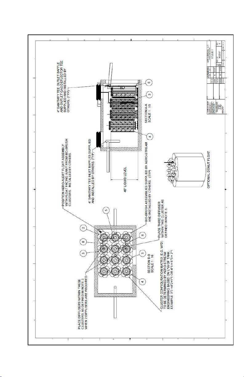
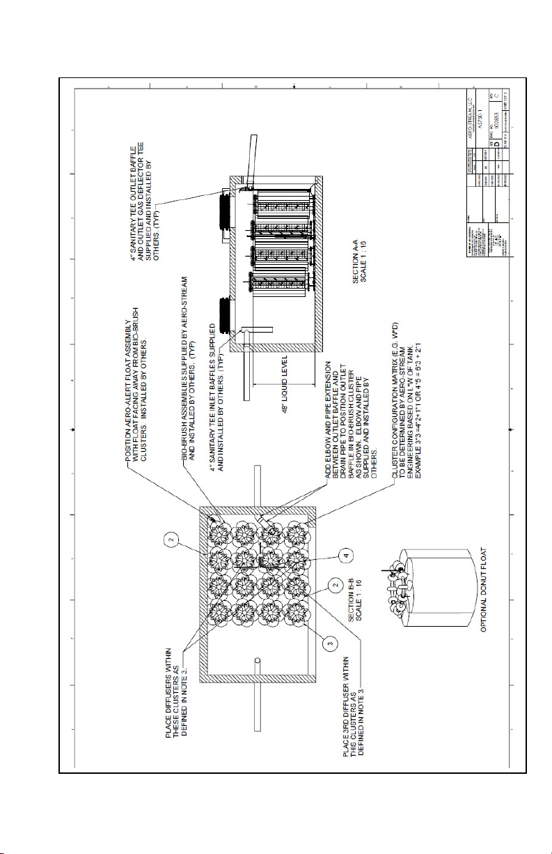
Figure 10, AS500-1 Cluster Arrangement
Other manuals for AS500-1
1
This manual suits for next models
4
Table of contents


