Aerobics Silver Select XP User manual
PaceMaster
SilverSelectXP
OWNER’SMANUAL
Manufactured by: Aerobics Inc., 34 Fairfield Place West Caldwell, NJ 07006, (973) 276-9700
www.pacemaster.com
Part # TMP1627 Rev. 09/01/09

2
TABLE OF CONTENTS
INTRODUCTION 3
IMPORTANT SAFETY INSTRUCTIONS 4
ASSEMBLY INSTRUCTIONS 5-15
Unpacking Your Treadmill 5
Installation Requirements 6
Tools Required for Assembly 6
Grounding Instructions 6
Assembly 7-14
Testing Your Treadmill 15
THE PACEMASTER SILVER SELECT XP CONTROL PANEL 16-18
OPERATING INSTRUCTIONS 19-28
MetricUnits 19
Setting Your Weight and Age 19
Warm Up and Cool Down 19
QuickStart 20
Timed Workout (Manual) 21
Programs 22-27
P1 22
P2, P3, P4, P5, and P7 23
P6 24
P8 and P9 24-26
Program Specifications 27-28
HEART RATE 29-31
Monitoring your Heart Rate 29
Heart Rate Programs (H1, H2, and H3) 30-31
EXCLUSIVE PACEMASTER FEATURES 32-33
ExercisePreview 32
AerobicPoints 32
Personal Electronic Trainer 32-33
CARE AND MAINTENANCE 34
Deck and Tread Belt Cleaning 34
Lubrication 34
Centering the Tread Belt 34
Cup Holder 35
TROUBLESHOOTING 36-39
Electronic Error Codes 36-37
Noises 38
Hesitation of the Belt 38-39
Drive Belt Tension Adjustment 38-39
Tread Belt Tension Adjustment 39
FREQUENTLY ASKED QUESTIONS 40
PACEMASTER TECHNICAL SPECIFICATIONS 41

3
INTRODUCTION
Congratulations and thank you for choosing PaceMaster – your partner in achieving your fitness goals and mastering your well-being.
PaceMaster’s advanced digital technology allows your treadmill to process information instantly, anticipating and adjusting to meet your
needs. Think of it as your own personal trainer.
PaceMaster’s superior components and US manufacture ensure we produce treadmills of the highest quality while also offering excellent
value for your dollar. PaceMaster treadmills have consistently received praise from a wide range of nationally recognized publications.
To get the most from your PaceMaster, please read this owner’s manual carefully before starting to use the treadmill. The manual contains
important information about the assembly, operation and maintenance of the machine.
Please ensure you read and fully understand all safety information. DANGER, CAUTION, or WARNING indicates
important safety warnings throughout the manual. Failure to read and understand these warnings may result in personal injury or damage
to your treadmill.
Tip: indicates a useful suggestion when installing, maintaining or using your treadmill.
Your PaceMaster treadmill is capable of varying your workout by changing speed, incline and time. It can also measure the effect of your
workout in a number of different ways. For example “Aerobic Points” (see page 32) is a well tested method to set workout goals based on a
desired level of overall fitness. Your PaceMaster treadmill can automatically calculate Aerobic Points for you. In this way your treadmill acts
like your own personal trainer.
Please take the time to familiarize yourself with the range of functions available. This will help you work with your PaceMaster treadmill for
maximum efficiency to achieve your fitness goals and master your well-being.
We wish you an enjoyable and rewarding partnership with your PaceMaster treadmill.
This treadmill is in compliance with EN 957-2 class H.
The PaceMaster Silver Select XP treadmill is designed for home use only.
217

4
IMPORTANT SAFETY INSTRUCTIONS
Read these instructions before using your treadmill
CAUTION: Before starting any exercise program, contact your personal physician and have a complete physical. This is highly
recommended if you have not been on a regular exercise program within the last year, or are over 35 years of age, or are overweight.
CAUTION: If at any time during your exercise program you find the exercise abnormally difficult or you encounter dizziness, feel
faint, experience chest pains, feel as if your heart may be skipping beats, you experience forced heavy breathing after minimal exercise or
severe pain in your legs, ankles, knees, etc. STOP EXERCISING and consult your physician.
WARNING: To reduce the risk of burns, fire, electrical shock or injury:
•Never operate your PaceMaster treadmill without clipping the magnetic safety key to your clothing at waist level.
•Your PaceMaster treadmill is not designed for use by children under the age of 18 without strict parental supervision.
•Close supervision is necessary when the treadmill is used by or near children, disabled persons or pets.
•Use your PaceMaster treadmill only for its intended use as described in this manual. Do not use accessories or attachments not
recommended by Aerobics, Inc.
•Never operate your PaceMaster treadmill if it has a damaged cord or plug, if it is not operating properly, if it has been dropped or
damaged or if it has been immersed in water. Should any of these occur, contact your authorized PaceMaster retailer or service
center for examination or repair.
•Keep the cord away from heated surfaces.
•Never drop or insert any object into any opening on the treadmill.
•Do not use outdoors.
•Always unplug your PaceMaster treadmill during an electrical storm or during extended periods of non-use.
•Do not operate where aerosol (spray) products are being used or where oxygen is being administered.
•Position the treadmill with a minimum of 4 feet (1219mm) of clearance between the rear of the treadmill and any wall or obstruction.
•Do not allow anyone to reach under or be too near your PaceMaster while it is in use.
•Do not attempt to mount or dismount the tread belt while it is running.
•Never allow more than one person on your PaceMaster treadmill at any time.
•Never move the treadmill while it is plugged into the electrical outlet.
•When you are finished exercising, leave your PaceMaster treadmill in a non-elevated position to avoid toys and other objects from
becoming trapped beneath.
•Wear appropriate running or walking shoes and attire while exercising.
•The treadmill should be turned off after each use by removing the safety magnetic key.

5
ASSEMBLY INSTRUCTIONS
Unpacking Your Treadmill
Confirm that all of the items pictured below were packed in the box
Before assembling your treadmill, open the hardware package and verify that the contents of the package match the hardware legend
included in the hardware package. If any parts are missing, contact the authorized PaceMaster retailer where you purchased your
PaceMaster treadmill.
Hardware Kit
Owners
Manual
Control Panel Front
Control Panel Back
Motor Cover
Handle Bar
Cup Holder w/ Foam Pad (2 pcs)
Panel Support Tube (2 pcs)
Treadmill Base
Side Rail (2 pcs)
Chest strap
Upright Assembly

6
ASSEMBLY INSTRUCTIONS (cont’d)
Installation Requirements
Your PaceMaster should be installed indoors on a flat, level surface near a 120Volt/ 15Amp outlet. PaceMaster requires a dedicated, non-
switched outlet that is not part of a GFI (Ground Fault Interrupter) circuit, preferably no more than 5 feet from the outlet to eliminate the
need for an extension cord. You must have a minimum of 4 feet of clearance between the rear of the treadmill and any wall or obstruction.
TIP: If you are installing your PaceMaster on a carpeted surface, use a treadmill mat or a scrap piece of carpet underneath the treadmill to
avoid soiling of the carpet. Deep pile carpet is not recommended.
Tools Required for Assembly
•3/16" Allen wrench (supplied)
•7/16” combination wrench (2X)
•Phillips head screwdriver
•Slotted Head Screwdriver
Grounding Instructions
DANGER: This product must be properly grounded. If it should malfunction or
become inoperable, grounding provides a path of least resistance for electric current to
reduce the risk of electric shock. This product is equipped with a cord having an
equipment-grounding conductor and a grounding plug. The plug must be plugged into
an appropriate outlet that is properly installed and grounded in accordance with all local
codes and ordinances. See example to the right.
WARNING: Improper connection of the equipment grounding-conductor can result in a risk of electrical shock. Check with a
qualified electrician or serviceman if you are in doubt as to whether the product is properly grounded. Do not modify the plug provided with
the product. If it will not fit the outlet, have a proper outlet installed by a qualified electrician. This product is rated for more than 15
amperes and is for use on a circuit having a nominal rating of 120 volts. It is factory equipped with a specific electric cord and plug to
permit connection to a proper electric circuit. Make sure that the product is connected to an outlet having the same configuration as the
plug. No adapter should be used with this product. Attempting to bypass it with an adapter or in any way defeating its purpose can
result in a serious shock hazard.
As a safety precaution, unplug the treadmill during electrical storms or if the treadmill will not be in use for periods greater than one week.
CAUTION: If you need to use an extension cord it must be a 14 gauge, three wire cord, no longer than 12 feet.

7
1
2
ASSEMBLY INSTRUCTIONS (cont’d)
Step One:
Carefully place the bottom of the upright (1) on the
frame (2) so the two holes in the plate at the bottom
of the upright line up with the holes in the frame.
Insert the 3.5” carriage bolts (3) through the upright
and the frame.
Loosely install a 1/4-20 kep nut (4) to each carriage
bolt to keep the upright in place. Follow the same
procedure for the other side of the upright. Do not
tighten any nuts until Step Ten.
1
4
2
4
32

8
Purse Lock Clip
Shown Closed
18
9
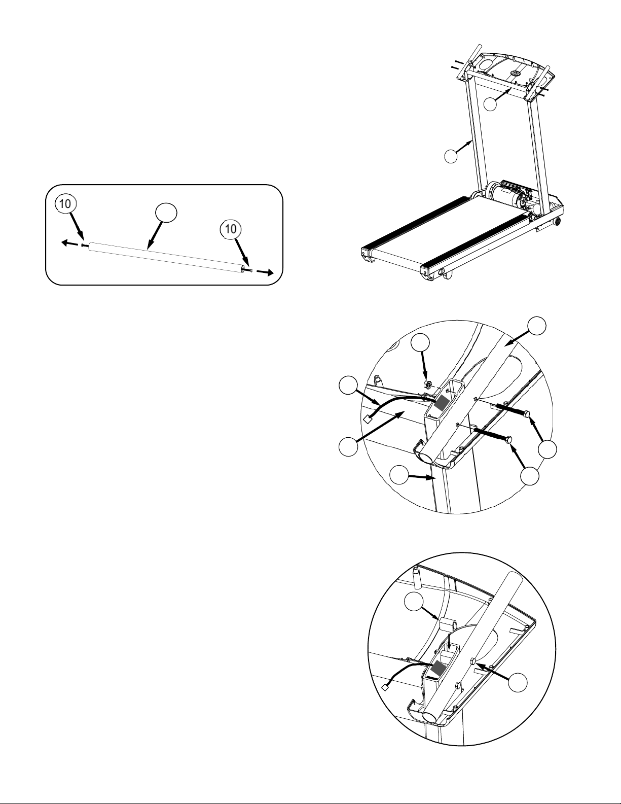
ASSEMBLY INSTRUCTIONS (cont’d)
CAUTION: Make sure the treadmill is NOT plugged into the electrical outlet until assembly is
competed.
StepTwo:
With the upright loosely bolted in place, plug the black wire harness (5) into the socket (6) on the power
supply board. Twist open the purse clip at (7a) insert the wire harness (5) and secure the purse clip.
Confirm the wire harness is positioned as shown at point 5 above. Follow the same procedure for purse
clip (7b).
Step Three:
Route the wire harness (8) through the opening in the
back of the control panel (9), then lower it on to the
upright and let it rest as shown in the drawing.
7b 7a 5 6
9
15
10
13
14
8
12
ASSEMBLY INSTRUCTIONS (cont’d)
Step Four:
A. Remove the 3.5” Hex bolts (10) from both ends of handle bar (11). See FIG.
A1. Place the Handle Bar (11) between the uprights (2) as shown in FIG. A2.
B. Using the 3.5” Hex bolt (10), loosely screw together the
panel support tube (12), the upright (2), and the handle
bar(11). See FIG. B. Follow the same procedure on the opposite side.
Using the 3” hex bolt (13) and a ¼-20 kep nut (14) loosely screw together
the panel support tube (12) and the upright(2). See FIG. B. Follow the
same procedure on the opposite side.
Make sure wire harness (8) is routed between bolts (10) and (13). See
FIG. B.
C. Place spacer (15) in the upright on top of bolt (13) on both sides. See FIG C.
Proceed to securely tighten all 4 bolts.
NOTE: If spacer (15) is dropped into the upright (2) then upright must be
removed in order to retrieve the spacer. If spacer is not retrieved it will make
noise when machine is in use.
2
11
11
Fi
g
. A1
Fi
g
. A2
Fig. C
11
Fig. B
15
13
2

10
Connector
ASSEMBLY INSTRUCTIONS (cont’d)
Step Five:
Lower the top of the control panel (16) on to the
upright assembly as shown below
Step Six:
Route the wire harness (8) as shown below. Pull the wire harness taut then apply tape #1 exactly as shown. Repeat and apply tape #2
exactly as shown. Harness must be flat against the side wall of the black plastic housing between tape#1 and tape #2. Plug the end of the
wire harness into the connector on the circuit board. All the slack in the wire harness should be near the connector.
NOTE: Wireless heart rate will not work if these instructions are not followed.
16
11
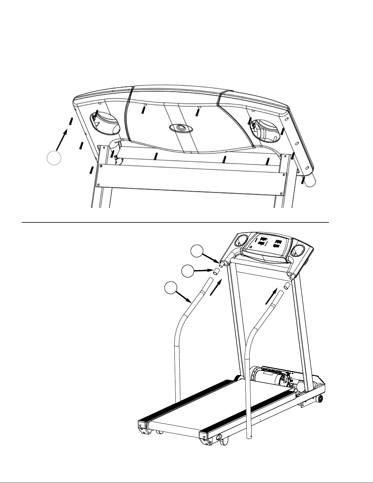
ASSEMBLY INSTRUCTIONS (cont’d)
Step Seven:
Screw together the two halves of the control panel using the 14 one inch pan head screws (17). Start with the screw labeled 17 and
proceed in a clockwise tightening sequence.
17
Step Eight:
Insert side rail spacer (18) onto the black
panel support tube (12). Slide side rail (19)
over the spacer. Repeat procedure on
opposite side of the machine.
Note: Make sure the siderail (19) slides all
the way into the panel.
19
18
12
17

12
ASSEMBLY INSTRUCTIONS (cont’d)
Step Nine:
Insert one of the 4” slotted head bolts (20)
through the side rail (19), the side rail bracket
(21) (the foam on the bracket should be at the
top, facing the frame) and finally through the
frame (2). Install a 1” fender washer (22) and
a ¼-20 kep nut (4) to the bolt and hand
tighten. Install the other side rail following the
same procedure. Tighten both side rails with
a 7/16” wrench.
Step Ten:
Tighten the 4 ¼-20 kep nuts (4) installed
in step one.
These will secure the upright assembly
422
20
21
19
4

13
24
25
ASSEMBLY INSTRUCTIONS (cont’d)
Step Eleven:
Insert the cup holder (23) into the hole in the control panel (16). Push down until you hear and
feel it firmly snap in place.
Note: The cup holder should sit flush to the control panel when it is snapped in place. If not, remove
cup holder and rotate 180 degrees, then reinstall.
IMPORTANT:
Cup holder comes with a black foam pad to be
kept on the bottom of the cup holder. This will
help protect your cup holder from being scratched
and reduce noise.
DO NOT THROW AWAY.
Step Twelve:
To install the motor cover, stand in front of the treadmill. Pick up the motor cover (24) so
it is level. Holding the motor cover level and waist high, tilt it 45 degrees by lowering
your left hand. Then slide it between the handlebars and lower the motor cover until it is
level. Lower the cover all the way, keeping it level. Screw the two #8x1/2” black sheet
metal screws (25) into the front of the motor cover. Press down on each side of the
motor cover where it meets the silver plastic deck shrouds to lock the Velcro pads into
place.
CAUTION: Do not raise or lower motor cover without it being level.
14
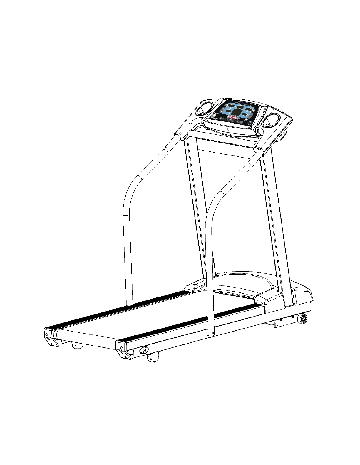
ASSEMBLY INSTRUCTIONS (cont’d)
Step Thirteen:
Assembly is complete, please proceed to testing your treadmill on the next page.

15
Testing Your Treadmill
Your PaceMaster has been adjusted and tested at the factory. However, due to changes that can occur during shipment, it should be
tested prior to use. Once you have assembled your treadmill and it is located where it will be used, proceed as follows. (Do not make any
adjustments unless necessary.) For the purpose of this test, DO NOT stand on the tread belt. Once tested, always start and finish
on the tread belt.
Follow the steps below to confirm proper operation of your treadmill after assembly.
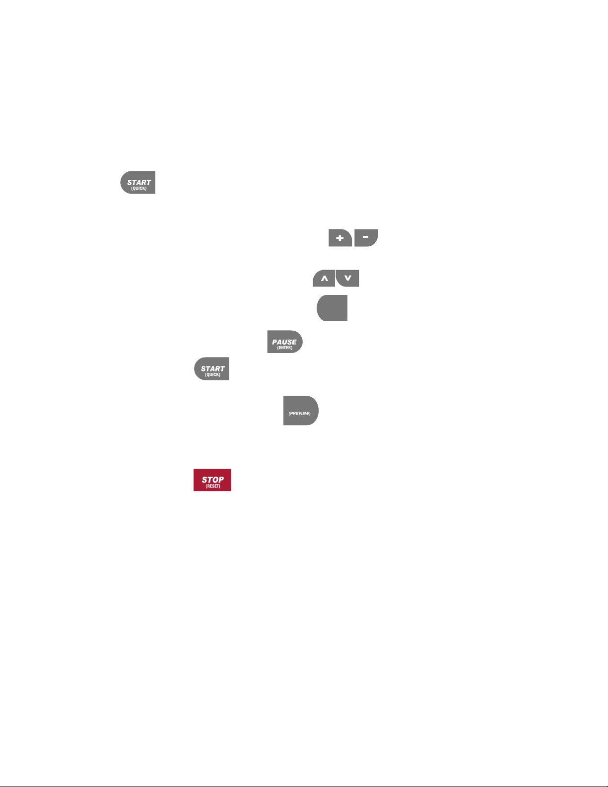
Step One:
After your treadmill is in place and plugged in to the wall outlet, insert the magnetic safety key into the recess on the control panel.
Step Two:
Press the Incline buttons to set your weight and the Speed buttons to set your age, then press the
button.
Step Three:
Set the workout speed by pressing the SPEED button until the SPEED display shows 2.5 mph.
Step Four:
Press the START button. Within a few seconds, the tread belt will begin to move. The speed display will flash until the tread
belt has reached the set speed.
Step Five:
After the treadmill has reached 2.5 mph, observe the tread belt to make sure it is reasonably centered. If the tread belt is not reasonably
centered, press the STOP button and refer to “Centering the Tread Belt” in the Care and Maintenance section of this manual.
Once the tread belt is reasonably centered, run the treadmill at 2.5 mph for 5 minutes to be sure it remains centered.
Step Six:
To test the elevation, the tread belt must be moving. Press the incline up button to raise the elevation to 5% incline. The elevation
will be displayed in the INCLINE display window. Once it reaches 5%, press the incline down button to reduce the incline to 0%. If
the treadmill does not elevate, or displays “Err” in the incline display consult the troubleshooting section of this manual.
Step Seven:
Press STOP You are now ready to use your treadmill.
16
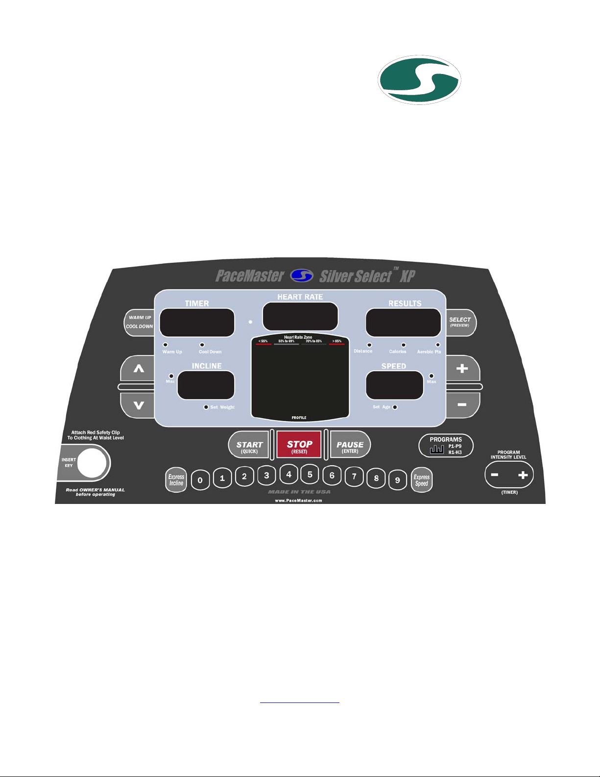
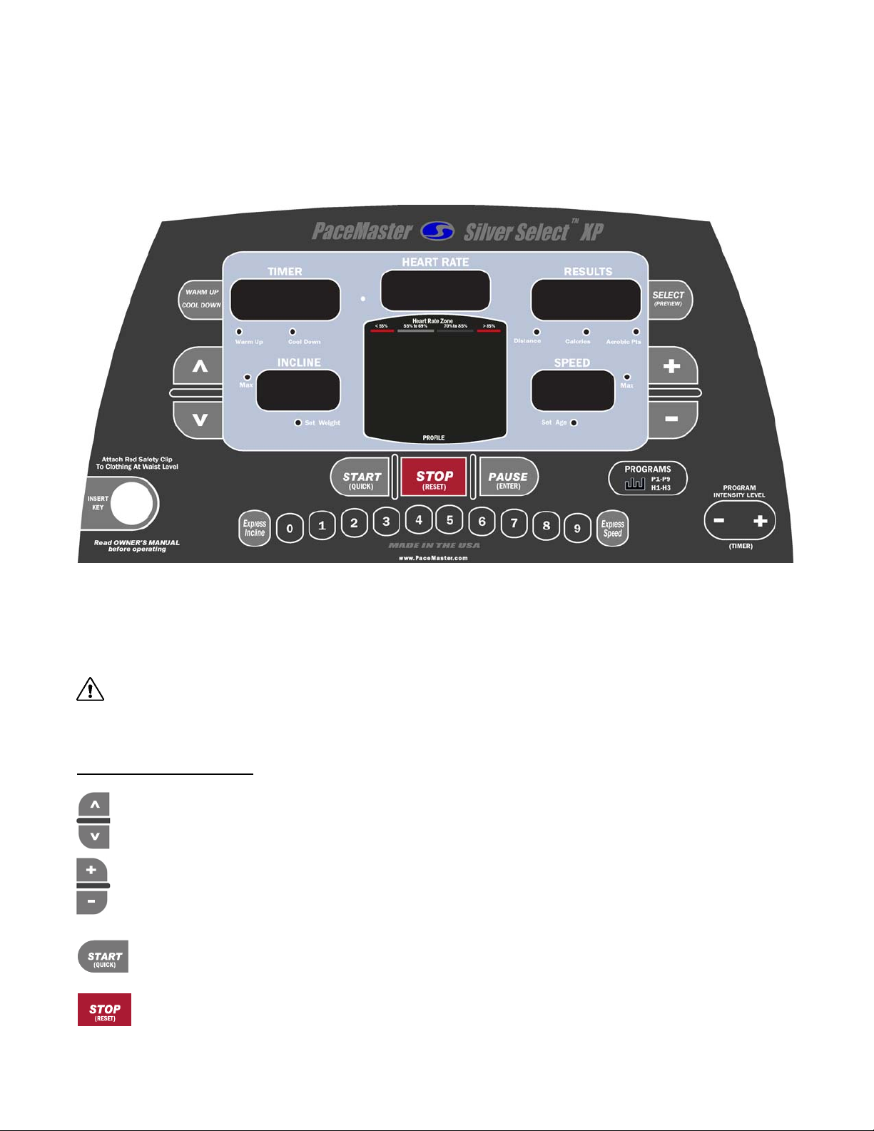
THE PACEMASTER SILVER SELECT XP CONTROL PANEL
Although your PaceMaster has many advanced features to provide versatility in meeting exercise needs, basic operation is extremely
easy. Basic operation involves setting your TIME and SPEED goals, then pressing the START button. Your PaceMaster will gradually
accelerate to the set speed, maintain that speed until the timer counts to zero and then gradually come to a complete stop. During your
exercise, your time remaining, current speed, distance traveled, calories burned and Aerobic Points earned are displayed.
MAGNETIC SAFETY KEY - The MAGNETIC SAFETY KEY, with its red cord and garment clip, is an important safety feature. It is also the
ON/OFF switch. To power up your treadmill, first attach the garment clip to your clothing at waist level then insert the magnetic key into
the round recess on the control panel. This safety key provides a means of powering down the treadmill in an emergency situation. This
treadmill will not operate unless the MAGNETIC SAFETY KEY is engaged. During exercise, an emergency stop can be made at any time
by pulling on the cord to release the key from its slot.
CAUTION: Using the key to stop the treadmill is an emergency procedure only! To end your exercise routine normally, press
the STOP button or allow the timer to count down to zero. Once the belt has come to a complete stop, remove the MAGNETIC SAFETY
KEY to turn off the treadmill. When not in use, store the MAGNETIC SAFETY KEY in a safe place to prevent unauthorized use.
BUTTON DEFINITIONS
INCLINE ▲and ▼buttons – Have two functions. 1) Use these buttons to adjust the user weight. 2) These buttons increase or
decrease incline to simulate exercising up hill. Incline can be changed at any time during your workout. At the end of your
workout, the Incline setting will automatically return to 0%.
SPEED + and −buttons – Have two functions. 1) Use these buttons to adjust the user age. 2) Use these buttons to increase or
decrease Speed. Adjust your speed at any time during your main workout. The treadmill computer controls the speed during the
warm up and cool down phases of your workout.
START (QUICK) button – Press this button to start your workout or to return from a paused state.
STOP (RESET) button – Press this button to end your workout. If pressed when the treadmill is stopped it will reset the
display.
silr uSA
17
WARM UP
COOL DOWN
SELECT
P1-P9
H1-H3
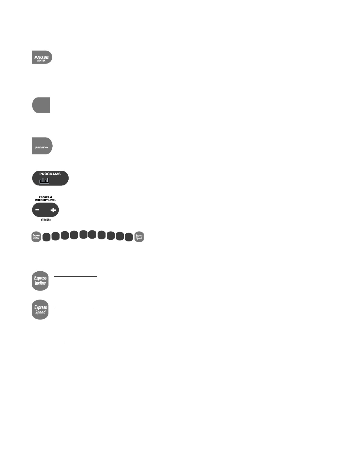
THE PACEMASTER SILVER SELECT XP CONTROL PANEL (cont’d)
PAUSE (ENTER) button – Has two functions. 1) It is used to ENTER your body weight and the program time for a workout.
2) During a workout, pressing this button will PAUSE your exercise, or put it "on hold". The treadmill stops but retains the
distance, calories and Aerobic Points accumulated thus far, as well as the speed setting and remaining time. The symbol -P-
flashes in the SPEED display to indicate the PAUSE feature has been activated. To resume your workout where you left off, press
START. This feature is will not work during a cool down. This feature can not be used in the cool down mode or heart rate control
programs.
Warm Up / Cool Down button – Prior to starting, this button allows you to add or remove a 5-minute Warm Up and/or 5-
minute Cool Down phases to your workout. During Warm Up, pressing the Warm Up / Cool Down button discards the
remaining warm up time and advances you to the main workout phase. During the main workout, pressing the Warm Up / Cool
Down button discards the remaining time and starts the Cool Down phase. Fitness experts strongly recommend a warm up before and a
cool down following your aerobic workouts. See the WARM UP and COOL DOWN section in this manual for details.
SELECT (PREVIEW) button – Has two functions. 1) Prior to and during your workout this button is used to select the value
(distance, calories, or aerobic points) displayed in the Results window. During your workout you can press and hold this
button until the word “SCAn” appears in the Results display, now each value (distance, calories, and points) will be displayed
for 3 seconds on a rotating cycle. 2) It is used to change the treadmill setting from English units to Metric units (see “Metric units” page 12).
PROGRAMS buttons – The PROGRAMS button is used to select one of the programmed workouts. For details, refer
to the PROGRAMS section in this manual.
PROGRAM INTENSITY LEVEL (TIMER) buttons – Has two functions. 1) Use these buttons to set your workout time for
both a TIMED WORKOUT and the factory WORKOUTS. 2) Use these buttons to set or change the program intensity level
in a programmed WORKOUT.
01234 5 6789EXPRESS KEYS – As an alternative to continually pressing the INCLINE ▲or
▼buttons to increase or decrease incline or the SPEED + or - buttons to increase or decrease speed, See the section “Using Express
Buttons”.
EXPRESS INCLINE –. For example, if you want to adjust the incline to 10%, press the EXPRESS INCLINE button, then 1, then
0. The incline will automatically increase to 10%. The EXPRESS INCLINE buttons adjusts incline in 1.0% increments. To
adjust the incline to 8.0%, press EXPRESS INCLINE, then 8.
EXPRESS SPEED – For example, if you choose to increase the speed to 5.0 mph, press the EXPRESS SPEED button, then 5,
then 0. The speed will automatically be increased to 5 mph. The EXPRESS SPEED buttons adjust speed in 0.1 mph
increments. To adjust speed to 5.3 mph, press EXPRESS SPEED, then 5, then 3.
DISPLAYS
RESULTS display – Displays Distance, Calories and Aerobic Points. Additionally, during the selection or use of a programmed
WORKOUT the chosen or current intensity level is displayed.
TIMER display – Displays time in minutes and seconds (mm:ss) up to 59 minutes and 59 seconds. Times of 1 hour to a maximum of 4
hours are displayed as hours and minutes (– h: mm), with the dash as the first digit. For example, – 1:15 represents one hour and 15
minutes. In Quick Start, the TIME display counts up (elapsed time). In other modes of operation the TIME display counts down (time
remaining). When using warm up and/or cool down, time will display as a 5-minute countdown for the warm up phase, a countdown for the
main exercise phase and then a 5-minute countdown for the cool down phase.

18
THE PACEMASTER SILVER SELECT XP CONTROL PANEL (cont’d)
SPEED display –Displays Speed from 0.5 mph to 11.0 mph, in 0.1 mph increments. Prior to starting, the displayed value is the Speed the
treadmill will seek once START is pressed. Once your workout has begun, the current Speed is displayed. The speed display will flash
until the set speed is reached.
INCLINE display – Displays Incline from 0% to 15.0%, in 0.5% increments. Prior to starting, the displayed value is the current incline or
the incline the treadmill will seek once START is pressed. Once your workout has begun, the current Incline is displayed.
HEART RATE display – Displays actual heart rate if you are wearing your Polar wireless chest strap. Refer to the Heart Rate section in
this manual for more information.
INDICATOR LIGHTS
Set Weight indicator – 3 seconds after the magnetic safety key is inserted, the Set Weight indicator flashes and the last entered body
weight is shown on the INCLINE display. Body weight can be adjusted using the INCLINE buttons. Once the desired setting is displayed,
press PAUSE (ENTER).
Set Age indicator – 3 seconds after the magnetic safety key is inserted, the Set Age indicator flashes and the last entered age is shown
on the SPEED display. Age can be adjusted using the SPEED buttons. Once the desired setting is displayed, press PAUSE (ENTER).
INCLINE Max indicator – When illuminated during the selection of a programmed workout, the displayed Incline is the maximum incline
that will be encountered during the selected workout and intensity level.
SPEED Max indicator – When illuminated during selection of a programmed workouts, the displayed speed is the maximum speed that
will be encountered during the selected workout and intensity level.
WARM Up and COOL DOWN indicators – Illuminated Warm Up or Cool Down indicators show that these routines will be part of the
workout. When in the Warm Up or Cool Down mode, the appropriate indicator will blink.
DISTANCE, CALORIES, And AEROBIC POINTS indicators – They tell you which value is being displayed in the Results window.

19
OPERATING INSTRUCTIONS
Initially, you may want to keep both hands on the side rails until you feel comfortable walking on your PaceMaster. Once you feel
comfortable, try removing your hands to let them swing naturally, as you would when walking outdoors. Always hold on to the side rail or
front handle bar with one hand when operating the buttons of the control panel.
THE FIRST STEP
Stand on the center of the treadmill belt. Attach the garment clip on the end of the magnetic safety key to your clothing at waist level.
Insert the safety key into the recess on the control panel keyboard.
METRIC UNITS
PaceMaster treadmills can be configured to operate in English (lbs, mph, and miles) or Metric units (kg, kph, and kilometers) of measure.
To determine the present configuration of your PaceMaster insert the magnetic key, if “USA” is displayed in the “RESULTS” window it is
configured in English, if “Eur” is displayed in the “RESULTS” window, it is configured in Metric. To change between English and Metric
insert the magnetic key, as soon as the current setting (USA or EUR) is displayed in the Results window, press and hold the SELECT
(PREVIEW) button until the setting changes. Press PAUSE (ENTER) to confirm the selection.
SETTING YOUR WEIGHT AND AGE
Your PaceMaster calculates caloric expenditure based on the formula developed by the American College of Sports Medicine. To ensure
accuracy, your weight is required. Your PaceMaster calculates heart rate information based on the age you enter prior to your workout.
To ensure safety and accuracy, your age is required. Once the magnetic key has been inserted, Press the Incline buttons to
set your weight and the Speed buttons to set your age, then press the button.
WARM UP AND COOL DOWN
By warming up prior to beginning the aerobic phase of your workout, you accomplish 2 goals; you stretch and warm up the muscles of the
back and extremities and create a slight acceleration of the heart rate so that the body can move gradually into the higher heart rate of the
aerobic phase. The aerobic phase should be followed by a minimum 5-minute cool down in which you keep moving at a slower pace. This
allows your heart rate to gradually decline and your body to gently adjust to the end of a workout instead of abruptly stopping. The cool
down phase also allows blood to be pumped from the lower extremities back to the central circulatory system. Simply put, the function of
warming up and cooling down is to ease you from a resting state into an active state and back to a resting state.
The treadmill’s computer, based on your main exercise starting and finishing speeds respectively, automatically calculates warm up and
cool down speeds.
When in the warm up mode, the TIME display window counts down from 5 minutes and the Warm Up indicator light will blink. When in the
Cool Down mode, the TIME display window counts down from 5 minutes and the Cool Down indicator light will blink.
To add warm up and/or cool down to a TIMED workout press the Warm Up / Cool Down button. The indicator light will blink, indicating that
the desired mode has been added to your workout. You will also notice that the workout time increases by 5 minutes for each addition.
To shorten the warm up mode, press the Warm Up / Cool Down button once. Warm up will be ended and you will advance into the main
exercise. To shorten the main exercise, press the Warm Up / Cool Down button and you will automatically begin the cool down phase. To
end the cool down, press STOP and your session will come to a close.
A cool down phase can be added to any workout (even if it wasn’t chosen prior to beginning the workout) by pressing the Warm Up / Cool
Down button.
Now you are ready to choose your workout mode. Whether it is Quick Start, Timed Workout (Manual), or one of the Variable Intensity
Programs, the following pages give you step-by-step instructions on how to use each workout.
20
QUICK START
Quick Start allows you to begin your workout by pressing one button. You control the speed, incline and time.
Step One:
Stand on the running belt and attach the garment clip on the end of the magnetic safety key to your clothing. Insert the safety key into its
recess on the control panel.
Step Two:
Press the START button. Within a few seconds, the tread belt will begin to move. The speed display will flash until the tread
belt has reached the set speed.
•Adjust the speed at any time during your workout by pressing the SPEED buttons. Speed will adjust in 0.1 mph
increments
•Add incline at any time during your workout by pressing the INCLINE buttons. Elevation will adjust in 0.5% increments.
•Add a 5 minute Cool Down to the end of your workout by pressing the
WARM UP
COOL DOWN
button when you are ready.
TIP: You can pause your workout by pressing the PAUSE button. This feature is not available in cool down or heart rate
control. To resume, press the START button.
TIP: During your workout you can press and hold the SELECT
SELECT
button until the word “SCAn” appears, each value (distance,
calories, and points) will now be displayed for 3 seconds on a rotating cycle.
Step Three:
To end your workout, press the STOP button. The treadmill will display the total time distance, calories, and Aerobic Points.
If a problem should occur, your PaceMaster can be stopped quickly by pulling on the magnetic safety cord to dislodge the key from the
control panel. The treadmill will stop a bit more abruptly, but still gently enough to prevent you from being injured. This is an emergency
procedure only and should not be used as the normal stopping procedure.
Table of contents
Popular Fitness Electronic manuals by other brands


Fitbit Zip
Fitbit Zip Force product manual

Kettler
Kettler ST 7609-68 Training and operating instructions

Polar Electro
Polar Electro CS600X Getting started guide

Kettler
Kettler HOI FRAME instructions

Schwinn
Schwinn MPower Echelon2G Technical Procedure

Octane Fitness
Octane Fitness XT Setup & operation manual