AEROCOMPACT S5 User manual

Install. AE S 2.1 US V0.0 2017-01
INSTALLATION MANUAL
AEROCOMPACT S
5°/10°/15°
2

3
INTRODUCTION
Thank you for choosing the Aerocompact mounting system.
Please read these instructions carefully before starting the installation and make sure that you
can meet the required guidelines in this installation manual.
An important part of this installation manual is the additional
designed project report with the structural analysis based on
the project location. Please make sure that the position of the
modules on the roof and the ballast distribution is installed as
required in project report. In case the module layout changes
do to circumstances like obstructions, the ballast calculation
needs to be modified with the Aerotool software. It is required
to design the static calculation of the system with the Aero Tool
Software program (Solar.Pro.Tool).
The technical documentation is part of the product. The com-
pany AEROCOMPACT is not liable for damages occurring from
non-compliance with the installation instructions, particularly the
safety instructions, as well as from misuse of the products. In
addition to this installation manual the current general condi-
tions as well as warranty conditions apply. The current versions
are available at www.aerocompact.com
Faults and damage as well as limited or lacking operability of the
system as a result of assembly that is faulty and/or deviating
from the installation instructions and/or the project report
(Solar.Pro.Tool) preclude a material defect is not the responsibil-
ity of Aerocompact. With unprofessional installation, all rights of
the purchaser shall expire. The required compressive strength of
the roof insulation and the maximum static roof load needs to be
checked before starting the installation.
Photovoltaic flat roof systems are not maintenance free. Main-
tenance, particular the right position of the ballast blocks and
the building protection pads should be conducted annually. For
exceptional high-wind events, we recommend to do a Mainte-
nance and system check right after the storm event.
Faults and damage as well as limited or lacking operability of the
system as a result of assembly that is faulty and/or deviating
from the installation instructions and/or the project report (So-
lar.Pro.Tool) preclude a material defect is not the responsibility
of Aerocompact. With unprofessional installation, all rights of the
purchaser shall expire.
The system warranty shall be effective only if all system compo-
nents were purchased from Aerocompact.
In case of doubt, please contact the Team of Aerocompact
or call 0800 578 0474
This racking system may be used to ground and/or mount a PV
module complying with UL 1703 only when specific module has
been evaluated for grounding and/or mounting in compliance
with the included instructions. In order to meet this requirement,
installers are supposed ro first seek approval, e.g. through gen-
eral installation instructions or specific application documents,
from module manufacturers, in particular for attaching the mod-
ule clamps along the shorter side of the module frame, and for
grounding/bonding the module frame by clamp-integrated pins.
Aerocompact offers assistance to achieve such approval.
A list of PV modules with proven compliance in terms of UL 1703
is being built up by and can be obtained from Aerocompact upon
request.
The material of the building protection mat that is included in the
scope of delivery avoids accelerated ageing (e.g. through leaking
of plasticizers) of roof membranes, and it usually provides suffi-
cient friction between racking and roofing. Due to the variety of
different sealing types previously and currently customary on the
market, materials compatibility as well the friction coefficient for
ballast calculations must be checked / verified by the assembly
company / buyer for any individual installation. If the measured
friction coefficient (lowest value out of several tests under dry
and wet conditions) is below the value assumed for ballast calcu-
lations (default is 0.7), the system design must be recalculated
and modified accordingly in order to ensure system stability.
If the Roof-Gravel is located right on the water-bearing roof the
Aerocompact System can not be installed on the gravel layer.
The gravel must be removed in this case in the area of the Alumi-
num Brackets.

4
smart mounting solutions
YOUR BIG ADVANTAGE
>25 years product warranty
>Wind tunnel tested
>new protection pads for long service life and enhanced friction
>TUV certified, conforms to UL 2703
>Patent pending
>ballast-only as a standard, roof penetrations optional
>Optimum module ventilation
>Complimentary ballast calculation incl. roof layout
>Made in Europe
>Minimum Order only 2 KWp
>Module Clamps with grounding pins
>TUV certified, conforms to IEC 61215
>Class A fire rated acc. to ANSI/UL 1703 when equipped with
side deflectors (tested with the S5 racking type, to be con-
firmed for S10, S15, and + systems).
>Best price value available
>The fastest installation in the industry 1 kWp 5 min., 2 men
>Statically optimized system
>Less material = Less shipping costs
>Optimized wind suction, therefore less ballasting
than other systems
>Optimum water drainage
>Suitable for roof edge zones

5
New System Update 2.1
NEW module-clamp
incl. grounding-pins, TUV certified to UL2703
NEW cable management solution
NEW fleece building protection mat
certified and long-term tested

6
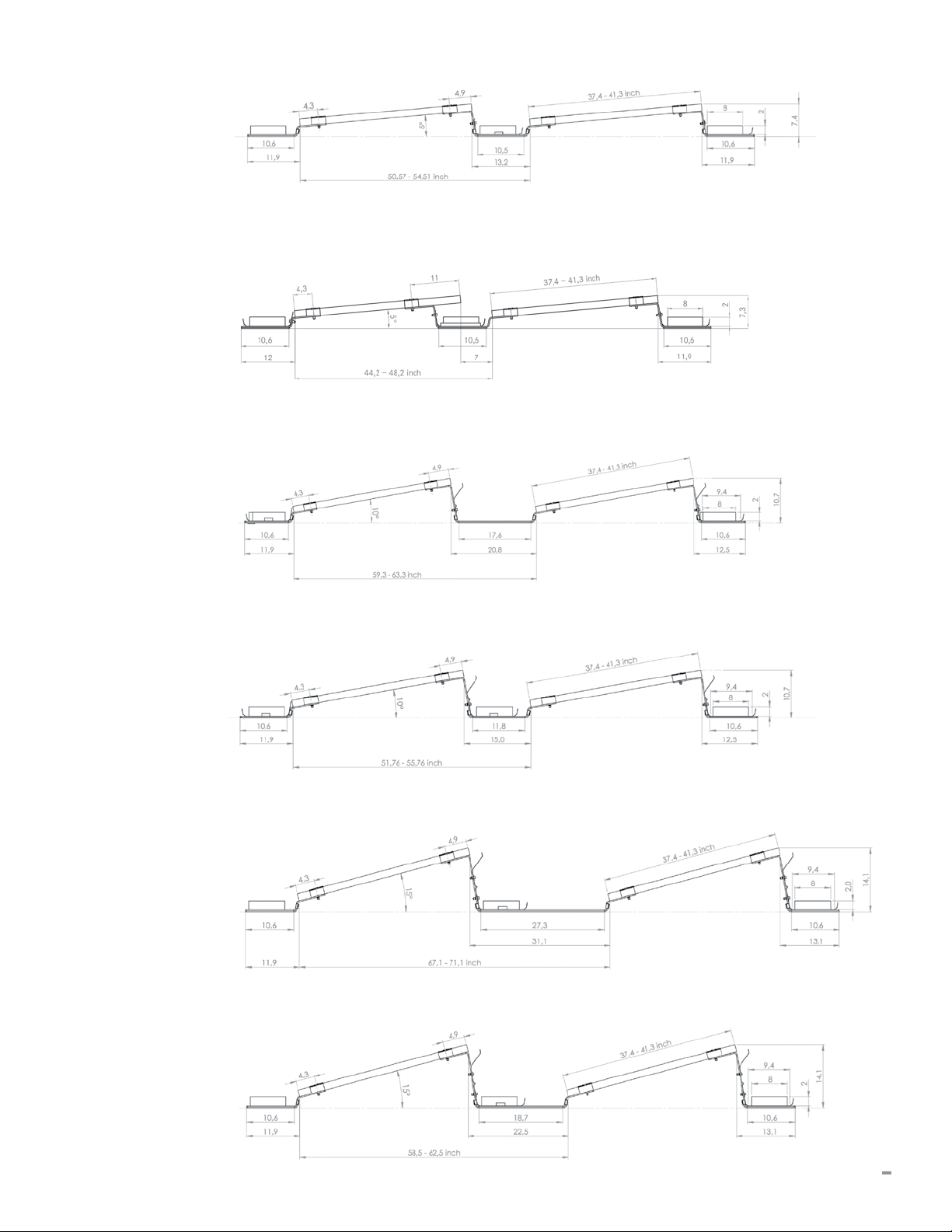
Technical Details
Mounting Tilt: AEROCOMPACT S: 5°, 10°, 15°
Inter-Row Spacing: AEROCOMPACT S 5 (25°): 13.2 inch (335 mm)
AEROCOMPACT S 5 (30°): 7 inch (178 mm)
AEROCOMPACT S 10 (25°): 15 inch (380 mm)
AEROCOMPACT S 15 (25°): 22.5 inch (571 mm)
Min. Array Size: AEROCOMPACT S: 2 rows with 3 modules / 3 rows with 2 modules
Roof Edge Zone: Roof areas F and G can be used
Module Dimensions: 37.4–41.3 inch x 61.1–81.9 inch (width – length)
(standard; other dimensions upon request)
Max. Roof Slope: 5 Degree (standard; steeper roofs upon request)
Roof Height: up to 60 ft (standard; higher buildings upon request)
Windload: up to 50 psf (2,400 Pa) uplift (design load)
Snowload: AEROCOMPACT (standard) up to 50 psf (2,400 Pa) downforce (design load)
AEROCOMPACT “Alpine” up to 92 psf (4,400 Pa) downforce (design load)
Module approval: Please request approved module list from the module
manufacturer or Aerocompact
Materials: Supporting materials made of aluminum EN AW 6060 T64,
module-clamps aluminum EN AW 6063 T66,
stainless steel screws, wind-deflector galvanized steel
Shipping: approx. 40 kW per pallet, 700 kW per truckload
System Requirement: Proof of static load capacity of the roof and the
insulation needs to be provided by customer.
General terms / warranty conditions and usage agreement apply.
7
S5 18° Sun-angle
S5 30° Sun-angle
S10 18° Sun-angle
S15 18° Sun-angle
S10 25° Sun-angle
S15 25° Sun-angle
8
INTRODUCTION
We recommend you read the following information
carefully because it is very important in dealing with the
product.
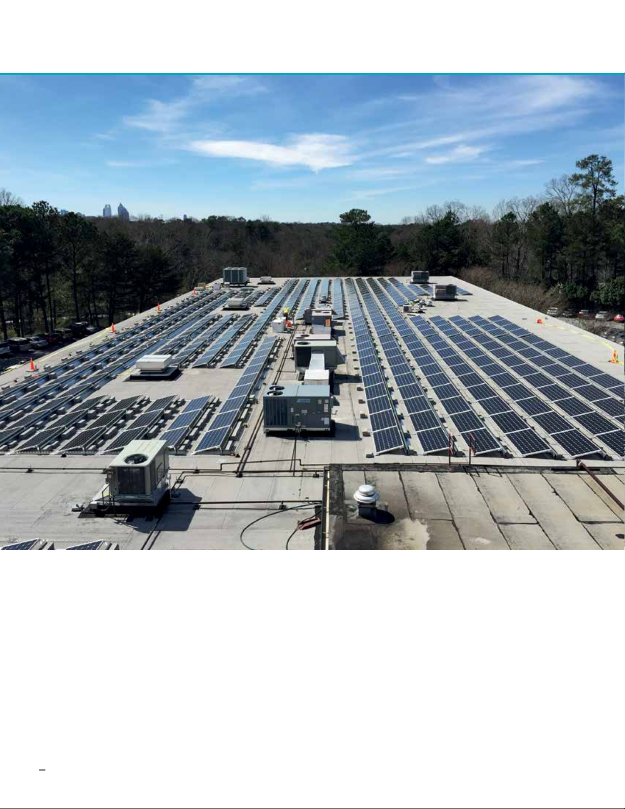
The installation system AEROCOMPACT S is a robust racking
system for mounting PV modules on flat roofs. It consists of
prefabricated aluminum retaining brackets with glued on building
protection pads, deflector plates and all required small parts
that assure a safe installation. This installation system allows
installation on flat roofs with large surfaces and without roof
penetration. This innovative system uses the frame structure and
aerodynamic effects to ensure stability.
AEROCOMPACT S is designed for systems facing south with an
inclination of 5°, 10° and 15°. It can be used for most framed
PV modules of leading manufacturers with following dimension:
AEROCOMPACT S module width x module length
37.4 – 41.3'' x 61.1 – 81.9''
The AEROCOMPACT S5, S10, S15 standard version is designed
for maximum design loads of 50 psf, downforce and uplift. The
AEROCOMPACT Alpine Version is designed for maximum design
loads of 92 psf downforce (uplift unchanged). All Values are
Design-loads as a load combination of dead weight, wind and
snow. Therefore, check the snow load zone of your location
beforehand. The System is wind-tunnel tested, CE certified and
conforms to UL 2703.
Can be used for the following flat-roof coverings:
Foil roof, bitumen roof, Gravel roof, Green roof.
Note: We recommend to remove the gravel and green in the area
where the bracket touches the roof surface.
AEROCOMPACT offers the AeroTool software to design the
mounting system including ballast weights. The programme
creates a project report with the statistically calculation, ballast
weights and system material list.
If you have any other questions, make use of AEROCOMPACT’s
professional and comprehensive consulting service. Our engi-
neers will be happy to help.
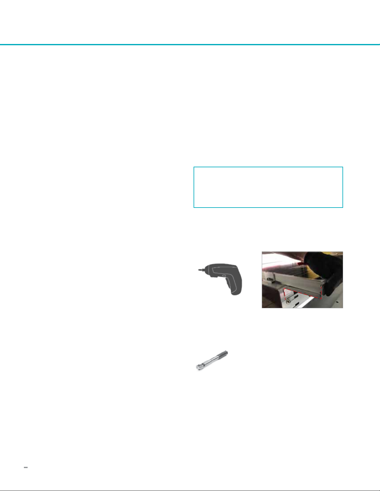
PLEASE MAINTAIN THE FOLLOWING TORQUES WHEN
INSTALLING SCREWS:
133 lbf in
M8 Screw (fixation of module clamps,
wind sheets, ballast trays, and accessories)
REQUIRED TOOLS
Cordless screwdriver spacer bracket (S5 30° only)
Torque wrench

9
SAFETY INFORMATION
It is important that you install person-independent
fall arrest systems or reception system according
to Norm in your Country prior to the start of work!
Occupational Safety Regulation for Construction
Workers and country specific regulations must be
followed!
If person-independent fall arrest systems or re-
ception systems are not available for work-related
reasons then safety harnesses must be used!
Use only safety harnesses (harnesses and catch-
ing belts, connecting ropes/belts, fall absorber,
rope cutter) marked and tested by authorized
testing laboratories.
If person-independent fall arrest systems or recep-
tion systems are not available and safety harness-
es are not used, it can result in falls from great
heights and therefore to severe or deadly injuries!
Leaning ladders can cause dangerous falls, if the
ladder caves in, slips, or falls over!
Work in close proximity of live, electrical overhead
power lines, with which you can come in contact,
only if
- power is turned off and that condition is guaran-
teed for the time of the work
- the parts under power are protected through
covers or barriers.
- the safety distances are not too short.
Radius of voltage:
1 m in 1,000 Volt of voltage
3 m in 1,000 to 11,000 Volts of voltage
4 m in 11,000 to 22,000 Volts of voltage
5 m in 22,000 to 38,000 Volts of voltage
> 5 m if the voltage is unknown
The manufacturer hereby agrees to take back for
recycling all products that are marked with the
eco-label as well as all materials used herein.
Only the approved heat transfer medium may be
used!
If at all possible, the safety harness must be
fastened above the user. Fasten safety harnesses
only on building elements or fastening points that
can carry the load!
Do not use defective ladders, e.g. cracked steps
and rails of wooden ladders, bent and kinked
metal ladders. Do not fix partially broken steps,
rails and braces!
Safely place a leaning ladder. Make sure the
installation angle is correct (68° - 75°). Secure
leaning ladders against sliding, falling, slipping and
sinking e.g. by using enlarged bases, feet braces
of ladders that are adapted to the ground, fasten-
ing devices.
Lean ladders only against secure support points.
Secure ladders in traffic areas with barriers.
Touching live electrical overhead lines can result
in death.
Wear safety goggles when drilling!
Wear safety shoes for the installation!
Wear cut-proof work gloves when installing the
collectors!
Wear a helmet during installation!
10
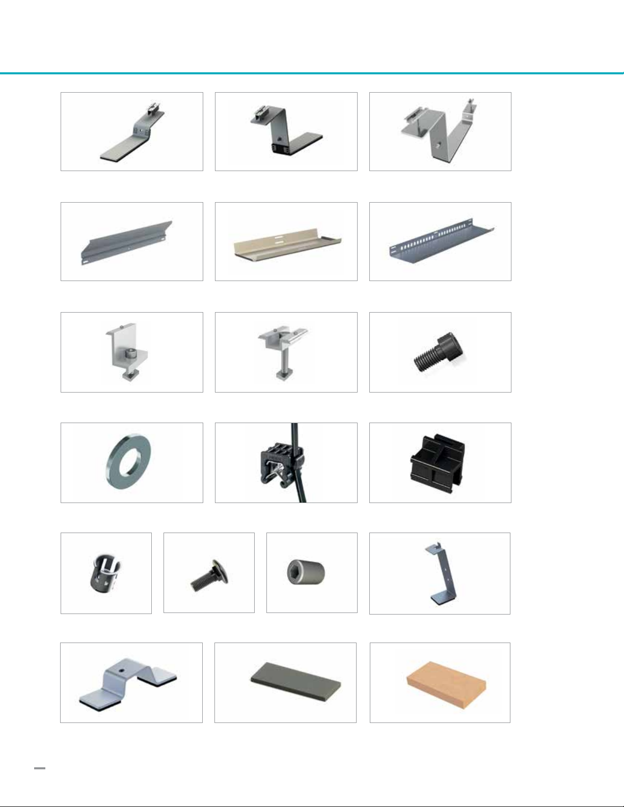
SCOPE OF DELIVERY
Windsheet
Front Bracket
Washer
Ballast Tray
End Bracket
Cable-Tie incl. Clips function
Ballast Tray Long
Connector
Clips for Windsheet
End Clamp
Revet Nut M8 Alpine back Bracket
Middle Clamp Socket Screw M8x30
Flathead Screw
Alpine front Bracket Ballast Block (not included in delivery)
Allenhead Nut
Protection Pad

11
SYSTEM OVERVIEW
Aerocompact
ENDBRACKET
Aerocompact
FRONTBRACKET
Snowload > 2,4 kN
FRONT SUPPORT BRACKET
Snowload > 2,4 kN
BACK SUPPORT BRACKET
Ballast Tray
Aerocompact
CONNECTOR
Ballast Tray
END OR MID CLAMP
PV Module
WINDSHEET
PROTECTION PAD
Rivet NUT M8
Rivet Nut M8
M8 Screw
Ballast Block
16 x 8 x 2 inch
Aerocompact
FRONT SUPPORT BRACKET
END CLAMP
Aerocompact
BACK SUPPORT BRACKET
Screw M8 for Windsheet
suitable for Ballast Tray
and grounding
optional (high snow load) optional (high snow load)

12
INSTALLATION MANUAL
1. Attach the end and middle clamps to the Aerocompact Brackets.
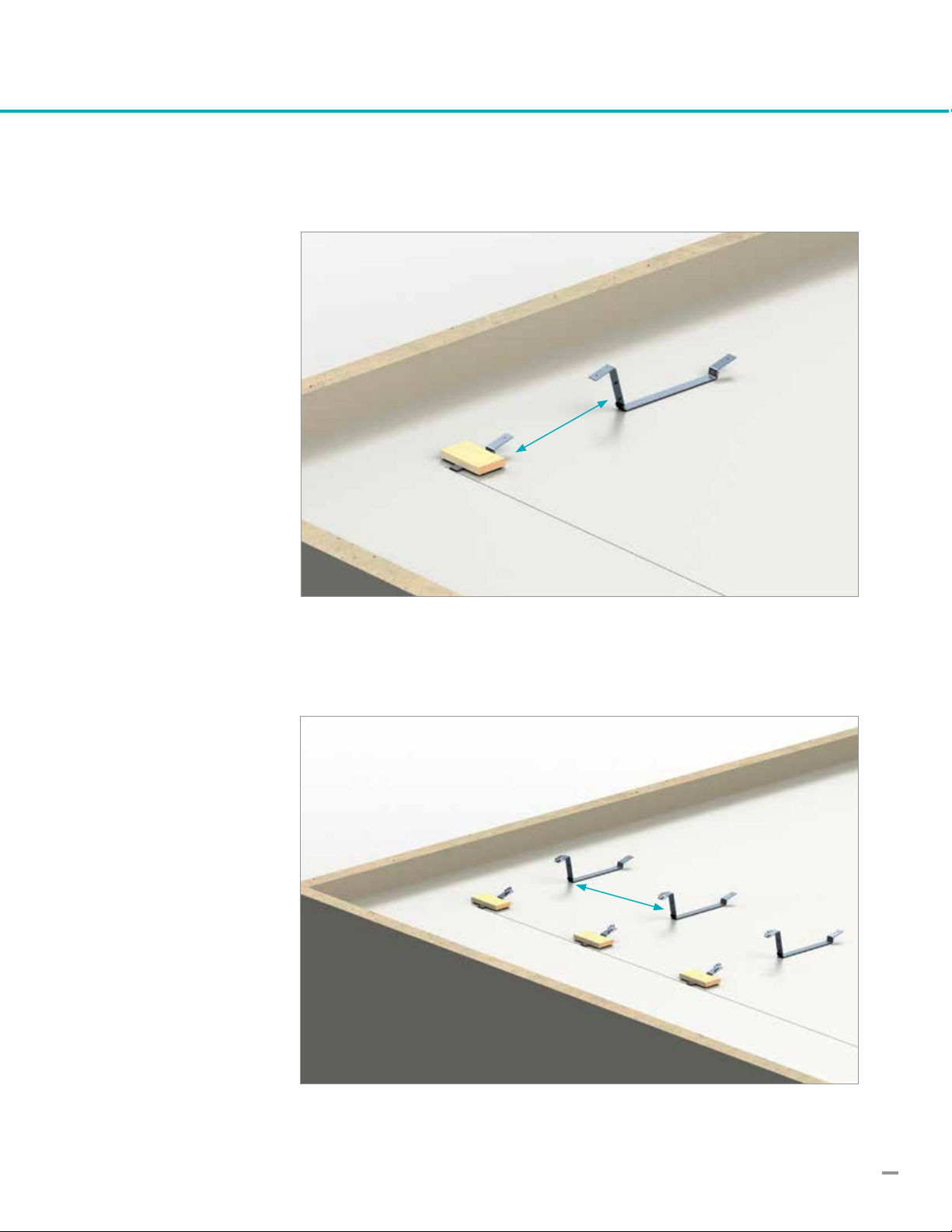
2. Measure the starting point
3. Use chalk line marking
4. Place Front Bracket
5. Attach protection pads to ballast block (Aerocompact
recommends glueing, see p. 22)
6. Secure front bracket with ballast block
13
7. Place the Connector vertically with spacing (module width). The
exact distance is adjusted during module assembly.
Module width
Module length
8. Place the Connector with spacing (module length) in horizontal
position. The exact distance is adjusted during module assembly.
14
9. Mount the module in landscape orientation on the mounting brack-
ets and align flush above the back of the AEROCOMPACT connec-
tor or end bracket. (NOTE: does not apply to S5/30° system,
see p. 22 for use of the spacer bracket)
Tighten the Clamps
10. Subsequently, the end or middle clamps of the previous module can
be tightened and another module placed. At the end of the array end
clamps are attached and tightened after alignment of the last mod-
ule. The clamps must be tightened with 133 lbf in torque value.
11. Clips the cable tie on the module frame for easier
cable management
NOTE
For easy alignment place
the modules on the lower
end on the marking notch.

1515
INSTALLATION of Alpine Version
1. Place the front support bracket (after pre-assembling an end clamp on top) on the lower module end
centered in the middle and tighten.
2. Place back support bracket under
the upper module edge.
Later, after installation of the wind sheet
and ballast tray (if present), insert 2 cage
nuts through ballast tray (if present)
and wind sheet into the bracket.
3. Fix ballast tray (if present) and wind sheet to the support bracket with allen-head screws and washers (torque 133 lbf in).
For snow load of more than 50 psf (design load) additional support brackets must be
installed on the lower and upper end centered of the module.

16
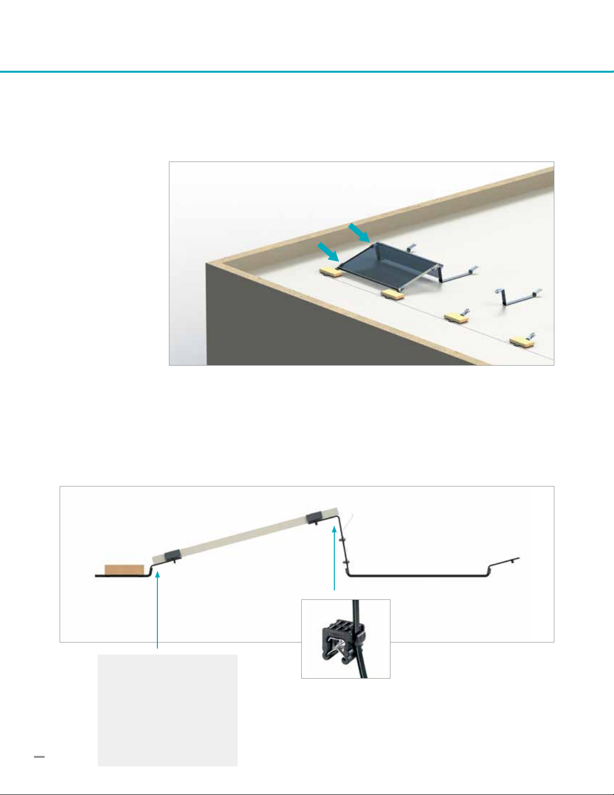
12 . Installation of the Windsheet
The Windsheet is mounted overlapping on the connectors and end brackets, using
allen-head M8x30 screws with washers. These screws are tightened after the
module installation of each row with 133 lbf in.
The windsheet of the S5 systems has a symmetrical cross section, and thus no “wing tip”.
Install it in a way that the slotted holes are close to the upper edge and the rounded holes are
close to the lower edge.
Standard module lengths are covered by two different lengths of wind sheets and ballast trays.
Type Module length
wind sheet / ballast tray 1775 61.1 – 66.7''
wind sheet / ballast tray 2130 72.0 – 81.9''
ATTENTION
In order to keep the installation time low, the windsheet is always simultane-
ously mounted with the ballast trays.
>See installation guideline for ballast tray on the following page.
> Please note in the S5 system (elevation angle 5°) the ballast tray, where
necessary for high ballasting, replaces the wind sheet (see opposite page).
“Wing tip” of the windsheet
pointing upwards (S10, S15)
Fixation of windsheet to
bracket

17
13. Installation of the Ballast Trays
The ballast trays are used as soon as a certain amount of ballast blocks per module is exceed-
ed. Standard (short) or high-load (long) ballast trays may be required, depending on the ballast
amount per module. In static report, these positions are color-coded.
The ballast tray is also used when the point load for the roof membrane is too low. Thus, the
weight is distributed evenly over the module length.
Attach protection pads to each ballast
tray (Aerocompact recommends glueing,
see p.22). The standard (short) tray
requires 2 pads (left and right end),
the long tray requires 4 pads (evenly
distributed over the tray length).
The ballast tray at the front bracket
is mounted with the Flathead Screw
through the square hole. Plug the screw
from behind through the square and
tighten the allen-head nut and the wash-
er. Because of shadowing reasons max.
5 ballast blocks can be installed in the
front ballast tray. Protection Pads
The ballast trays on the connector and
end bracket are installed together with
the windsheet. The standard or short
tray is bolted between the brackets and
the windsheet. The maximum amount
of ballast blocks depends on tray size,
system type (module elevation angle),
and row spacing (shading angle).

18
Install the windsheet clip at the overlap-
ping point of the sheets.
14. Installation of the last row
During assembly of the last row the end
bracket is used instead of the connector.
The installation of the modules, and the
Windsheet / Ballast Tray takes place
the same as before.
End Bracket, last row
NOTE
In case of the S5 systems, wind sheets are
left out where long ballast trays, running
over the whole length of the module, are
present (see p.22).
Long Ballast Tray
Where ballast is high and/or has to be distributed to avoid high point loads, the long ballast tray needs to be installed.
The tray is installed in front of the windsheet (windsheet between bracket and ballast tray) and tightened with the same
screw. The tray is bolted additionally in the center of the windsheet using a cage nut, allen-head screw and washer.

19
NOTE
It is important to ensure that the installed PV system does not impair the effect
of the existing lightning protection system. It is also necessary to ensure that the
PV system is designed that it can be included within the scope of the building
lightning protection system. According to VDE 0185-305-3 supplement 5 to the
separation distance between the PV system and the lightning protection system
must be observed. AEROCOMPACT is not liable for damages that may result from
lightning strikes or grounding issues.
15. Ballasting
Laydown all required ballast blocks according to the static calcula-
tion of the project report on the front, connector and end bracket.
Make sure that all ballast trays, as well as all ballast blocks in direct
contact with the roof surface, are equipped with the adequate num-
ber of protection pads.
The optimal block size for the AEROCOMPACT system is
16 x 8 x 2 inch and a weight of 15 pounds. Choose ballast blocks
that comply with the local weather conditions and have a compres-
sive strength of min. 20.7 MPa or 3,000 psi.
16. Grounding of the Array
ABC
WARNING
Don’t leave the construction site before the modules and wind-sheets
are tightened and all the required ballast blocks are placed according the
project report. Without installation of the windsheets and ballast blocks
the stability of the module array is not guaranteed. The correct position
of the ballast blocks and building protection pads must be checked at
the annual maintenance inspection. It is the responsibility of the installer
to check the required ballast block specification and weight.
NOTE
Option A: Ballast block(s) without tray,
ballast is placed directly on the bracket.
Option B: Ballast tray up to max. 7 blocks.
Option C: Long ballast tray up to max. 16
blocks
After completing the installation, the entire system must be ground-
ed and connected to the in-house lightning protection system.
One grounding connection per module array, comprising up to 120
modules, is recommended. The AEROCOMPACT system needs to be
grounded according to the valid regulations of the country in which
the plant will be built.
Possible connection point (M8 bolt on bracket) for grounding equip-
ment (example).
Please note: if bare copper wire is used for array grounding, make
sure that copper is permanently kept separated from aluminum and
galvanized steel parts to prevent contact corrosion.
Install the grounding lug with the
same screw used for the windsheet
Due to the UL certified grounding
clamps and the UL certification
for the array it is not necessary to
install grounding wires between the
modules.
Grounding
pins

20
Bonding and Grounding
For grounding and /or bonding of PV modules and PV mounting systems, national/regional/
local codes apply (Aerocompact takes no responsibility for grounding/bonding and any other
electrical details). On US territory, ANSI/NFPA 70 sets minimum requirements, to be met by
the following:
Continuous bonding between modules and the mounting system, and thus between all module frames
and racking elements within an array, is achieved by Aerocompact‘s module clamps with intergrated pins.
The performance of these clamps has been tested and recognized for UL listing.
[PV modules lacking UL 1703 certification may require diverging, specific bonding measures, including
individual bonding/grounding of the racking elements.]
Permanent grounding of each PV array, consisting of and interconnected by the com-
ponents mentioned above, must then be accomplished by at least one (sufficient for a
standard array size of 12x10 modules) point of connection to suitable grounding equipment
of the building.
Keep unprotected copper wire separated from aluminum and especially galvanized steel!
Make sure to sustain continuous grounding/bonding during maintenance work!
The module clamp with its grounding pins is re-usable
and need not be replaced after removal during mainte-
nance.
Stainless steel pins integrated in the module clamps provide
bonding of module frames to racking elements; the pins pierce
through the non-conductive surface of the anodized module
frame; tighten module clamps with a torque of 133 lbf in.
Grounding lug for grounding a module array, to be fixed using
M8 bolting hardware, e.g. in suitable holes found in any support
bracket of the mounting system; the lug accepts a range of
copper and aluminum wires.
Stainless steel M8 hardware used to fix windsheets and/or
ballast trays to the racking elements provides bonding of named
components, adding further to the complete bonding between
all tarts within an array; tighten M8 hardware with a torque of
133 lbf in.
possible connection point for
grounding lug
This manual suits for next models
2
Table of contents
Other AEROCOMPACT Inverter manuals


Popular Inverter manuals by other brands

GYS
GYS PSW 600 W Translation of the original instructions

Yamaha
Yamaha EDL20000TE owner's manual

YASKAWA
YASKAWA VARISPEED-616G5 instruction manual

Aurora
Aurora PVI-3.0-OUTD-ZZ Installation and configuration manual

Champion Global Power Equipment
Champion Global Power Equipment 201081 quick start guide

Telefunken
Telefunken TF-PI05 instruction manual


