AEROCOMPACT CompactGROUND G15 User manual
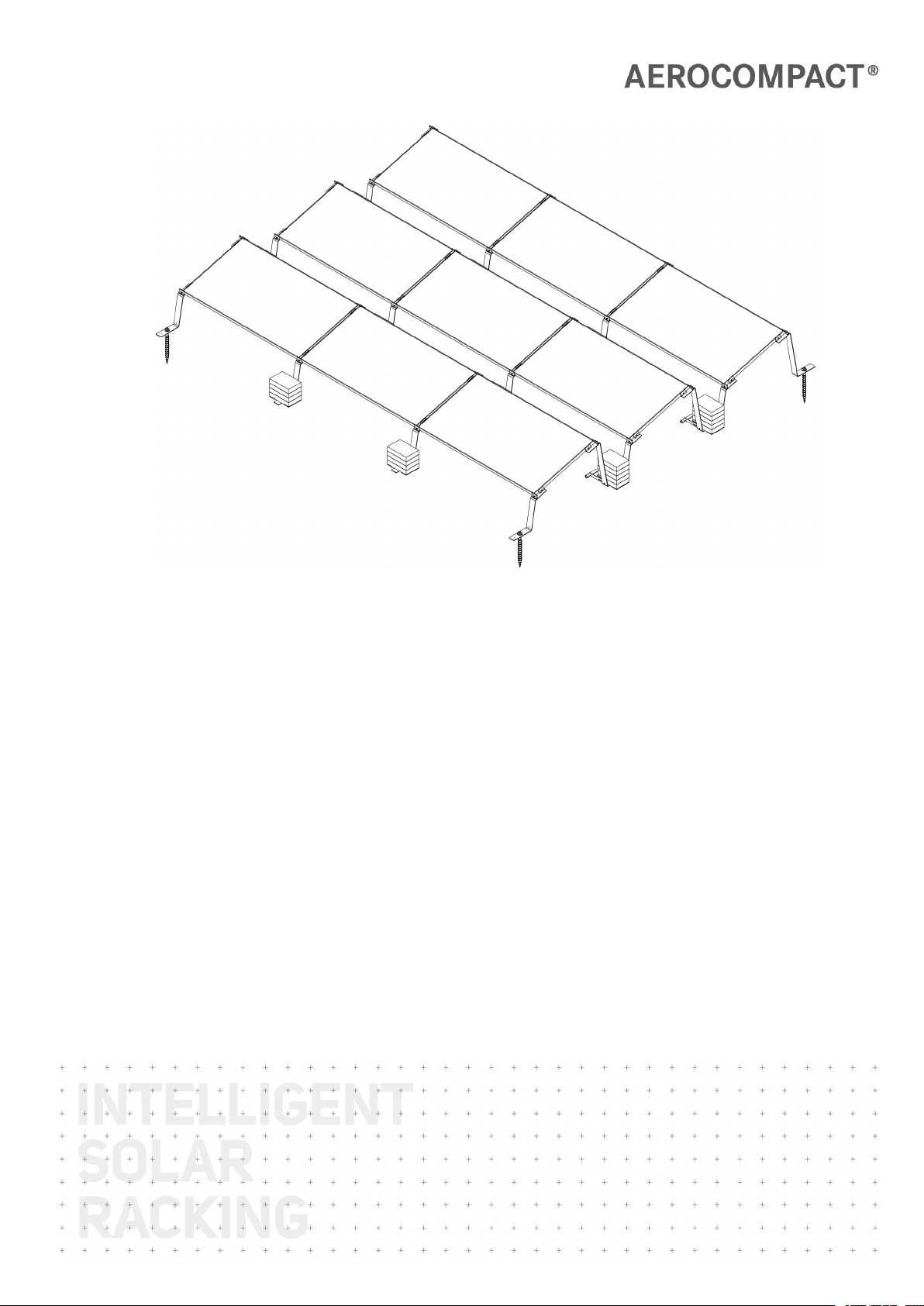
CompactGROUND
G15 | G20
Assembly Instructions
Version: 03/2021
Language: English | Original language: German
Original installation instructions
Important! Read carefully before installation!

G15 | G20
www.aerocompact.com 2
Notice
Subject to changes due to technical improvements. These assembly instructions correspond to the technical
status of the delivered product and not to the current development status of the manufacturer.
If pages or parts of the assembly instructions are missing, please contact the manufacturer's address given
below.
The original language of these assembly instructions is German. Any assembly instructions in another lan-
guage are a translation of the assembly instructions in German.
The assembly instructions are protected by copyright. Without written permission from AEROCOMPACT®
the assembly instructions may not be copied, reproduced, microfilmed, translated or converted for storage
and processing in computer systems, either in part or in full.
Copyright by © AEROCOMPACT®
Manufacturer
AEROCOMPACT® Holding
Sonnenstraße 10
A 6822 Satteins | Austria
office@aerocompact.com
www.aerocompact.com
Update
This manual is subject to change without notice. This does not represent any obligation on the part of the
manufacturer.
Creation date
03/2021
+
+
+
+
+
+
+
+
+
+
+
+
+
+
+
+
+
+
+
+
+
+
+
+
+
+
+
+
+
+
+
+
+
+
+
+
+
+
+
+
+
+
+
+
+
+
+
+
+
+
+
+
+
+
+
+
+
+
+
+
+
+
+
+
+
+
+
+
+
+
+
+
+
+
+
+
+
+
+
+
+
+
+
+
+
+
+
+
+
+
+
+
+
+
+
+
+
+
+
+
+
+
+
+
+
+
+
+
+
+
+
+
+
+
+
+
+
+
+
+
+
+
+
+
+
+
+
+
+
+
+
+
+
+
+
+
+
+
+
+
+
+
+
+
+
+
+
+
+
+
+
+
+
+
+
+
+
+
+
+
+
+
+
+
+
+
+
+
+
+
+
+
+
+
+
+
+
+
+
+
+
+
+
+
+
+
+
+
+
+
+
+
+
+
+
+
+
+
+
+
+
+
+
+
+
+
+
+
+
+
+
+
+
+
+
+
+
+
+
+
+
+
+
+
+
+
+
+
+
+
+
+
+
+
+
+
+
+
+
+
+
+
+
+
+
+
+
+
+
+
+
+

G15 | G20
www.aerocompact.com 3
TOC
About This Document 4
Applicable Documents 4
Explanation of Symbols 4
Symbols in Illustrations 4
Target group 5
Appropriate use 5
Liability, Warranty, Guarantee 5
Planning documents 5
Guarantee 6
General information on liability 7
Systems with clamping on the short module side 7
Safety 8
Requirements of personnel 8
Working safely 8
Weather conditions 8
Dangers from the environment 8
Personal protective equipment (PPE) 8
System Overview 10
Basic components G15 10
Basic components G20 11
Ballasting 12
Accessories 12
Variants 13
Assembly 14
Pre.installing the clamps 14
Measure area, place feet and connectors 15
Installing modules 16
Installing Microinverters - US (optional) 18
Installing Microinverters - EU (optional) 18
Securing the system 18
Option 1: Securing with ground screws 18
Option 2: Ballasting directly on the feet or connectors 19
Option 3: Short ballast tray 19
Option 4: Long ballast tray 20
Installing cable pipe assembly (optional) 21
Mount cable pipe to ballast tray 21
Fasten cable pipes with brackets 22
Maintenance 23
Complete System 23
Fittings 23
Disassembly 24
Disassemble components 24
+
+
+
+
+
+
+
+
+
+
+
+
+
+
+
+
+
+
+
+
+
+
+
+
+
+
+
+
+
+
+
+
+
+
+
+
+
+
+
+
+
+
+
+
+
+
+
+
+
+
+
+
+
+
+
+
+
+
+
+
+
+
+
+
+
+
+
+
+
+
+
+
+
+
+
+
+
+
+
+
+
+
+
+
+
+
+
+
+
+
+
+
+
+
+
+
+
+
+
+
+
+
+
+
+
+
+
+
+
+
+
+
+
+
+
+
+
+
+
+
+
+
+
+
+
+
+
+
+
+
+
+
+
+
+
+
+
+
+
+
+
+
+
+
+
+
+
+
+
+
+
+
+
+
+
+
+
+
+
+
+
+
+
+
+
+
+
+
+
+
+
+
+
+
+
+
+
+
+
+
+
+
+
+
+
+
+
+
+
+
+
+
+
+
+
+
+
+
+
+
+
+
+
+
+
+
+
+
+
+
+
+
+
+
+
+
+
+
+
+
+
+
+
+
+
+
+
+
+
+
+
+
+
+
+
+
+
+
+
+
+
+
+
+
+
+
+
+
+
+
+
+
G15 | G20
About This Document
www.aerocompact.com 4
ABOUT THIS DOCUMENT
These installation instructions describe the procedure for installing the product. Read these assembly instruc-
tions carefully before starting the assembly. Follow the instructions carefully to ensure correct installation of
the product.
Applicable Documents
The following documents are a part of these installation instructions and are absolutely necessary for the
correct assembly of the system:
oProject report from AEROTOOL
oPlanning documents and drawings
Explanation of Symbols
In order to make these assembly instructions easy to understand, uniform safety instructions, symbols, terms
and abbreviations are used. The following symbols indicate notes which are not relevant to safety, but
which make working with the assembly instructions easier.
Requirements for an action are depicted with this symbol. Make sure that all requirements are met before
you carry out the following actions.
Action steps are depicted with this symbol. Carry out the steps in the specified order.
The result of the action is depicted with this symbol.
This note provides useful information for a smooth assembly of the product.
Symbols in Illustrations
Activities
Certain activities are required to carry out the assembly. These activities are shown in the illustrations with
the following symbols.
Check AEROTOOL planning documents Visual inspection
Activity by hand Observe right angle
Optional component,
optional installation method
+
+
+
+
+
+
+
+
+
+
+
+
+
+
+
+
+
+
+
+
+
+
+
+
+
+
+
+
+
+
+
+
+
+
+
+
+
+
+
+
+
+
+
+
+
+
+
+
+
+
+
+
+
+
+
+
+
+
+
+
+
+
+
+
+
+
+
+
+
+
+
+
+
+
+
+
+
+
+
+
+
+
+
+
+
+
+
+
+
+
+
+
+
+
+
+
+
+
+
+
+
+
+
+
+
+
+
+
+
+
+
+
+
+
+
+
+
+
+
+
+
+
+
+
+
+
+
+
+
+
+
+
+
+
+
+
+
+
+
+
+
+
+
+
+
+
+
+
+
+
+
+
+
+
+
+
+
+
+
+
+
+
+
+
+
+
+
+
+
+
+
+
+
+
+
+
+
+
+
+
+
+
+
+
+
+
+
+
+
+
+
+
+
+
+
+
+
+
+
+
+
+
+
+
+
+
+
+
+
+
+
+
+
+
+
+
+
+
+
+
+
+
+
+
+
+
+
+
+
+
+
+
+
+
+
+
+
+
+
+
+
+
+
+
+
+
+
+
+
+
+
+

G15 | G20
About This Document
www.aerocompact.com 5
Tools
Certain tools are required to carry out the assembly. These tools are shown in the illustrations with the fol-
lowing symbols.
Measuring tape, measure Cordless screwdriver, screwdriver
Pencil, mark Torque wrench,
Observe torque
Chalk line
Target group
These installation instructions are intended for trained personnel who are familiar with the installation of
photovoltaic systems. The personnel should also be familiar with working on roofs and know the local reg-
ulations regarding work safety. The personnel must also observe the instructions in the Safety chapter.
Appropriate use
The CompactGROUND ground-mounted system is designed for installing PV modules on the ground. The
slope must not exceed 10° (ballasting with ballast stones and/or ground screws). A project specific cla-
rification is required for a slope inclination of more than 10°. The system must be properly installed in accord-
ance with these installation instructions and the planning documents supplied.
PV modules used with the CompactGROUND system should be approved by the module manufacturer.
AEROCOMPACT accepts no liability for loss of performance or damage of any kind to the PV modules.
Any other use of the CompactGROUND system is considered improper.
Liability, Warranty, Guarantee
These assembly instructions and the project report supplied with the product are integral parts of the
product. The information, data and instructions given in the assembly instructions were up to date at the
time of printing. No claims can be made for products already delivered that deviate from the information,
illustrations and descriptions.
The project report supplied with the system contains the static calculation related to the location. The pos-
ition of the modules on the ground, the number and position of the ground screws and/or ballasting must
be followed exactly as specified in the project report. The Aerocompact system is designed and planned with
the Aerotool software.
Planning documents
Before installation, check that the site conditions correspond to the planning document details.
This includes:
+
+
+
+
+
+
+
+
+
+
+
+
+
+
+
+
+
+
+
+
+
+
+
+
+
+
+
+
+
+
+
+
+
+
+
+
+
+
+
+
+
+
+
+
+
+
+
+
+
+
+
+
+
+
+
+
+
+
+
+
+
+
+
+
+
+
+
+
+
+
+
+
+
+
+
+
+
+
+
+
+
+
+
+
+
+
+
+
+
+
+
+
+
+
+
+
+
+
+
+
+
+
+
+
+
+
+
+
+
+
+
+
+
+
+
+
+
+
+
+
+
+
+
+
+
+
+
+
+
+
+
+
+
+
+
+
+
+
+
+
+
+
+
+
+
+
+
+
+
+
+
+
+
+
+
+
+
+
+
+
+
+
+
+
+
+
+
+
+
+
+
+
+
+
+
+
+
+
+
+
+
+
+
+
+
+
+
+
+
+
+
+
+
+
+
+
+
+
+
+
+
+
+
+
+
+
+
+
+
+
+
+
+
+
+
+
+
+
+
+
+
+
+
+
+
+
+
+
+
+
+
+
+
+
+
+
+
+
+
+
+
+
+
+
+
+
+
+
+
+
+
+

G15 | G20
About This Document
www.aerocompact.com 6
oThe site
oThe surroundings and the topography of the site
oDimensions, surface and ground composition
oPosition and size of obstacles (terrain levels, existing or planned pipeline routes, traffic routes and
other structures, etc.)
oDrainage features
oSite preparation, i.e. grading, if necessary
If in doubt, measure the friction between the system components and the ground surface to validate the
assumptions made in the design documents. If the project details in the planning documents do not match
the values on-site, contact the responsible planner. This is especially true if the planning is not based on
detailed and up-to-date data collection on-site.
Ensure that the weight and dimensions of the ballast blocks are in accordance with the planning doc-
uments. The ballast plans from AEROTOOL are optimized for specific block characteristics. If the block spe-
cified in the design report is not used, then a revised ballast plan will be needed.
The selection and procurement of the ballast blocks must be handled by the customer. Ensure that the bal-
last blocks have sufficient density to remain stable under local conditions over the lifetime of the PV system.
Before using ground screws, ensure that their entire length can be permanently anchored in the ground.
Caution against the following should be taken:
oHazards from contaminated sites
oIncreased risk of corrosion due to high groundwater level and/or aggressive soil chemistry (strongly
acidic or alkaline reaction).
oRestrictions on anchorage depth, e.g. in the soil depth above the cap of a landfill, excessive content
of stones and boulders (which may require pre-drilling).
If the anchorage depth is limited, a shorter ground screw with a length of 10 inches (280 mm) can be used
instead of the standard 18 inch (460 mm) ground screw. If a shorter ground screw (lower load capacity)
must be used in place of the standard ground screw, then a new statics plan is required.
Aerocompact accepts no liability for damage and malfunctions caused by:
oimproper use
ouse of non-certified components.
ounauthorized modifications to the product.
oimproper handling of the product.
oInstallation errors
oFailure to comply with the installation instructions or planning documents.
Guarantee
The warranty period for the system is 25 years. The warranty period for galvanized steel parts is 10 years. The
guarantee is only valid if the installation is carried out professionally and all system components are pur-
chased from Aerocompact. If the assembly instructions or the planning documents are disregarded, the war-
ranty will be invalidated.
+
+
+
+
+
+
+
+
+
+
+
+
+
+
+
+
+
+
+
+
+
+
+
+
+
+
+
+
+
+
+
+
+
+
+
+
+
+
+
+
+
+
+
+
+
+
+
+
+
+
+
+
+
+
+
+
+
+
+
+
+
+
+
+
+
+
+
+
+
+
+
+
+
+
+
+
+
+
+
+
+
+
+
+
+
+
+
+
+
+
+
+
+
+
+
+
+
+
+
+
+
+
+
+
+
+
+
+
+
+
+
+
+
+
+
+
+
+
+
+
+
+
+
+
+
+
+
+
+
+
+
+
+
+
+
+
+
+
+
+
+
+
+
+
+
+
+
+
+
+
+
+
+
+
+
+
+
+
+
+
+
+
+
+
+
+
+
+
+
+
+
+
+
+
+
+
+
+
+
+
+
+
+
+
+
+
+
+
+
+
+
+
+
+
+
+
+
+
+
+
+
+
+
+
+
+
+
+
+
+
+
+
+
+
+
+
+
+
+
+
+
+
+
+
+
+
+
+
+
+
+
+
+
+
+
+
+
+
+
+
+
+
+
+
+
+
+
+
+
+
+
+

G15 | G20
About This Document
www.aerocompact.com 7
Photovoltaic racking systems are not maintenance-free. Carry out maintenance annually and immediately
after unusual weather events, e.g., after heavy storms or heavy snowfall, etc. If the maintenance is not carried
out at the specified interval, the warranty will become void.
General information on liability
The ground mount system is sold within the framework of a purchase agreement. Assembly/installation by
the purchaser or third parties is not carried out on behalf of or for Aerocompact and must be carried out by
qualified personnel strictly in accordance with the installation instructions. The Aerocompact system must
be designed and planned with the AEROTOOL software. Aerocompact is not responsible for the project-
related construction of the ground or ground surface or for its professional execution.
Errors and damage as well as limited or insufficient functionality of the system due to incorrect installation
and/or installation that deviates from the installation instructions and/or the project report (AEROTOOL)
exclude any material defect for which Aerocompact is responsible. In the event of improper handling, the
rights of the buyer due to a material defect shall expire. The system warranty is only valid if all system com-
ponents are purchased from Aerocompact.
Each change must be approved by the responsible planner. Unauthorized deviations from the plans will res-
ult in loss of warranty and exclusion of liability in the event of property damage or personal injury.
Systems with clamping on the short module side
For a system with a clamp on the short side of the module, it is assumed that the module may also be used
in this mounting form (clamp on the short sides of the module). This approval can either be generally avail-
able as part of the module certification or, under certain circumstances, can also be given by the module
manufacturer on a project-specific basis.
+
+
+
+
+
+
+
+
+
+
+
+
+
+
+
+
+
+
+
+
+
+
+
+
+
+
+
+
+
+
+
+
+
+
+
+
+
+
+
+
+
+
+
+
+
+
+
+
+
+
+
+
+
+
+
+
+
+
+
+
+
+
+
+
+
+
+
+
+
+
+
+
+
+
+
+
+
+
+
+
+
+
+
+
+
+
+
+
+
+
+
+
+
+
+
+
+
+
+
+
+
+
+
+
+
+
+
+
+
+
+
+
+
+
+
+
+
+
+
+
+
+
+
+
+
+
+
+
+
+
+
+
+
+
+
+
+
+
+
+
+
+
+
+
+
+
+
+
+
+
+
+
+
+
+
+
+
+
+
+
+
+
+
+
+
+
+
+
+
+
+
+
+
+
+
+
+
+
+
+
+
+
+
+
+
+
+
+
+
+
+
+
+
+
+
+
+
+
+
+
+
+
+
+
+
+
+
+
+
+
+
+
+
+
+
+
+
+
+
+
+
+
+
+
+
+
+
+
+
+
+
+
+
+
+
+
+
+
+
+
+
+
+
+
+
+
+
+
+
+
+
+

G15 | G20
Safety
www.aerocompact.com 8
SAFETY
Requirements of personnel
The person must be physically and mentally fit. Under no circumstances must the installation personnel be
under the influence of medication, alcohol or drugs.
Persons who are not healthy and fit must not work on roofs.
Personnel who are in training must only carry out work under the supervision of qualified personnel who
are authorized to train personnel.
Working safely
The company carrying out the installation is responsible for ensuring that the local regulations for work
safety and accident prevention are observed.
Weather conditions
In the event of unsuitable weather, work shall not be continued longer than necessary or shall not be started
at all.
Never carry out assembly work in strong winds. Strong wind exerts enormous forces on the large-area PV
modules. There is a risk of personal injury from a blown module.
Dangers from the environment
Keep sufficient distance from overhead electrical lines. The following distances must be observed:
1 m to 1,000 V
3 m: 1,000 to 11,000 V
4 m: 11,000 to 22,000 V
5 m: 22,000 to 38,000 V
> 5 m: if the voltage is unknown
Personal protective equipment (PPE)
Personal protective equipment is required to prevent injuries during assembly work.
+
+
+
+
+
+
+
+
+
+
+
+
+
+
+
+
+
+
+
+
+
+
+
+
+
+
+
+
+
+
+
+
+
+
+
+
+
+
+
+
+
+
+
+
+
+
+
+
+
+
+
+
+
+
+
+
+
+
+
+
+
+
+
+
+
+
+
+
+
+
+
+
+
+
+
+
+
+
+
+
+
+
+
+
+
+
+
+
+
+
+
+
+
+
+
+
+
+
+
+
+
+
+
+
+
+
+
+
+
+
+
+
+
+
+
+
+
+
+
+
+
+
+
+
+
+
+
+
+
+
+
+
+
+
+
+
+
+
+
+
+
+
+
+
+
+
+
+
+
+
+
+
+
+
+
+
+
+
+
+
+
+
+
+
+
+
+
+
+
+
+
+
+
+
+
+
+
+
+
+
+
+
+
+
+
+
+
+
+
+
+
+
+
+
+
+
+
+
+
+
+
+
+
+
+
+
+
+
+
+
+
+
+
+
+
+
+
+
+
+
+
+
+
+
+
+
+
+
+
+
+
+
+
+
+
+
+
+
+
+
+
+
+
+
+
+
+
+
+
+
+
+

G15 | G20
Safety
www.aerocompact.com 9
Wear protective goggles when drilling.
Wear safety boots.
Wear cut-resistant work gloves during assembly.
Helmets are required for all persons involved on the construction site.
+
+
+
+
+
+
+
+
+
+
+
+
+
+
+
+
+
+
+
+
+
+
+
+
+
+
+
+
+
+
+
+
+
+
+
+
+
+
+
+
+
+
+
+
+
+
+
+
+
+
+
+
+
+
+
+
+
+
+
+
+
+
+
+
+
+
+
+
+
+
+
+
+
+
+
+
+
+
+
+
+
+
+
+
+
+
+
+
+
+
+
+
+
+
+
+
+
+
+
+
+
+
+
+
+
+
+
+
+
+
+
+
+
+
+
+
+
+
+
+
+
+
+
+
+
+
+
+
+
+
+
+
+
+
+
+
+
+
+
+
+
+
+
+
+
+
+
+
+
+
+
+
+
+
+
+
+
+
+
+
+
+
+
+
+
+
+
+
+
+
+
+
+
+
+
+
+
+
+
+
+
+
+
+
+
+
+
+
+
+
+
+
+
+
+
+
+
+
+
+
+
+
+
+
+
+
+
+
+
+
+
+
+
+
+
+
+
+
+
+
+
+
+
+
+
+
+
+
+
+
+
+
+
+
+
+
+
+
+
+
+
+
+
+
+
+
+
+
+
+
+
+

G15 | G20
System Overview
www.aerocompact.com 10
SYSTEM OVERVIEW
Basic components G15
1End clamp, varying clamp height for 30 - 50 mm frame heights | CLEG10-XX
2Back foot G15 | G15EB
3Connector G15, shading angle EU18°/US25° | G15CNL, G15CNS
4Front foot G15, | G15FB
5Middle clamp, for 30 - 50 mm frame heights | CLMG10
+
+
+
+
+
+
+
+
+
+
+
+
+
+
+
+
+
+
+
+
+
+
+
+
+
+
+
+
+
+
+
+
+
+
+
+
+
+
+
+
+
+
+
+
+
+
+
+
+
+
+
+
+
+
+
+
+
+
+
+
+
+
+
+
+
+
+
+
+
+
+
+
+
+
+
+
+
+
+
+
+
+
+
+
+
+
+
+
+
+
+
+
+
+
+
+
+
+
+
+
+
+
+
+
+
+
+
+
+
+
+
+
+
+
+
+
+
+
+
+
+
+
+
+
+
+
+
+
+
+
+
+
+
+
+
+
+
+
+
+
+
+
+
+
+
+
+
+
+
+
+
+
+
+
+
+
+
+
+
+
+
+
+
+
+
+
+
+
+
+
+
+
+
+
+
+
+
+
+
+
+
+
+
+
+
+
+
+
+
+
+
+
+
+
+
+
+
+
+
+
+
+
+
+
+
+
+
+
+
+
+
+
+
+
+
+
+
+
+
+
+
+
+
+
+
+
+
+
+
+
+
+
+
+
+
+
+
+
+
+
+
+
+
+
+
+
+
+
+
+
+
+

G15 | G20
System Overview
www.aerocompact.com 11
Basic components G20
1End clamp, varying clamp height for 30 - 50 mm frame heights | CLEG10-XX
2Back foot G20 | G20EB
3Connector G20, shading angle EU18°/US25° | G20CNL, G20CNS
4Front foot G20, | G20FB
5Middle clamp, for 30 - 50 mm frame heights | CLMG10
+
+
+
+
+
+
+
+
+
+
+
+
+
+
+
+
+
+
+
+
+
+
+
+
+
+
+
+
+
+
+
+
+
+
+
+
+
+
+
+
+
+
+
+
+
+
+
+
+
+
+
+
+
+
+
+
+
+
+
+
+
+
+
+
+
+
+
+
+
+
+
+
+
+
+
+
+
+
+
+
+
+
+
+
+
+
+
+
+
+
+
+
+
+
+
+
+
+
+
+
+
+
+
+
+
+
+
+
+
+
+
+
+
+
+
+
+
+
+
+
+
+
+
+
+
+
+
+
+
+
+
+
+
+
+
+
+
+
+
+
+
+
+
+
+
+
+
+
+
+
+
+
+
+
+
+
+
+
+
+
+
+
+
+
+
+
+
+
+
+
+
+
+
+
+
+
+
+
+
+
+
+
+
+
+
+
+
+
+
+
+
+
+
+
+
+
+
+
+
+
+
+
+
+
+
+
+
+
+
+
+
+
+
+
+
+
+
+
+
+
+
+
+
+
+
+
+
+
+
+
+
+
+
+
+
+
+
+
+
+
+
+
+
+
+
+
+
+
+
+
+
+

G15 | G20
System Overview
www.aerocompact.com 12
Ballasting
1Long ballast tray | BT-1800, BT-2050, BT-2300
2Short ballast tray | BT-880
3Ground Screw 18 in. | GSC 1.75 in.x18 in.
Accessories
1Cable conduit | CP-430, CP-620, CP-840
2Bracket for cable conduit | BR-CP
3Cable tie clip to module | CLP-M
+
+
+
+
+
+
+
+
+
+
+
+
+
+
+
+
+
+
+
+
+
+
+
+
+
+
+
+
+
+
+
+
+
+
+
+
+
+
+
+
+
+
+
+
+
+
+
+
+
+
+
+
+
+
+
+
+
+
+
+
+
+
+
+
+
+
+
+
+
+
+
+
+
+
+
+
+
+
+
+
+
+
+
+
+
+
+
+
+
+
+
+
+
+
+
+
+
+
+
+
+
+
+
+
+
+
+
+
+
+
+
+
+
+
+
+
+
+
+
+
+
+
+
+
+
+
+
+
+
+
+
+
+
+
+
+
+
+
+
+
+
+
+
+
+
+
+
+
+
+
+
+
+
+
+
+
+
+
+
+
+
+
+
+
+
+
+
+
+
+
+
+
+
+
+
+
+
+
+
+
+
+
+
+
+
+
+
+
+
+
+
+
+
+
+
+
+
+
+
+
+
+
+
+
+
+
+
+
+
+
+
+
+
+
+
+
+
+
+
+
+
+
+
+
+
+
+
+
+
+
+
+
+
+
+
+
+
+
+
+
+
+
+
+
+
+
+
+
+
+
+
+
G15 | G20
System Overview
www.aerocompact.com 13
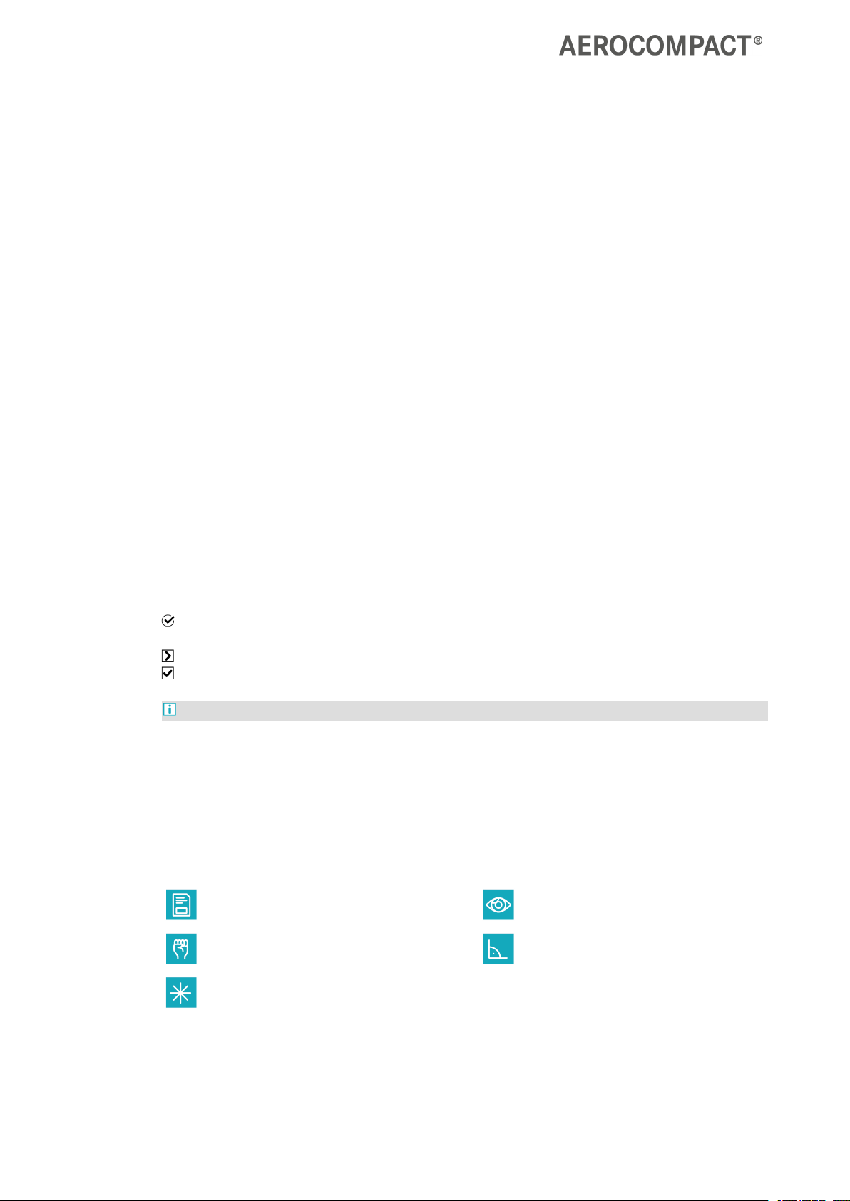
Variants
System G15 xx in. inter-row | EU18° shading angle | 15.75 in. ground clearance
System G15 xx in. inter-row | US 25° shading angle | 15.75 in. ground clearance
System G20 xx in. inter-row | EU18° shading angle | 12.52 in. ground clearance
System G20 xx in. inter-row | US 25° shading angle | 12.52 in. ground clearance
+
+
+
+
+
+
+
+
+
+
+
+
+
+
+
+
+
+
+
+
+
+
+
+
+
+
+
+
+
+
+
+
+
+
+
+
+
+
+
+
+
+
+
+
+
+
+
+
+
+
+
+
+
+
+
+
+
+
+
+
+
+
+
+
+
+
+
+
+
+
+
+
+
+
+
+
+
+
+
+
+
+
+
+
+
+
+
+
+
+
+
+
+
+
+
+
+
+
+
+
+
+
+
+
+
+
+
+
+
+
+
+
+
+
+
+
+
+
+
+
+
+
+
+
+
+
+
+
+
+
+
+
+
+
+
+
+
+
+
+
+
+
+
+
+
+
+
+
+
+
+
+
+
+
+
+
+
+
+
+
+
+
+
+
+
+
+
+
+
+
+
+
+
+
+
+
+
+
+
+
+
+
+
+
+
+
+
+
+
+
+
+
+
+
+
+
+
+
+
+
+
+
+
+
+
+
+
+
+
+
+
+
+
+
+
+
+
+
+
+
+
+
+
+
+
+
+
+
+
+
+
+
+
+
+
+
+
+
+
+
+
+
+
+
+
+
+
+
+
+
+
+
G15 | G20
Assembly
www.aerocompact.com 14
ASSEMBLY
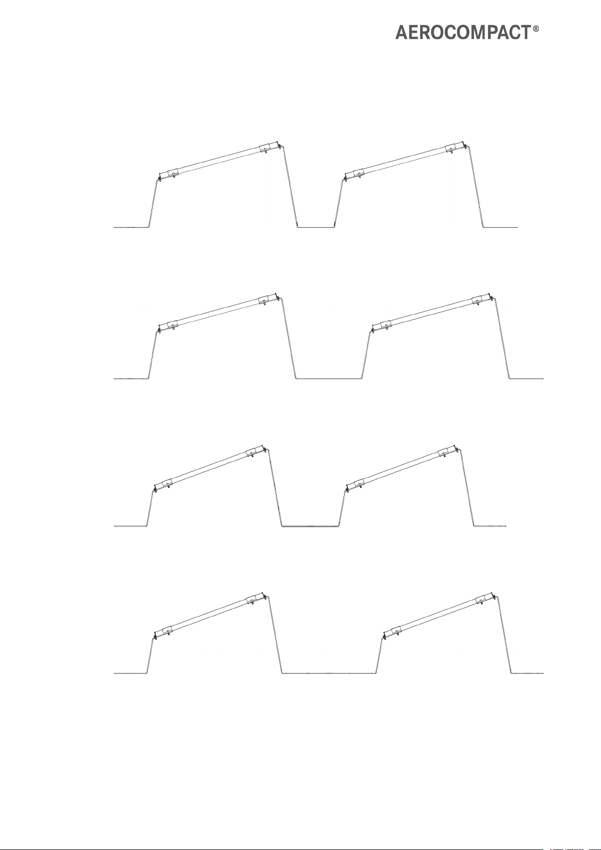
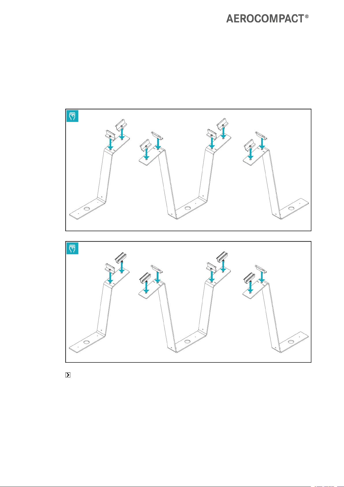
Pre.installing the clamps
Attach end or middle clamps to the front feet, back feet, and connectors as needed.
+
+
+
+
+
+
+
+
+
+
+
+
+
+
+
+
+
+
+
+
+
+
+
+
+
+
+
+
+
+
+
+
+
+
+
+
+
+
+
+
+
+
+
+
+
+
+
+
+
+
+
+
+
+
+
+
+
+
+
+
+
+
+
+
+
+
+
+
+
+
+
+
+
+
+
+
+
+
+
+
+
+
+
+
+
+
+
+
+
+
+
+
+
+
+
+
+
+
+
+
+
+
+
+
+
+
+
+
+
+
+
+
+
+
+
+
+
+
+
+
+
+
+
+
+
+
+
+
+
+
+
+
+
+
+
+
+
+
+
+
+
+
+
+
+
+
+
+
+
+
+
+
+
+
+
+
+
+
+
+
+
+
+
+
+
+
+
+
+
+
+
+
+
+
+
+
+
+
+
+
+
+
+
+
+
+
+
+
+
+
+
+
+
+
+
+
+
+
+
+
+
+
+
+
+
+
+
+
+
+
+
+
+
+
+
+
+
+
+
+
+
+
+
+
+
+
+
+
+
+
+
+
+
+
+
+
+
+
+
+
+
+
+
+
+
+
+
+
+
+
+
+

G15 | G20
Assembly
www.aerocompact.com 15
Measure area, place feet and connectors
Take the dimensions of the array field from the planning documents.
Measure the length of the array field and mark the line.
Measure the width of the array field and mark the line.
Place feet and connectors in the array field :
Vertical field edge: Place starting feet, end feet and connectors with end clamps pre-installed.
Field interior: Place starting feet, end feet and connectors with middle clamps pre-installed.
+
+
+
+
+
+
+
+
+
+
+
+
+
+
+
+
+
+
+
+
+
+
+
+
+
+
+
+
+
+
+
+
+
+
+
+
+
+
+
+
+
+
+
+
+
+
+
+
+
+
+
+
+
+
+
+
+
+
+
+
+
+
+
+
+
+
+
+
+
+
+
+
+
+
+
+
+
+
+
+
+
+
+
+
+
+
+
+
+
+
+
+
+
+
+
+
+
+
+
+
+
+
+
+
+
+
+
+
+
+
+
+
+
+
+
+
+
+
+
+
+
+
+
+
+
+
+
+
+
+
+
+
+
+
+
+
+
+
+
+
+
+
+
+
+
+
+
+
+
+
+
+
+
+
+
+
+
+
+
+
+
+
+
+
+
+
+
+
+
+
+
+
+
+
+
+
+
+
+
+
+
+
+
+
+
+
+
+
+
+
+
+
+
+
+
+
+
+
+
+
+
+
+
+
+
+
+
+
+
+
+
+
+
+
+
+
+
+
+
+
+
+
+
+
+
+
+
+
+
+
+
+
+
+
+
+
+
+
+
+
+
+
+
+
+
+
+
+
+
+
+
+
G15 | G20
Assembly
www.aerocompact.com 16
Installing modules
Hold the front foot in place with a ballast block .
Place the module on the front feet and connectors .
Align the module with the marks on the feet/connectors.
Tighten the screws of the side end clamps to 15 Nm or 11 ft lbs.
+
+
+
+
+
+
+
+
+
+
+
+
+
+
+
+
+
+
+
+
+
+
+
+
+
+
+
+
+
+
+
+
+
+
+
+
+
+
+
+
+
+
+
+
+
+
+
+
+
+
+
+
+
+
+
+
+
+
+
+
+
+
+
+
+
+
+
+
+
+
+
+
+
+
+
+
+
+
+
+
+
+
+
+
+
+
+
+
+
+
+
+
+
+
+
+
+
+
+
+
+
+
+
+
+
+
+
+
+
+
+
+
+
+
+
+
+
+
+
+
+
+
+
+
+
+
+
+
+
+
+
+
+
+
+
+
+
+
+
+
+
+
+
+
+
+
+
+
+
+
+
+
+
+
+
+
+
+
+
+
+
+
+
+
+
+
+
+
+
+
+
+
+
+
+
+
+
+
+
+
+
+
+
+
+
+
+
+
+
+
+
+
+
+
+
+
+
+
+
+
+
+
+
+
+
+
+
+
+
+
+
+
+
+
+
+
+
+
+
+
+
+
+
+
+
+
+
+
+
+
+
+
+
+
+
+
+
+
+
+
+
+
+
+
+
+
+
+
+
+
+
+

G15 | G20
Assembly
www.aerocompact.com 17
Place the next module .
Tighten the screws on the middle clamps of the previous module with 15 Nm or 11 ft lbs..
Tighten the screws on the upper and lower end clamps of the previous module to 15 Nm or 11 ft lbs.
Install remaining modules according to the recommended sequence.
Tighten the screws of the end clamps with 15 Nm or 11 ft lb each.
+
+
+
+
+
+
+
+
+
+
+
+
+
+
+
+
+
+
+
+
+
+
+
+
+
+
+
+
+
+
+
+
+
+
+
+
+
+
+
+
+
+
+
+
+
+
+
+
+
+
+
+
+
+
+
+
+
+
+
+
+
+
+
+
+
+
+
+
+
+
+
+
+
+
+
+
+
+
+
+
+
+
+
+
+
+
+
+
+
+
+
+
+
+
+
+
+
+
+
+
+
+
+
+
+
+
+
+
+
+
+
+
+
+
+
+
+
+
+
+
+
+
+
+
+
+
+
+
+
+
+
+
+
+
+
+
+
+
+
+
+
+
+
+
+
+
+
+
+
+
+
+
+
+
+
+
+
+
+
+
+
+
+
+
+
+
+
+
+
+
+
+
+
+
+
+
+
+
+
+
+
+
+
+
+
+
+
+
+
+
+
+
+
+
+
+
+
+
+
+
+
+
+
+
+
+
+
+
+
+
+
+
+
+
+
+
+
+
+
+
+
+
+
+
+
+
+
+
+
+
+
+
+
+
+
+
+
+
+
+
+
+
+
+
+
+
+
+
+
+
+
+

G15 | G20
Assembly
www.aerocompact.com 18
Installing Microinverters - US (optional)
The microinverter can be installed directly on the module.
Observe the manufacturer's specifications (PV module, microinverter) during installation.
Install the Solar-ClamP according to the manufacturer's instructions.
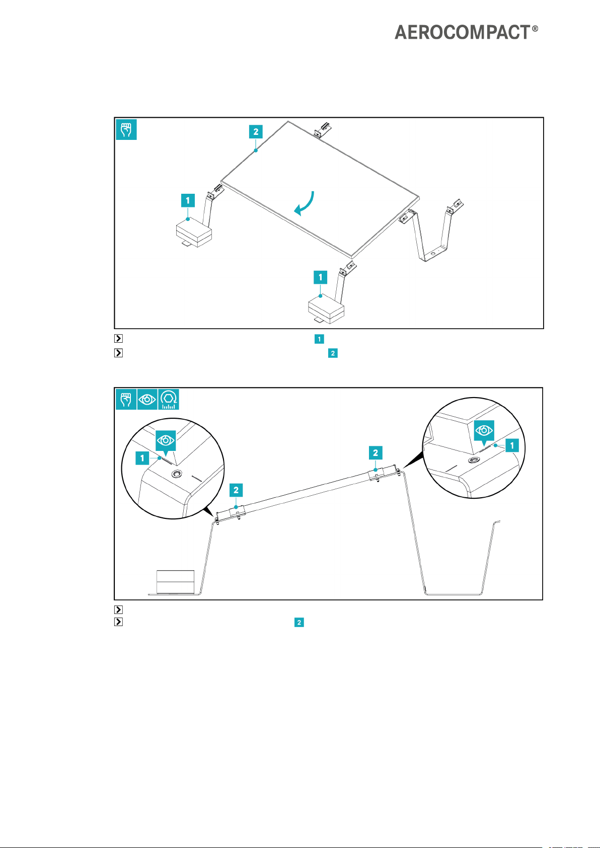
Installing Microinverters - EU (optional)
The microinverter can be mounted below the module on a foot or on a support.
Install the microinverter on the bracket according to the manufacturer's specifications.
Place installed microinverter on the support / on a foot below the module .
Attach the clamp to the support/foot and hand-tighten the Allen screw .
Securing the system
Depending on the circumstances, the system can be secured in various ways.
Option 1: Securing with ground screws
The ground screws are used to anchor the feet or connectors to the ground.
Refer to the AEROTOOL planning documents for the exact number and position of the ground screws.
+
+
+
+
+
+
+
+
+
+
+
+
+
+
+
+
+
+
+
+
+
+
+
+
+
+
+
+
+
+
+
+
+
+
+
+
+
+
+
+
+
+
+
+
+
+
+
+
+
+
+
+
+
+
+
+
+
+
+
+
+
+
+
+
+
+
+
+
+
+
+
+
+
+
+
+
+
+
+
+
+
+
+
+
+
+
+
+
+
+
+
+
+
+
+
+
+
+
+
+
+
+
+
+
+
+
+
+
+
+
+
+
+
+
+
+
+
+
+
+
+
+
+
+
+
+
+
+
+
+
+
+
+
+
+
+
+
+
+
+
+
+
+
+
+
+
+
+
+
+
+
+
+
+
+
+
+
+
+
+
+
+
+
+
+
+
+
+
+
+
+
+
+
+
+
+
+
+
+
+
+
+
+
+
+
+
+
+
+
+
+
+
+
+
+
+
+
+
+
+
+
+
+
+
+
+
+
+
+
+
+
+
+
+
+
+
+
+
+
+
+
+
+
+
+
+
+
+
+
+
+
+
+
+
+
+
+
+
+
+
+
+
+
+
+
+
+
+
+
+
+
+

G15 | G20
Assembly
www.aerocompact.com 19
Make sure that the ground screws are fully
anchored into the ground at the appropriate feet
and/or connectors.
Option 2: Ballasting directly on the feet or connectors
With this ballasting option, the ballast blocks are placed directly on the feet or connectors.
Take note of the exact number and position of the ballast blocks from the AEROTOOL planning doc-
uments.
PADS ARENOTUSED ONGROUNDMOUNTS
Place the ballast blocks across the feet/connectors
.
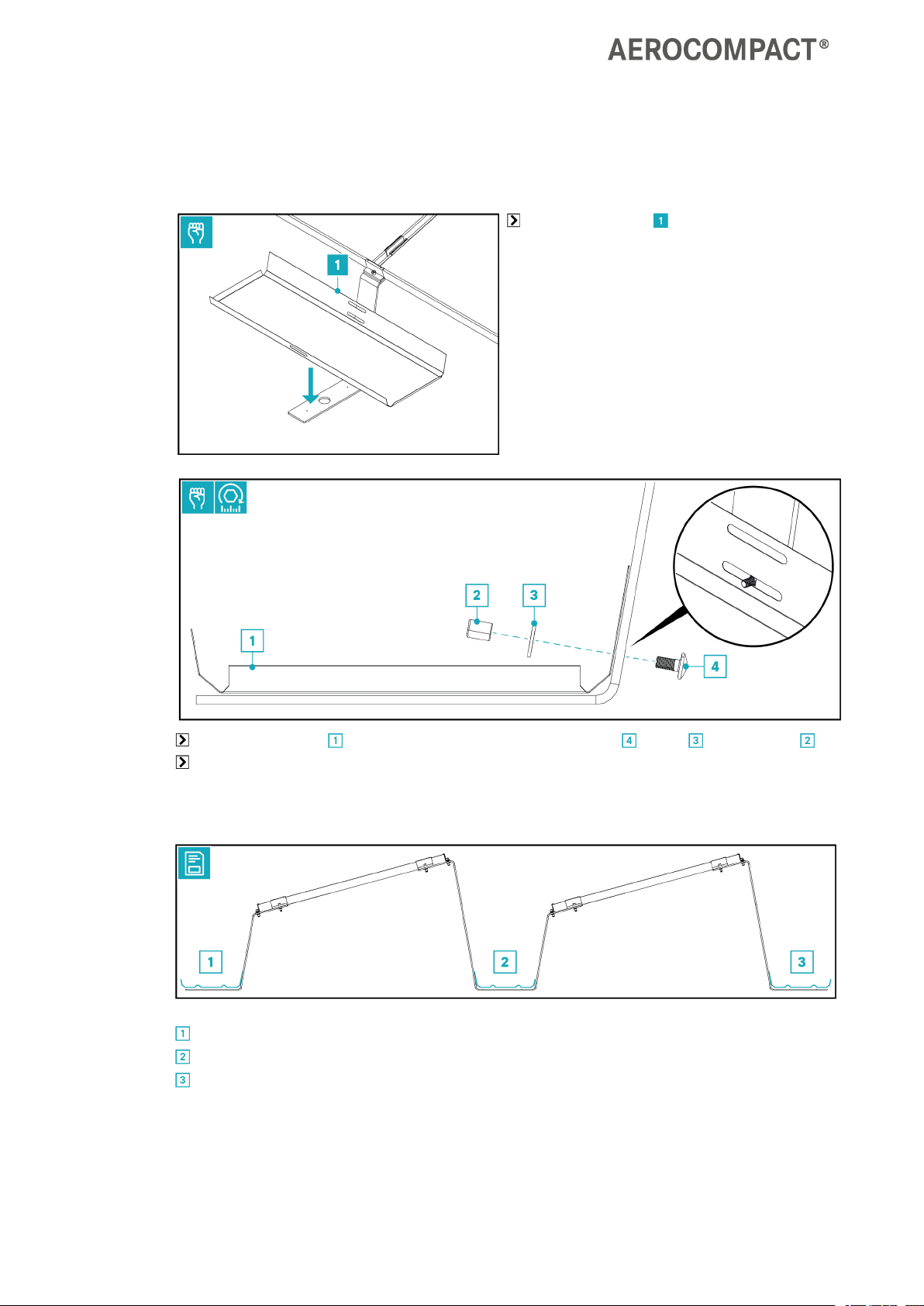
Option 3: Short ballast tray
The short ballast tray can be installed in the following positions:
at the front foot.
on the connector.
at the back foot.
Refer to the Aerotool planning documents for the exact number and position of the short ballast trays.
+
+
+
+
+
+
+
+
+
+
+
+
+
+
+
+
+
+
+
+
+
+
+
+
+
+
+
+
+
+
+
+
+
+
+
+
+
+
+
+
+
+
+
+
+
+
+
+
+
+
+
+
+
+
+
+
+
+
+
+
+
+
+
+
+
+
+
+
+
+
+
+
+
+
+
+
+
+
+
+
+
+
+
+
+
+
+
+
+
+
+
+
+
+
+
+
+
+
+
+
+
+
+
+
+
+
+
+
+
+
+
+
+
+
+
+
+
+
+
+
+
+
+
+
+
+
+
+
+
+
+
+
+
+
+
+
+
+
+
+
+
+
+
+
+
+
+
+
+
+
+
+
+
+
+
+
+
+
+
+
+
+
+
+
+
+
+
+
+
+
+
+
+
+
+
+
+
+
+
+
+
+
+
+
+
+
+
+
+
+
+
+
+
+
+
+
+
+
+
+
+
+
+
+
+
+
+
+
+
+
+
+
+
+
+
+
+
+
+
+
+
+
+
+
+
+
+
+
+
+
+
+
+
+
+
+
+
+
+
+
+
+
+
+
+
+
+
+
+
+
+
+
G15 | G20
Assembly
www.aerocompact.com 20
Installing the short ballast tray
Place the ballast tray centrally on the foot or
connector.
Screw the ballast tray to the foot or connector using the torx screw , washer and socket nut .
Tighten the screws with 15 Nm or 11 ft lb.
Option 4: Long ballast tray
The long ballast tray can be installed in the following positions:
across the front feet.
across the connectors.
across the back feet.
+
+
+
+
+
+
+
+
+
+
+
+
+
+
+
+
+
+
+
+
+
+
+
+
+
+
+
+
+
+
+
+
+
+
+
+
+
+
+
+
+
+
+
+
+
+
+
+
+
+
+
+
+
+
+
+
+
+
+
+
+
+
+
+
+
+
+
+
+
+
+
+
+
+
+
+
+
+
+
+
+
+
+
+
+
+
+
+
+
+
+
+
+
+
+
+
+
+
+
+
+
+
+
+
+
+
+
+
+
+
+
+
+
+
+
+
+
+
+
+
+
+
+
+
+
+
+
+
+
+
+
+
+
+
+
+
+
+
+
+
+
+
+
+
+
+
+
+
+
+
+
+
+
+
+
+
+
+
+
+
+
+
+
+
+
+
+
+
+
+
+
+
+
+
+
+
+
+
+
+
+
+
+
+
+
+
+
+
+
+
+
+
+
+
+
+
+
+
+
+
+
+
+
+
+
+
+
+
+
+
+
+
+
+
+
+
+
+
+
+
+
+
+
+
+
+
+
+
+
+
+
+
+
+
+
+
+
+
+
+
+
+
+
+
+
+
+
+
+
+
+
+
This manual suits for next models
1
Table of contents
Other AEROCOMPACT Inverter manuals


