Aurora PVI-3.0-OUTD-ZZ Manual

EN ENGLISH
IT - ITALIANO
DE DEUTSCH
ES ESPAÑOL
FR FRANÇAIS
CZ ČESKOSLOVENSKÁ
NL NEDERLANDSE
PT PORTUGUÊS
EL ΕΛΛΗΝΕΣ

Photovoltaic Inverters
KEEP THIS DOCUMENT IN A SAFE PLACE
IMPORTANT SAFETY INSTRUCTIONS!
This manual contains important safety instructions that must be followed
during the installation and start-up of the device. It’s recommended to give
special attention to the paragraphs highlighted by the symbol , in order to
reduce the risks of electric shock and prevent damage to the device.
NOTE: This document contains proprietary information of Power-One, Inc. the
contents of this document or any part thereof should not be reproduced or
disclosed to any third party without Power-One’s express written consent.
Photovoltaic Inverters

1 - EN
EN - ENGLISH
Photovoltaic Inverters
Installation and Configuration Manual
for Aurora Photovoltaic Inverters
This document describes the installation and configuration procedure for Power-One Aurora Photovoltaic Inverters.
This document does not replace the User Manual,but is intended to provide a quick installation guide.
If further clarification or other details are required, please see the User Manual on the CD provided within the
product packaging.
The models this document refers to are shown in the table below.
SINGLE PHASE
PVI-3.0-OUTD-ZZ
PVI-3.0-OUTD-S-ZZ
PVI-3.6-OUTD-ZZ
PVI-3.6-OUTD-S-ZZ
PVI-4.2-OUTD-ZZ
PVI-4.2-OUTD-S-ZZ
PVI-5000-OUTD-ZZ
PVI-5000-OUTD-S-ZZ
PVI-6000-OUTD-ZZ
PVI-6000-OUTD-S-ZZ
√
THREE PHASE
PVI-10.0-OUTD-ZZ
PVI-10.0-OUTD-S-ZZ
PVI-10.0-OUTD-FS-ZZ
PVI-12.5-OUTD-ZZ
PVI-12.5-OUTD-S-ZZ
PVI-12.5-OUTD-FS-ZZ
Where ZZ stands for the country code.
For versions with the grounding kit, the user options and modes are described in their application note,
which should be requested directly from Power-One.

2 -EN
INSTALLATION AND CONFIGURATION MANUAL
FOR AURORA PHOTOVOLTAIC INVERTERS
CONTENTS
1Useful information and safety regulations 3
2Package contents inspection 4
3Selection of installation location 5
4Wall mounting 5
5Electrical connections (AC,DC side and PE connection) 7
5.1 AC Side Connections 8
5.2 DC Side Connections 10
6Configuration of input channel operating mode 11
7RS485 communication line connection 13
8Pre-commissioning checks 15
8.1 Electrical checks 15
8.2 Mechanical checks 16
9Start up and connection to the grid 17
10 Possible configurations required at start up 18
11 Start-Up Troubleshooting 19
12 Troubleshooting help 22
System structure 23
Appendices:
A – Pin-Out of RJ12 / RJ45 Connector
B – Cable Wiring Diagram for RS485 Line
C – Technical Data
PVI-3.0/3.6/4.2-OUTD
PVI-5000/6000-OUTD
PVI-10.0/12.5-OUTD

3 - EN
EN - ENGLISH
Photovoltaic Inverters
1. Useful information and safety regulations
This manual contains important safety instructions which must be carefully followed during the installation and
commissioning of the device.It is advisable to pay particular attention to the paragraphs marked with the symbol
, this will reduce the risk of electric shock and prevent damage to the device.
All the operations described below must be carried out exclusively by qualified staff in compliance with national and local
safety regulations.
For all stages of installation, the instructions and warnings shown in the various chapters must be followed step by step
so as to avoid danger situations or the possibility of damaging the equipment.Every operation that does not comply with
these instructions will lead to the immediate loss of the warranty.
There can be live parts, uninsulated parts and hot surfaces while the inverter is working. Unauthorized removal of the
required protections,improper use,faulty installation or inappropriate operation and tampering with the unit (e.g.adding
extra holes) give rise to the risk of serious damage to persons and things and lead to the immediate loss of the warranty.
The system must be connected to the mains distribution system only after the Body appointed to distribute electricity has
given its approval,as required by the national regulations in force.
Check the national regulations and local standards so that the electric installation diagram complies with them.
Always respect the nominal voltage and current data when planning the system (see the technical data table in Appendix
C).

4 -EN
INSTALLATION AND CONFIGURATION MANUAL
FOR AURORA PHOTOVOLTAIC INVERTERS
2. Package contents inspection
Check that the package contents comply with the following list:
PVI-xx-OUTD-yy-zz Inverter [1 piece]
(xx = 3.0/3.6/4.2/5000/6000/10.0/12.5; yy = S /FS; zz = IT/DE/UK/ES/FR/CZ/AU/CN/EL/KR/PT)
Wall mounting bracket [1 piece]
Installation Manual [1 piece]
CD with communication SW and documentation in electronic format [1 piece]
Kit consisting of:
PVI-3.0-OUTD
PVI-3.6-OUTD PVI-4.2-OUTD PVI-6000-OUTD
PVI-5000-OUTD
PVI-10.0-OUTD
PVI-12.5-OUTD
Screws 6.3x70 2 2 3 5
Dowels SX10 2 2 3 5
WAGO flat head angled screwdriver / / 1 /
M20 cable gland 1 1 1 1
M25 cable gland 1 1 / /
M32 cable gland / / 1 /
M40 cable gland / / / 1
M25 cable gland nut 1 1 / /
M32 cable gland nut / / 1 /
M40 cable gland nut / / / 1
Red AWG10 cable with insulated female fastons 1 1 1 /
Black AWG10 cable with insulated female fastons 1 1 1 /
Black AWG12 cable with insulated female fastons / / / 2
36A3M20 type gasket 1 1 1 1
TGM58 cylinder 1 1 1 1
T20 TORX wrench 1 1 1 1
M6x10 screw 1 1 1 /
D.18 washer 3 3 4 5
Perforated screws for front panel lead sealing / / 2 /
Signal terminal board counterparts 2 2 / *
MC4 positive connector counterparts 2 3 4 **
MC4 negative connector counterparts 2 3 4 **
MC positive connector caps (pre-assembled) 2 3 4 **
MC negative connector caps (pre-assembled) 2 3 4 **
*3-way terminal board counterparts (ALARM): 2 pieces; 8-way terminal board counterparts (signals): 2 pieces.
**Per the PVI-10.0/12.5-OUTD-S models:4 pieces;for the PVI-10.0/12.5-OUTD and PVI-10.0/12.5-OUTD-FS models:6 pieces.

5 - EN
EN - ENGLISH
Photovoltaic Inverters
3. Selection of installation location
The installation location for the AURORA must be chosen on the basis of the following considerations:
4.Wall mounting
The AURORA must be mounted vertically; slight inclinations up to a maximum of 5° from vertical are
permitted.Greater inclinations may cause derating of the inverter’s performance with a consequent
reduction in power.
To correctly wall mount the inverter, follow the following procedure:
Note: In the PVI-10.0/12.5-OUTD models the support bracket only permits the upper part of the inverter to be secured through the
procedure previously described; to secure the lower part of the inverter, in the absence of the PEM M6, you must make additional
holes in line with the slot in the inverter’s lower flange (det. [E]), and then use the SX10 dowels and 6.3x70 screws to secure the part
to the wall.
Drill Ø 10 mm holes to a depth of 75 mm in line with the support bracket’s fixing holes (det. [A])
Secure the inverter’s support bracket using the SX10 dowels and 6.3x70 screws provided.The inverter’s spring hook (det.
[B]) must be positioned at the top; the fixing PEM M6 (det. [C]) must be positioned at the bottom.
Hook the inverter to the bracket spring (det. [B]) by the screw holes in the bracket on the back of the inverter (det. [D]).
Secure the lower part of the inverter to the PEM M6 on the bracket (det.[C]) using the M6x10 screw, the D.18 washer and
the slot in the inverter’s lower flange (det. [E]).
Choose a location sheltered from direct sunlight or other sources of heat.
Choose a well ventilated place so as to allow good circulation of air around the unit; avoid places where air
cannot circulate freely around the unit.
Choose a place with sufficient space around the unit to permit easy installation and removal of the object
from the mounting surfaces.
If more than one unit is installed,avoid placing one unit above the other so as to prevent overheating of the unit installed above
through the heat given off by the one below. Some examples of multi-inverter installations are shown in the picture below.
150 mm 150 mm
150 mm 150 mm 150 mm 150 mm150 mm
200 mm
200 mm
200 mm
200 mm
200 mm
150 mm 150 mm 150 mm 150 mm 150 mm 150 mm
Minimum clearances around the unit.

6 -EN
INSTALLATION AND CONFIGURATION MANUAL
FOR AURORA PHOTOVOLTAIC INVERTERS
Inverter wall mounting brackets.
PVI-3.0/3.6/4.2-OUTD PVI-5000/6000-OUTD PVI-10.0/12.5-OUTD
Rear of the inverter.
PVI-3.0/3.6/4.2/5000/6000-OUTD PVI-10.0/12.5-OUTD

7 - EN
EN - ENGLISH
Photovoltaic Inverters
5. Electrical connections (AC,DC side and PE connection)
Warning! Power One Aurora inverters are TRANSFORMERLESS inverters. This topology means the photovoltaic generator
must be kept floating to earth: no generator pole should be earthed.
• Use of Power One transformerless inverters with photovoltaic modules that require the generator’s negative pole to
be earthed is allowed in compliance with the instructions provided for by the solution with grounding kit which are
described in its application note and provide for the use of an external isolation transformer.For further details request
the related application note from Power One or consult the website www.power-one.com.
• Use of Power One transformerless inverters with photovoltaic modules that require the generator’s positive pole to
be earthed is not allowed.
• Use of Power One transformerless inverters with photovoltaic modules that have high earthing capacity (typically
modules stuck onto metal plate) is allowed within the limits provided for by the instructions which are described in
the related application note and provide for each single inverter to be uncoupled by means of an external isolation
transformer. For further details request the related application note from Power One or consult the website www.
power-one.com.
Warning! Power One Aurora inverters must be connected to earth (PE) by the prepared clamp and using a cable with a
section suitable for the maximum failure current that can be had on the system. Any failure of an inverter which is not
connected to earth by the appropriate terminal block or screws is to be considered outside the warranty.
Warning! Power One Aurora inverters are equipped with an internal protection system capable of detecting dispersion
currents to earth on the DC side of the system or inside the inverter after the AC connection terminal block.These protections
are in place so as to disconnect the inverter in the event of accidental direct contact or loss of insulation but are nevertheless
not capable of protecting the inverter from a dead earth short of one of the photovoltaic generator’s poles when the
equipment is already connected to the AC grid. This event could damage the inverter and any failure is to be considered
outside the warranty.
Warning! Power One Aurora inverters cannot be powered by unlimited sources of current, e.g. batteries. Powering the
device with this type of energy source can cause irreparable damage to the unit,with consequent invalidity of the warranty
conditions.
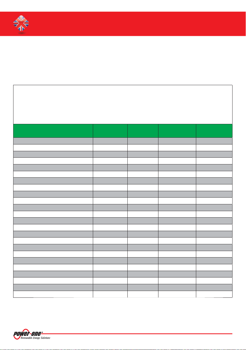
Warning! For the AC and DC side use cables with a suitable section for the internal conductor (refer to Appendix C).

8 -EN
INSTALLATION AND CONFIGURATION MANUAL
FOR AURORA PHOTOVOLTAIC INVERTERS
Remove the inverter’s front panel by
unscrewing the screws on the panel with
the Torx T20 wrench provided
Warning! For connection to the grid an automatic circuit breaker with adequate differential protection can be used
optionally.For the choice of device,refer to the table below:
Characteristics
Automatic
Circuit Breaker
INVERTER MODEL
PVI-3.0-OUTD PVI-3.6-OUTD PVI-4.2-OUTD PVI-5000-OUTD PVI-6000-OUTD PVI-10.0-OUTD PVI-12.5-OUTD
Type
AUTOMATIC CIRCUIT BREAKER WITH MAGNOTHERMIC-DIFFERENTIAL PROTECTION
Rated Voltage
230Vac 400Vac
Rated Current
20 20 25 32 40 20 25
Magnetic Protection Characteristics
B/C
Differential Protection Type
A/AC
Differential Sensitivity
300mA
Number of Poles
2 3/4
5.1 AC SIDE CONNECTIONS
Make sure the AC line is disconnected.
Place the M25/M32/M40 cable gland in the hole used for the AC cables and pass the cable through for connection to the
AC mains and PE connection.Use the following types of cable:
• Single-phase inverter: three-pole cable (L+N+PE)
• Three-phase inverter with triangular connection to the grid: four-pole cable (R+S+T+PE)
• Three-phase inverter with star connection to the grid: five-pole cable (R+S+T+N+PE)
The table below shows the locking ranges for the cable glands provided with the inverters.
If the green-yellow protection cable is separate to the mains connection cable, use one of the holes present and the
related M20 cable gland supplied.
Make sure that the cable selected for the connection has an external diameter that fits the cable gland through which it
must be inserted to the inside the inverter.
Connect the cables respecting the position of the earth lead (PE).In the PVI-3.0/3.6/4.2/5000/6000-OUTD models it is also possible
to connect the earth lead to the fastening screw on the board by means of an eyelet or spade lug cable terminal (det.[F]).
Front panel:
panel removal screws.
Cable Gland Locking Range
M20 7 – 13 mm
M25 10 – 17 mm
M32 13 – 21 mm
M40 19 – 28 mm
√

9 - EN
EN - ENGLISH
Photovoltaic Inverters
AC TERMINAL BLOCK
PVI-3.0/3.6/4.2-OUTD PVI-5000/6000-OUTD PVI-10.0/12.5-OUTD
[G]
[F] [F]
Note: In the PVI-5000/6000 models, a WAGO screwdriver allowing the
terminal block’s contacts to be opened is provided in the special kit.
The procedure for opening the contacts and tightening cables is as
follows:
1) Insert the screwdriver in slot with the screwdriver facing downwards.
(det. [W])
2) Lightly press the screwdriver from the top to the bottom.
3) Insert the screwdriver until the clamp opens.
4) Insert the cable in the clamp.
5) Remove the screwdriver.
Note: In models PVI-3.0/3.6/4.2/10.0/12.5-OUTD-IT and models PVI-
10.0/12.5-OUTD-CN there is a metal turret (det. [G]) which, by means of
the special bracket and perforated screw (det.[H]), allows the contacts to
be closed with the related lead sealing.
Note: In the PVI-10.0/12.5-OUTD-IT models ONLY,connection of the neutral (N)
lead is optional,depending on the system where the inverter is installed.If the LV
grid connection is three-phase + N (star configuration),the N lead must also be
connected to ensure the phases are balanced correctly against it.On the other
hand,if the grid connection does not have neutral (triangle configuration), e.g.
in a system producing energy alone,this connection can be omitted;in this case
the“3ph MOD” switch must be set on the symbol Δ(det.[I])
This switch is not available on other models and only the star
configuration can be used (there is a jumper that binds operation to
a grid with neutral).
Tighten the cable gland making sure that it grips the surface of the cable so that the seal is ensured and hence the level of
environmental protection. It is possible to use one of the holes on the inverter for the passage of the green-yellow cable:
in this case remove the screw cap and use the M20 cable gland for the cable’s passage.
[W]
[H]
[I]

10 -EN
INSTALLATION AND CONFIGURATION MANUAL
FOR AURORA PHOTOVOLTAIC INVERTERS
5.2 DC SIDE CONNECTIONS
Check the polarity of each couple of cables that must be connected to the inverter input:mark the cable corresponding to
the positive pole so as to be able to distinguish it from the one corresponding to the negative pole. In the case of several
strings,observe the correspondence between the negative and positive of each string.
Check the polarity value (empty) of each couple of cables that must be connected to the inverter input: in no case should
the value exceed the maximum input voltage limit.
Voltage values above the specifications can irreparably damage the unit.Any consequent failure of the inverter is
to be considered outside the warranty.
In the case of –FS models the input current in each connector must not exceed 10A (internal fuse current limit). Higher
values can damage the fuse.For all the other models the input current limit is 20A for each connector.
Crimp the MC4 counterparts to the string cables or the cables from the string disconnecting switches (external) paying
attention to the polarity of the voltage and the connector / terminal.
Make sure the built-in disconnecting switch ( –S and –FS versions) is on the OFF position or the external disconnecting
switches are open.
Connect the previously crimped connectors to the input connectors on the lower part of the inverter, respecting the polarity.
POLARITY CONNECTOR TERMINAL
Positive
Negative
Lower part of PVI-4.2-OUTD(-S)
Lower part of PVI-10.0/12.5-OUTD(-FS)
Lower part of PVI-3.0/3.6-OUTD(-S)
Lower part of PVI-5000/6000-OUTD

11 - EN
EN - ENGLISH
Photovoltaic Inverters
6. Configuration of input channel operating mode
The two input channels can be configured in two modes: independent mode and parallel mode.
The choice of input channel configuration depends on the photovoltaic generator’s characteristics and the inverter’s
power and current limits.Refer to the system design documentation,or the documentation on the CD,for the inverter
input configuration choice.
Warning! Forthe twochannelstobeusedinindependentmode,it is a NECESSARY conditionthatthephotovoltaic generator
connected to each input has a maximum current and power below the channel’s current and power limit.
Warning! For the two channels to be used in parallel mode,it is RECOMMENDED that the photovoltaic generator connected
to the two inputs has strings with the same number of modules in series and that all the modules have the same installation
conditions (inclination / orientation).
Refer to the technical data table in Appendix C to find out the current and power limits of each input channel for the
various inverter models.
If the string’s current or power is above the current or power limit of the input channel to which it is connected, the
two input channels MUST be configured in parallel. This condition also concerns the case where the photovoltaic
generator comprises only one string with power above the inverter’s single input channel power limit.
Note:
If the conditions shown above are not met, consult the photovoltaic system’s designer immediately.
√

12 -EN
INSTALLATION AND CONFIGURATION MANUAL
FOR AURORA PHOTOVOLTAIC INVERTERS
CONFIGURATION MODES FOR THE CHANNELS IN PARALLEL
Should it be necessary to configure the channels in parallel, follow the following procedure:
Remove the front panel of the inverter
Using the AWG10/12 cables with insulated female fastons,connect the positive terminal of input 1 to a positive terminal
of input 2 (det. [L]). Repeat the connection for the negative terminals (det.[M]).
Act on the dip-switch identified by the INPUT MODE printing and put in on the PAR position (det. [N]).
Connection in parallel of the input channels.
Configuration dip-switch for input channel operation mode.
PVI-3.0/3.6/4.2-OUTD
[L]
[M]
PVI-5000/6000-OUTD
[L]
[M]
PVI-10.0/12.5-OUTD
[M] [L]
PVI-3.0/3.6/4.2-OUTD
[N]
PVI-5000/6000-OUTD
[N]
PVI-10.0/12.5-OUTD
[N]

13 - EN
EN - ENGLISH
Photovoltaic Inverters
Configuration dip-switch for input channel operation mode.
The RS485 communication port is the inverter’s communication port. AURORA uses a HALF-DUPLEX RS485 communication line made up of two
transmission reception lines (+T/R and –T/R) and a reference communication line (RTN): all three lines must be wired in a daisy-chain (“in-out”).
It is advisable to use a twisted-pair screened cable for the communication line: the screen must be earthed at only one point (typically near the
monitoring system) and continuity inside each element of the chain must be given to the screen. Refer to Appendix B.
The chain connection can be made without distinction by using the connector couples (one for in and one for out – det. [P]) or the terminal
block (det. [Q] or det. [R]).The connectors are identified by the printing“RS485(A)” and “RS485(B)”: use of connector“A” as in and “B” as out is not
compulsory (both connectors can be used as in or out). Refer to APPENDIX A for the PIN-OUT of the RJ12 and RJ45 connectors.
The last inverter in the daisy chain must be “terminated” or the 120 Ohm communication line termination resistance must be activated by
switching the dip-switch (det.[S]).
The PVI-3.0/3.6/4.2/10.0/12.5-OUTD models are equipped with a two-level terminal block allowing one level to be used for line-in connection
and the other for line-out connection.The terminal block is also equipped with the LNK terminal for the PVI-3.0/3.6/4.2-OUTD models and SCLD
for the PVI-10.0/12.5-OUTD models allowing continuity to be given to the cable screen.
On the other hand the PVI-5000/6000-OUTD models are equipped with a one-way terminal block (det.[Q]) and therefore it is necessary to couple
the line-in and line-out leads in the same clamp.
Note about the built-in USB port in the PVI-3.0/3.6/4.2/5000/6000-OUTD models
The USB communication port is a service port.This port exists for diagnostic use and the internal controller’s firmware upgrade and is limited to service
staff. Although drivers have been released (compatible with Windows XP and for which no upgrades are envisaged) which permit this port to be also
used for monitoring (not recommended),the primary use remains strictly tied to debugging and updating the system. Power-One recommends the use
of the RS485 port for the continuous monitoring of system data.
With regard to the communication interface, the use of the dedicated Power-One PVI-RS485_RS232 or PVI-USB-RS485_232 type converter
is strongly recommended in order to prevent compatibility problems that can sometimes be encountered with the standard models on the
market.
RJ12 connectors,
terminal block and termination
resistance for the PVI-3.0/3.6/4.2-OUTD
RJ45 connectors, terminal block and
termination resistance for the
PVI-5000/6000-OUTD
RJ45 connectors,
terminal block and termination
resistance for the PVI-10.0/12.5-OUTD
[S] [S] [S]
[R] [Q] [R]
[P] [P] [P]

14 -EN
INSTALLATION AND CONFIGURATION MANUAL
FOR AURORA PHOTOVOLTAIC INVERTERS
Anyway, in order to make the power limitation mechanism possible as required by the directive in force, further wiring of the inverters is
required and this can be carried out in two modes:
This way when several inverters are connected according to one of the diagrams as of above and one unit goes off / fails, a power output
limitation of 4600W is automatically set in all the units thus preventing a power imbalance between the phases.
Note about the use of the “Alarm” terminal block: the alarm terminal block makes the contacts of a relay available to indicate configurable
alarm conditions (for information on the possibility and configuration modes of the“Alarm” function, see the user manual on the CD that comes in the
package). The alarm contact is available under normally open (N.O.) or normally closed (N.C.) operation compared to the common terminal (C). The
maximum rating for voltage / current that the relay can support is 230V / 1A.
“Alarm”terminal block in
PVI-3.0/3.6/4.2-OUTD “Alarm”terminal block in
PVI-5000/6000-OUTD “Alarm”terminal block in
PVI-10.0/12.5-OUTD
Functional diagram
for the alarm contact
Note: The VDEW directive (envisaged in Germany) provides that a maximum imbalance of 4600W
for the phases is tolerated in a three-phase system. In the PVI-6000-OUTD-DE models, which have a
rated output power above this limit, the “Alarm” and “Remote” contacts will have a jumper fitted in the
factory.
RS485A RS485B RS485A RS485BRS485A RS485B
Wiring through the terminal blocks
Wiring through the RJ45 connectors

15 - EN
EN - ENGLISH
Photovoltaic Inverters
8. Pre-commissioning checks
Warning! Carrying out preliminary checks before commissioning the inverter is always recommended; this way you avoid
possible damage to the unit that could be caused by its faulty installation.
The main checks to carry out are the following:
8.1 ELECTRICAL CHECKS
PE connection check: check the inverter has an earth connection.
Warning! Power One Aurora inverters must be connected to earth by the prepared clamp and using a cable with a section
suitable for the maximum failure current that can be had on the system.Any failure of an inverter which is not connected
to earth by the appropriate terminal block or fastening screws is to be considered outside the warranty.
Check of the input voltage values: check that the inverter’s input voltage does not exceed the permitted limits (ref.
technical data table in Appendix C). Voltage values above the specifications can irreparably damage the unit. Any
consequent failure of the inverter is to be considered outside the warranty.
Check of the input voltage polarity: make sure the input voltage has the correct polarity.
Check of the photovoltaic generator’s insulation to earth: use an insulation tester to make sure that insulation resistance
to earth for the DC section of the system is greater than 1MOhm. Resistance insulation values of less than 1MOhm do
not permit the inverter to complete the parallel with the grid.Resistance insulation values of less than 10MOhm can hide
insulation problems that could be accentuated in periods when there is humidity in the photovoltaic generator.For more
information refer to the user manual on the CD that comes in the package.
Warning! Power One Aurora inverters are equipped with an internal protection system capable of detecting dispersion
currents to earth on the DC side of the system or inside the inverter after the AC connection terminal block. These
protections, in place so as to disconnect the inverter in the event of accidental direct contact or loss of insulation, are
nevertheless not capable of protecting the inverter from a dead earth short of one of the photovoltaic generator’s poles
when the equipment is already connected to the AC grid. This event could damage the inverter and any failure is to be
considered outside the warranty.
Check of the grid voltage: check that the voltage of the grid to which the inverter will be connected complies with the
values shown in the technical data table in Appendix C.
Voltage values above the specifications can irreparably damage the unit.

16 -EN
INSTALLATION AND CONFIGURATION MANUAL
FOR AURORA PHOTOVOLTAIC INVERTERS
8.2 MECHANICAL CHECKS
Make sure the cable glands are mounted properly. The cable glands must be adequately locked and prevent any
movement of the cable. Also make sure the cable glands are solidly fixed to the inverter’s chassis.
Make sure that the gasket on the front panel has been correctly mounted.The gasket must completely cover the red line
on the front of the inverter.
Fasten the inverter’s front panel by screwing the screws on the panel with the Torx T20 wrench provided.
Warning! To ensure the inverter is waterproof, the front panel screws must be tightened to a torque wrench setting of at
least 1.5 Nm (13.2 in-lbs).
Reference Line Correct Mounting
Incorrect Mounting

17 - EN
EN - ENGLISH
Photovoltaic Inverters
9. Start up and connection to the grid
Once the pre-commissioning checks have been performed,it is possible to proceed to starting up the inverter and connecting
it to the grid, following the procedure shown below.
N
ote: the inverter is powered ONLY by the voltage coming from the photovoltaic generator: presence of grid voltage alone IS NOT
SUFFICIENT to permit the inverter to start up.
Note: the inverter start-up voltage (Vstart) is the input voltage value though which the inverter connects to the grid. This
value avoids repeated connection and disconnection in periods of reduced radiation (typically in the morning). It is possible
to modify the start-up voltage within a set range via the display and the four keys (Ref. Par. 10 and the technical data table in
Appendix C).
Nevertheless, it is advisable to reduce the start-up voltage only when really necessary or when modification of the parameter
is required by the configurer; this is to avoid repeated connection and disconnection to the grid which could lead to stress on
the parallel grid electromagnetic devices (relays).For more information in this respect refer to the user manual on the CD that
comes in the package.
Note: the start-up voltage also sets the minimum voltage for the inverter to operate in MPPT.The inverter turns itself off because of
input undervoltage when the input voltage (for each channel) drops below 70% of the start-up voltage (for the channel). For more
information in this respect refer to the user manual on the CD that comes in the package.
Note: during the grid voltage check and measurement of the insulation resistance,the values for the grid voltage and frequency and
the insulation resistance measured by the inverter are shown on the display.The inverter completes parallel with the grid SOLELY if the
grid parameters meet the ranges provided for by the regulations in force and if the insulation resistance is greater than 1Mohm.
Note: during the night, or more generally when the input voltage (DC) is insufficient to turn on the internal auxiliary power supply,
the inverter will be completely off.
Put the built-in disconnecting switch (versions –S and –FS) to the ON position or close the external disconnecting
switches: if the input voltage applied to one of the two input channels is greater than the minimum default voltage, the
inverter will light up showing the“Initializing...please wait”message on the display.
Depending on the input voltage value,the inverter will show various messages on the display and change the behaviour
of the three LED:
If the preliminary checks for parallel to the grid are successful, the inverter connects to the grid and begins to export power to the
grid.At this stage, the display shows the inverter’s parameters in cycles.The green LED stays lit whereas the others are off.
Turning off the unit: follow the operations described for commissioning in reverse order. Opening the switch downstream the
inverter will light up the yellow LED and display message W003 and then“No Vac”; opening the built-in disconnection switch or
the external disconnection switches will completely turn off the unit (LED off and display off).
Input voltage Display message LED status Description
Vin<Vstart Waiting sun
Green=FLASHING
Yellow=OFF
Red=OFF
The input voltage is not sufficient to permit
connection to the grid.
Vin>Vstart No Vac
Green=FLASHING
Yellow=ON
Red=OFF
There is sufficient input voltage to permit
connection to the grid:the inverter waits until there
is grid voltage to carry out the parallel.
With the inverter in“No Vac”status,close the AC switch downstream the inverter so as to apply the grid voltage to the inverter:the inverter
performs the grid voltage check, measures the photovoltaic field’s insulation resistance against earth and carries out other self-diagnosis
checks.During the checks before the parallel with the grid,the green LED keeps flashing,the others are off.

18 -EN
INSTALLATION AND CONFIGURATION MANUAL
FOR AURORA PHOTOVOLTAIC INVERTERS
10. Possible configurations required at start up
Below is a list of possible configurations that may be required at the inverter’s start-up.Other configurations are
possible,these are not strictly related to the inverter’s start-up and for them you should refer to the User Manual.
The following configurations can be modified with the four keys on the display (Esc, Up, Down and Enter); by
pressing the Up and Down keys you go from one item to another or scroll the numerical scale, by pressing the
Esc key you return to the previous menu and by pressing the Enter key you go to the sub-menu corresponding
to the selected item or you go to the next figure to modify. To access the following functions, you have to open
the“Settings”item from the main menu,entering the password which is 0000 by default.
Configuration of the RS458 port address (Address):When there are several inverters wired on the same RS485 line (ref.
Par. 7), the RS485 port address must be different for each inverter (N.B.“Auto” is not permitted as an address); to modify
the address you have to access the Address sub-menu.
Date/Time Settings (Time): On first start-up of the inverter, it is necessary to configure the date and time by accessing
the Time sub-menu.
Language settings (Language): Should it be necessary, you can choose between the national language and English by
accessing the language sub-menu.
Start-up voltage (Vstart): The start-up voltage can be regulated by accessing the Vstart sub-menu and, in the case of
independent channel configuration,it is possible to configure the Vstart for channel 1 and channel 2 separately.
Autotest function for interface protection (Autotest): The Autotest function is only on -IT models and allows the
interface protection to be tested for grid OverVoltage, UnderVoltage, OverFrequency and UnderFrequency. When the
inverter carries out the Autotest, it varies the protection thresholds until the value at which the inverter is operating
is reached and when it exceeds this value and if the protection is sufficient, the inverter disconnects itself within a
certain time which is set by the local standard.The test result is shown on the display with an indication of the value and
the intervention time for the protection. To access this function you must open the Autotest sub-menu, selecting the
protection to be tested (OV, UV, OF, UF).
This manual suits for next models
15
Table of contents
Languages:
Other Aurora Inverter manuals