1.0 INTRODUCTION
The E3MINI Series central emergency lighting inverter system integrates the latest
inverter and microprocessor technology to produce a pure sine-wave power output.
With typical 3% or less steady state losses, it makes it ideal for energy saving and green
initiatives. It is designed specifically for emergency lighting and meets the needs of all
lighting loads with its pure sine-wave output which is the ONLY method of power that
will ensure any lighting load type will be powered safely, efficiently and effectively. The
E3MINI Series meets the Emergency Lighting Backup requirements that demand high
efficiency, versatility, load compatibility, energy savings, high performance, and high
quality.
1.1 Mechanical Design Features
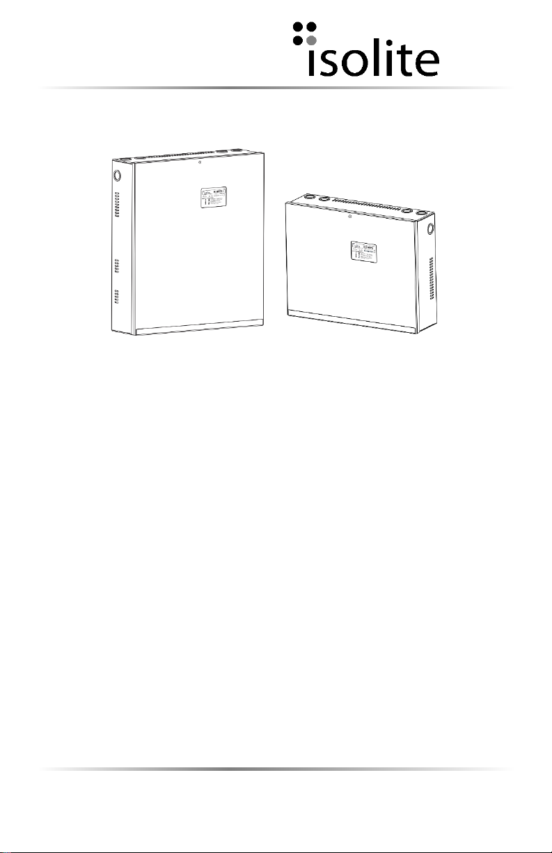
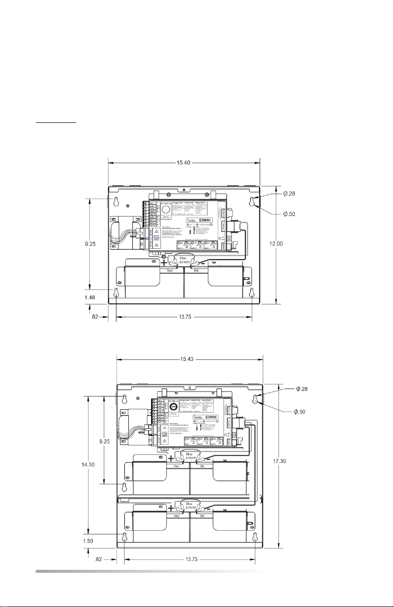
Batteries and electronics are contained in a single cabinet which makes installation
very easy. Wall mounting can be achieved with 4 mounting holes capable of accepting
¼” lag-bolts and electrical knock outs (EKO’s) are available on three surfaces. Quick
access to the interior of the cabinet for battery inspection and maintenance is
accomplished by the removal of a single screw which holds the front cover. A single
module containing all electronics can be easily removed for upgrade or replacement.
This single module makes maintenance and repair easier and more cost effective
because specialized training is not required.
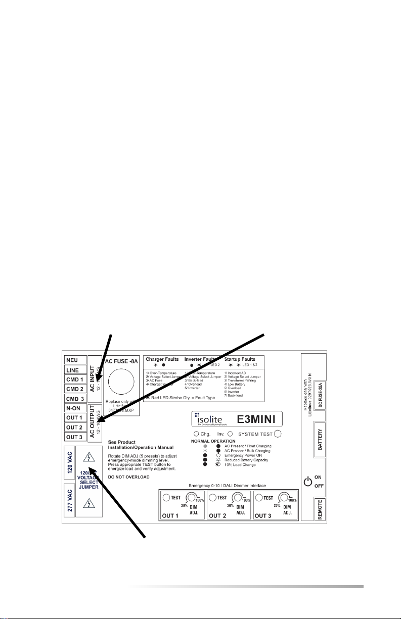
1.2 Electrical Design Features
Through the use of Pulse Width Modulation (PWM) and the latest MOSFET
technology, E3MINI Series can produce a pure sine-wave output which is compatible
with all types of lighting loads. User selectable Input and Output voltage of either 120
VAC or 277 VAC makes for versatility with Electrical Contractors and field installations. A
high crest factor of up to 10X (125W model) is extremely beneficial for high-inrush loads
and also ideal for bringing Normally-Off lighting loads on from a cold start. This high
crest factor also improves the dynamic response so mixing Normally-On and Normally-
Off loads together causes less performance loss than traditional inverters. Since the
active PWM regulation scheme produces a very low THD waveform, the E3MINI Series
can power up even the most demanding loads driving its output with power factor
capabilities ranging from 0.5 leading to 0.5 lagging.
Adding to the versatility are the multiple output types of Normally-On and the
multipurpose Normally-Off/Switched outputs. These outputs are capable of switching
the emergency lighting loads on and off making energy savings and green initiatives
easy to accomplish and all outputs are capable of producing full output power and have
no derating. The batteries are charged by a temperature compensated charger
integrated into a bi-directional converter. A three rate charging scheme and bi-
directional converter topology ensures maximum float life and minimal ripple current on
the batteries.