AEROCOMPACT CompactGROUND GS15 User manual

CompactGROUND
GS15
Assembly Instructions
Version: 01
Language: English | Original language: German
Original installation instructions
Important! Read carefully before installation!

GS15
www.aerocompact.com 2
Legal Notice
Subject to changes due to technical improvements. These assembly instructions correspond to the technical
status of the delivered product and not to the current development status at the manufacturer.
If pages or parts of the assembly instructions are missing, please contact the manufacturer's address given
below.
The original language of these assembly instructions is German. Any assembly instructions in another lan-
guage are a translation of the assembly instructions in German.
The assembly instructions are protected by copyright. Without written permission from AEROCOMPACT®
the assembly instructions may not be copied, reproduced, microfilmed, translated or converted for storage
and processing in computer systems, either in part or in full.
Copyright by © AEROCOMPACT®
Manufacturer
AEROCOMPACT® Holding
Sonnenstraße 10
A 6822 Satteins | Austria
office@aerocompact.com
www.aerocompact.com
Update
This manual is subject to change without notice. This does not represent any obligation on the part of the
manufacturer.
Creation date
08/2022
+
+
+
+
+
+
+
+
+
+
+
+
+
+
+
+
+
+
+
+
+
+
+
+
+
+
+
+
+
+
+
+
+
+
+
+
+
+
+
+
+
+
+
+
+
+
+
+
+
+
+
+
+
+
+
+
+
+
+
+
+
+
+
+
+
+
+
+
+
+
+
+
+
+
+
+
+
+
+
+
+
+
+
+
+
+
+
+
+
+
+
+
+
+
+
+
+
+
+
+
+
+
+
+
+
+
+
+
+
+
+
+
+
+
+
+
+
+
+
+
+
+
+
+
+
+
+
+
+
+
+
+
+
+
+
+
+
+
+
+
+
+
+
+
+
+
+
+
+
+
+
+
+
+
+
+
+
+
+
+
+
+
+
+
+
+
+
+
+
+
+
+
+
+
+
+
+
+
+
+
+
+
+
+
+
+
+
+
+
+
+
+
+
+
+
+
+
+
+
+
+
+
+
+
+
+
+
+
+
+
+
+
+
+
+
+
+
+
+
+
+
+
+
+
+
+
+
+
+
+
+
+
+
+
+
+
+
+
+
+
+
+
+
+
+
+
+
+
+
+
+
+

GS15
www.aerocompact.com 3
TOC
About This Document 5
Applicable Documents 5
Explanation of Symbols 5
Symbols in Illustrations 5
Target group 6
Appropriate use 6
Liability, Warranty, Guarantee 6
Guarantee 7
General information on liability 7
Systems with clamping on the short side of the module 7
Systems with roof protection pads 7
Safety 9
Requirements of personnel 9
Working safely 9
Breakthrough protection 9
Climbing aids 9
Weather conditions 9
Dangers from the environment 9
Protection against falling objects 10
Personal protective equipment (PPE) 10
System Overview 11
Basic components GS15 11
Ballasting 12
Accessories 12
Accessories for grounding / potential equalization (USA) 12
Variants 14
Assembly 15
Attach roof protection pad (optional) 15
Pre-install the clamps 16
Measure area, place brackets and connector brackets 17
Installing the modules 18
Place ballast 20
Version 1: Ballasting directly on the brackets or connector brackets 20
Version 2: Short ballast trays 20
Version 3: Long ballast tray 21
Install cable pipe assembly (optional) 22
Mount cable pipe to ballast tray 22
Fasten cable pipes with brackets 23
Grounding 24
Install grounding / bonding equipment (not USA-compliant) 24
Installing grounding (USA-compliant) 25
Maintenance 27
Complete System 27
Fittings 27
Dismantling 28
+
+
+
+
+
+
+
+
+
+
+
+
+
+
+
+
+
+
+
+
+
+
+
+
+
+
+
+
+
+
+
+
+
+
+
+
+
+
+
+
+
+
+
+
+
+
+
+
+
+
+
+
+
+
+
+
+
+
+
+
+
+
+
+
+
+
+
+
+
+
+
+
+
+
+
+
+
+
+
+
+
+
+
+
+
+
+
+
+
+
+
+
+
+
+
+
+
+
+
+
+
+
+
+
+
+
+
+
+
+
+
+
+
+
+
+
+
+
+
+
+
+
+
+
+
+
+
+
+
+
+
+
+
+
+
+
+
+
+
+
+
+
+
+
+
+
+
+
+
+
+
+
+
+
+
+
+
+
+
+
+
+
+
+
+
+
+
+
+
+
+
+
+
+
+
+
+
+
+
+
+
+
+
+
+
+
+
+
+
+
+
+
+
+
+
+
+
+
+
+
+
+
+
+
+
+
+
+
+
+
+
+
+
+
+
+
+
+
+
+
+
+
+
+
+
+
+
+
+
+
+
+
+
+
+
+
+
+
+
+
+
+
+
+
+
+
+
+
+
+
+
+

GS15
www.aerocompact.com 4
Disassemble components 28
Dismantle clamps 28
+
+
+
+
+
+
+
+
+
+
+
+
+
+
+
+
+
+
+
+
+
+
+
+
+
+
+
+
+
+
+
+
+
+
+
+
+
+
+
+
+
+
+
+
+
+
+
+
+
+
+
+
+
+
+
+
+
+
+
+
+
+
+
+
+
+
+
+
+
+
+
+
+
+
+
+
+
+
+
+
+
+
+
+
+
+
+
+
+
+
+
+
+
+
+
+
+
+
+
+
+
+
+
+
+
+
+
+
+
+
+
+
+
+
+
+
+
+
+
+
+
+
+
+
+
+
+
+
+
+
+
+
+
+
+
+
+
+
+
+
+
+
+
+
+
+
+
+
+
+
+
+
+
+
+
+
+
+
+
+
+
+
+
+
+
+
+
+
+
+
+
+
+
+
+
+
+
+
+
+
+
+
+
+
+
+
+
+
+
+
+
+
+
+
+
+
+
+
+
+
+
+
+
+
+
+
+
+
+
+
+
+
+
+
+
+
+
+
+
+
+
+
+
+
+
+
+
+
+
+
+
+
+
+
+
+
+
+
+
+
+
+
+
+
+
+
+
+
+
+
+
+

GS15
About This Document
www.aerocompact.com 5
ABOUT THIS DOCUMENT
These installation instructions describe the procedure for installing the product. Read these assembly instruc-
tions carefully before starting the assembly. Follow the instructions carefully to ensure correct installation of
the product.
Applicable Documents
The following documents are a part of these installation instructions and are absolutely necessary for the
correct assembly of the system:
oProject report from AEROTOOL
oPlanning documents and drawings
Explanation of Symbols
In order to make these assembly instructions easy to understand, uniform safety instructions, symbols, terms
and abbreviations are used. The following symbols indicate notes which are not relevant to safety, but
which make working with the assembly instructions easier.
Requirements for an action are depicted with this symbol. Make sure that all requirements are met before
you carry out the following actions.
Action steps are depicted with this symbol. Carry out the steps in the specified order.
The result of the action is depicted with this symbol.
This note provides useful information for a smooth assembly of the product.
Symbols in Illustrations
Activities
Certain activities are required to carry out the assembly. These activities are shown in the illustrations with
the following symbols.
Check AEROTOOL planning documents Visual inspection
Activity by hand Observe right angle
Optional component,
optional installation method
+
+
+
+
+
+
+
+
+
+
+
+
+
+
+
+
+
+
+
+
+
+
+
+
+
+
+
+
+
+
+
+
+
+
+
+
+
+
+
+
+
+
+
+
+
+
+
+
+
+
+
+
+
+
+
+
+
+
+
+
+
+
+
+
+
+
+
+
+
+
+
+
+
+
+
+
+
+
+
+
+
+
+
+
+
+
+
+
+
+
+
+
+
+
+
+
+
+
+
+
+
+
+
+
+
+
+
+
+
+
+
+
+
+
+
+
+
+
+
+
+
+
+
+
+
+
+
+
+
+
+
+
+
+
+
+
+
+
+
+
+
+
+
+
+
+
+
+
+
+
+
+
+
+
+
+
+
+
+
+
+
+
+
+
+
+
+
+
+
+
+
+
+
+
+
+
+
+
+
+
+
+
+
+
+
+
+
+
+
+
+
+
+
+
+
+
+
+
+
+
+
+
+
+
+
+
+
+
+
+
+
+
+
+
+
+
+
+
+
+
+
+
+
+
+
+
+
+
+
+
+
+
+
+
+
+
+
+
+
+
+
+
+
+
+
+
+
+
+
+
+
+
GS15
About This Document
www.aerocompact.com 6
Tools
Certain tools are required to carry out the assembly. These tools are shown in the illustrations with the fol-
lowing symbols.
Measuring tape, measure Cordless screwdriver, screwdriver
Pencil, mark Torque wrench,
Observe torque
Chalk line Drilling machine, drill
Scissors, tin snips, cut to size
Target group
These installation instructions are intended for trained personnel who are familiar with the installation of
photovoltaic systems. The personnel should also be familiar with working on roofs and know the local reg-
ulations regarding work safety. The personnel must also observe the instructions in the Safety chapter.
Appropriate use
The CompactGROUND GS ground-mounted system is designed for installing PV modules on flat roofs. The
inclination may be max. 5° (ballasting with ballast stones). A project specific clarification is required for a
inclination of more than 5°. The system must be properly installed in accordance with these installation
instructions and the planning documents supplied.
PV modules used with the CompactGROUND GS system should be approved by the module manufacturer.
AEROCOMPACT accepts no liability for loss of performance or damage of any kind to the PV modules.
Any other use of the CompactGROUND GS system is considered improper.
Liability, Warranty, Guarantee
These assembly instructions and the project report supplied with the product are integral parts of the
product. The information, data and instructions given in the assembly instructions were up to date at the
time of printing. No claims can be made for products already delivered that deviate from the information,
illustrations and descriptions.
The project report supplied with the system contains the static/ structural calculation related to the location.
Follow the position of the modules on the roof, the number and position of the building protection pads
and the ballast distribution exactly according to the project report. If the module layout on the roof changes
due to local conditions, e.g. unforeseen interference areas, the structural analysis must be recalculated. The
Aerocompact system is designed and planned using the AEROTOOL software.
Aerocompact accepts no liability for damage and malfunctions caused by:
+
+
+
+
+
+
+
+
+
+
+
+
+
+
+
+
+
+
+
+
+
+
+
+
+
+
+
+
+
+
+
+
+
+
+
+
+
+
+
+
+
+
+
+
+
+
+
+
+
+
+
+
+
+
+
+
+
+
+
+
+
+
+
+
+
+
+
+
+
+
+
+
+
+
+
+
+
+
+
+
+
+
+
+
+
+
+
+
+
+
+
+
+
+
+
+
+
+
+
+
+
+
+
+
+
+
+
+
+
+
+
+
+
+
+
+
+
+
+
+
+
+
+
+
+
+
+
+
+
+
+
+
+
+
+
+
+
+
+
+
+
+
+
+
+
+
+
+
+
+
+
+
+
+
+
+
+
+
+
+
+
+
+
+
+
+
+
+
+
+
+
+
+
+
+
+
+
+
+
+
+
+
+
+
+
+
+
+
+
+
+
+
+
+
+
+
+
+
+
+
+
+
+
+
+
+
+
+
+
+
+
+
+
+
+
+
+
+
+
+
+
+
+
+
+
+
+
+
+
+
+
+
+
+
+
+
+
+
+
+
+
+
+
+
+
+
+
+
+
+
+
+

GS15
About This Document
www.aerocompact.com 7
oImproper use
ouse of non-certified components.
ounauthorized modifications to the product.
oimproper handling of the product.
oInstallation errors
oFailure to comply with the installation instructions or planning documents.
Guarantee
The warranty period for the system is 25 years. The warranty period for galvanized steel parts is 10 years. The
guarantee is only valid if the installation is carried out professionally and all system components are pur-
chased from Aerocompact. If the assembly instructions or the planning documents are disregarded, the war-
ranty will be invalidated.
Photovoltaic racking systems are not maintenance-free. Perform maintenance annually and immediately
after unusual weather events, e.g., after heavy storms or heavy snowfall, etc. If the maintenance is not carried
out at the specified interval, the warranty will become void.
General information on liability
We would like to point out that the flat roof system is being sold as part of a sales contract. Assembly/-
processing by the purchaser or third parties is not carried out on behalf of or for Aerocompact and must be
carried out by qualified personnel strictly in accordance with the assembly instructions. The Aerocompact
system must be designed and planned with the AEROTOOL software. Aerocompact is not responsible for the
project-related structural integrity of the roof structure, for obtaining and documenting the roof man-
ufacturer's approval for the installation of the corresponding fasteners on the respective roof (in terms of
warranties), nor for the professional execution.
Errors and damage as well as limited or insufficient functionality of the system due to incorrect installation
and/or installation that deviates from the installation instructions and/or the project report (AEROTOOL)
exclude any material defect for which Aerocompact is responsible. In the event of improper handling, the
buyer's rights of warranty for material defects shall not longer be valid. The system warranty is only valid if
all system components are purchased from Aerocompact.
Systems with clamping on the short side of the module
For a system with a clamp on the short side of the module, it is assumed that the module may also be used
with this installation method (clamp on the short sides of the module). This approval can either be generally
available as part of the module certification or, under certain circumstances, can also be given by the mod-
ule manufacturer on a project-specific basis.
Systems with roof protection pads
The roof protection pad included in the scope of delivery is matched to the roof surface defined in the pro-
ject. Due to the many available roof surfaces on the market, the responsible designer should ensure the com-
patibility of and the coefficient of static friction between the protection pad and the roof surface of the
building used in the design. The friction value can be determined during the planning process with a coef-
ficient of friction test.
+
+
+
+
+
+
+
+
+
+
+
+
+
+
+
+
+
+
+
+
+
+
+
+
+
+
+
+
+
+
+
+
+
+
+
+
+
+
+
+
+
+
+
+
+
+
+
+
+
+
+
+
+
+
+
+
+
+
+
+
+
+
+
+
+
+
+
+
+
+
+
+
+
+
+
+
+
+
+
+
+
+
+
+
+
+
+
+
+
+
+
+
+
+
+
+
+
+
+
+
+
+
+
+
+
+
+
+
+
+
+
+
+
+
+
+
+
+
+
+
+
+
+
+
+
+
+
+
+
+
+
+
+
+
+
+
+
+
+
+
+
+
+
+
+
+
+
+
+
+
+
+
+
+
+
+
+
+
+
+
+
+
+
+
+
+
+
+
+
+
+
+
+
+
+
+
+
+
+
+
+
+
+
+
+
+
+
+
+
+
+
+
+
+
+
+
+
+
+
+
+
+
+
+
+
+
+
+
+
+
+
+
+
+
+
+
+
+
+
+
+
+
+
+
+
+
+
+
+
+
+
+
+
+
+
+
+
+
+
+
+
+
+
+
+
+
+
+
+
+
+
+

GS15
About This Document
www.aerocompact.com 8
+
+
+
+
+
+
+
+
+
+
+
+
+
+
+
+
+
+
+
+
+
+
+
+
+
+
+
+
+
+
+
+
+
+
+
+
+
+
+
+
+
+
+
+
+
+
+
+
+
+
+
+
+
+
+
+
+
+
+
+
+
+
+
+
+
+
+
+
+
+
+
+
+
+
+
+
+
+
+
+
+
+
+
+
+
+
+
+
+
+
+
+
+
+
+
+
+
+
+
+
+
+
+
+
+
+
+
+
+
+
+
+
+
+
+
+
+
+
+
+
+
+
+
+
+
+
+
+
+
+
+
+
+
+
+
+
+
+
+
+
+
+
+
+
+
+
+
+
+
+
+
+
+
+
+
+
+
+
+
+
+
+
+
+
+
+
+
+
+
+
+
+
+
+
+
+
+
+
+
+
+
+
+
+
+
+
+
+
+
+
+
+
+
+
+
+
+
+
+
+
+
+
+
+
+
+
+
+
+
+
+
+
+
+
+
+
+
+
+
+
+
+
+
+
+
+
+
+
+
+
+
+
+
+
+
+
+
+
+
+
+
+
+
+
+
+
+
+
+
+
+
+

GS15
Safety
www.aerocompact.com 9
SAFETY
Requirements of personnel
The person must be physically and mentally fit. Under no circumstances must the installation personnel be
under the influence of medication, alcohol or drugs.
Persons who are not healthy and fit must not work on roofs.
Personnel who are in training must only carry out work under the supervision of qualified personnel who
are authorized to train personnel.
Working safely
The company carrying out the installation is responsible for ensuring that the local regulations for work
safety and accident prevention are observed.
Breakthrough protection
Roof windows, skylights, large ventilation flaps etc. often cannot withstand the weight or impact of a person.
Such objects must be secured in a similar way as the edge of the roof.
Corrugated fibre cement roofs can be prone to breakthrough over the entire surface. Define walking routes
and secure them with load distribution measures.
On roofing or roof structures that do not have sufficient load-bearing capacity (e.g. thin sheets, corrugated
fibre cement), always work with load distribution aids.
Climbing aids
Only use suitable, intact and tested ladders. Set up and secure ladders according to instructions.
Separate rules apply to mechanical climbing aids (lifts, lifting platforms, ...).
Never use the PV mounting system as a climbing aid.
Weather conditions
In case of unsuitable weather conditions, work on the roof must not be continued any longer than neces-
sary - or not started at all.
Never carry out assembly work in strong winds. Strong wind exerts enormous forces on the large-area PV
modules. There is a risk that a module could be torn off the roof and people could be injured.
Never work in wet conditions or at temperatures below the freezing point. Depending on the roof pitch
there is a risk of slipping.
Dangers from the environment
Keep sufficient distance from overhead electrical lines. The following distances must be observed:
+
+
+
+
+
+
+
+
+
+
+
+
+
+
+
+
+
+
+
+
+
+
+
+
+
+
+
+
+
+
+
+
+
+
+
+
+
+
+
+
+
+
+
+
+
+
+
+
+
+
+
+
+
+
+
+
+
+
+
+
+
+
+
+
+
+
+
+
+
+
+
+
+
+
+
+
+
+
+
+
+
+
+
+
+
+
+
+
+
+
+
+
+
+
+
+
+
+
+
+
+
+
+
+
+
+
+
+
+
+
+
+
+
+
+
+
+
+
+
+
+
+
+
+
+
+
+
+
+
+
+
+
+
+
+
+
+
+
+
+
+
+
+
+
+
+
+
+
+
+
+
+
+
+
+
+
+
+
+
+
+
+
+
+
+
+
+
+
+
+
+
+
+
+
+
+
+
+
+
+
+
+
+
+
+
+
+
+
+
+
+
+
+
+
+
+
+
+
+
+
+
+
+
+
+
+
+
+
+
+
+
+
+
+
+
+
+
+
+
+
+
+
+
+
+
+
+
+
+
+
+
+
+
+
+
+
+
+
+
+
+
+
+
+
+
+
+
+
+
+
+
+

GS15
Safety
www.aerocompact.com 10
1 m to 1,000 V
3 m: 1,000 to 11,000 V
4 m: 11,000 to 22,000 V
5 m: 22,000 to 38,000 V
> 5 m: if the voltage is unknown
Protection against falling objects
Areas below the roof on which work is being carried out must be protected from any falling objects. Where
this does not succeed, affected areas must be closed to the public.
Persons involved in the construction project must wear safety helmets.
Personal protective equipment (PPE)
Personal protective equipment is required to prevent injuries during assembly work.
Wear protective goggles when drilling.
Wear safety boots.
Wear cut-resistant work gloves during assembly.
Helmets are required for all persons involved on the construction site.
Use fall protection.
+
+
+
+
+
+
+
+
+
+
+
+
+
+
+
+
+
+
+
+
+
+
+
+
+
+
+
+
+
+
+
+
+
+
+
+
+
+
+
+
+
+
+
+
+
+
+
+
+
+
+
+
+
+
+
+
+
+
+
+
+
+
+
+
+
+
+
+
+
+
+
+
+
+
+
+
+
+
+
+
+
+
+
+
+
+
+
+
+
+
+
+
+
+
+
+
+
+
+
+
+
+
+
+
+
+
+
+
+
+
+
+
+
+
+
+
+
+
+
+
+
+
+
+
+
+
+
+
+
+
+
+
+
+
+
+
+
+
+
+
+
+
+
+
+
+
+
+
+
+
+
+
+
+
+
+
+
+
+
+
+
+
+
+
+
+
+
+
+
+
+
+
+
+
+
+
+
+
+
+
+
+
+
+
+
+
+
+
+
+
+
+
+
+
+
+
+
+
+
+
+
+
+
+
+
+
+
+
+
+
+
+
+
+
+
+
+
+
+
+
+
+
+
+
+
+
+
+
+
+
+
+
+
+
+
+
+
+
+
+
+
+
+
+
+
+
+
+
+
+
+
+
GS15
System Overview
www.aerocompact.com 11
SYSTEM OVERVIEW
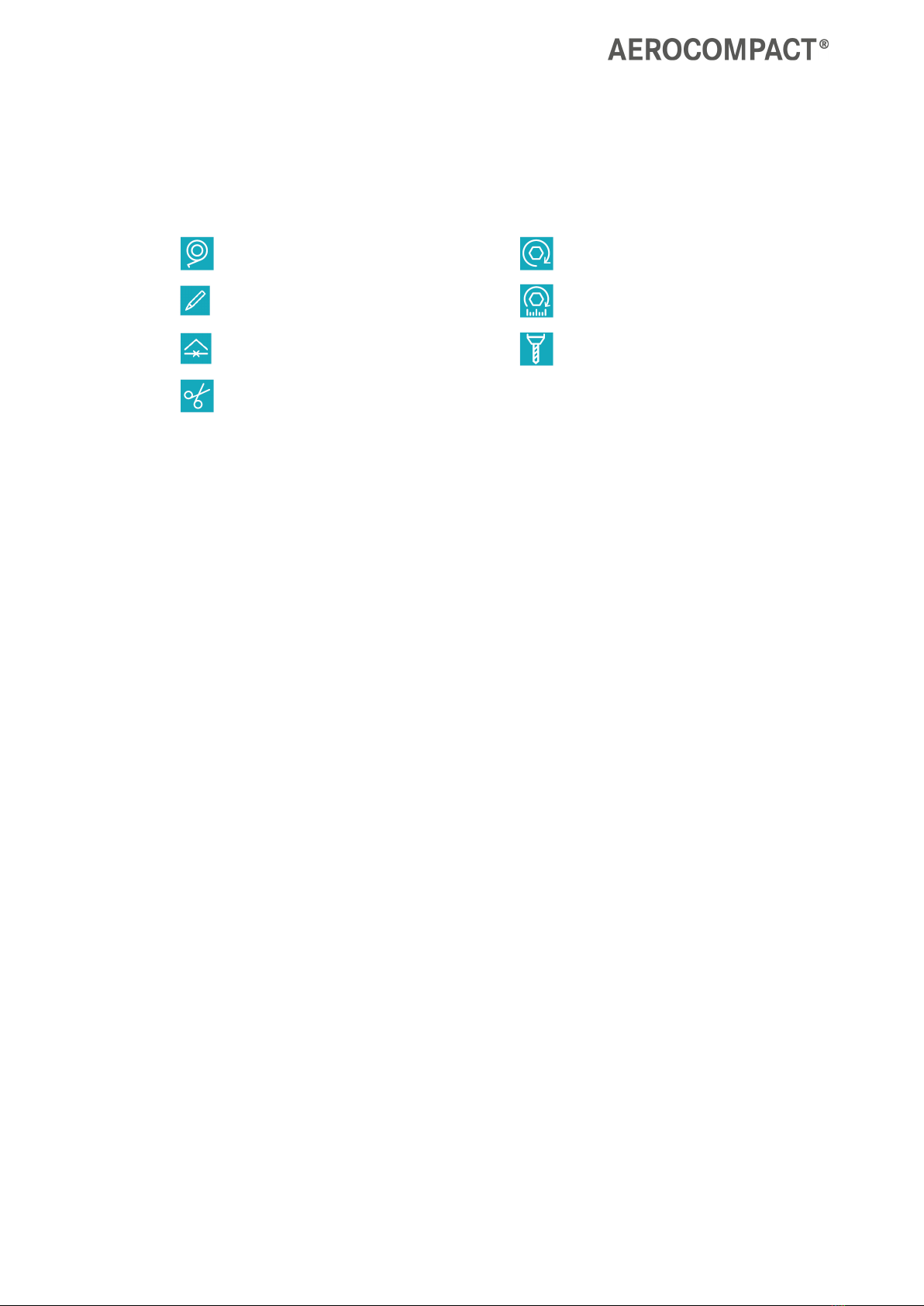
Basic components GS15
1End clamp, varying clamp height for 30 - 50 mm frame heights | CLEG10-XX
2End bracket GS15 | G1S5EB
3Connector bracket GS15, shading angle 18°/25° | GS15CNS
4Front bracket GS15, | GS15FB
5Mid clamp, for 30 - 50 mm frame heights | CLMG10
+
+
+
+
+
+
+
+
+
+
+
+
+
+
+
+
+
+
+
+
+
+
+
+
+
+
+
+
+
+
+
+
+
+
+
+
+
+
+
+
+
+
+
+
+
+
+
+
+
+
+
+
+
+
+
+
+
+
+
+
+
+
+
+
+
+
+
+
+
+
+
+
+
+
+
+
+
+
+
+
+
+
+
+
+
+
+
+
+
+
+
+
+
+
+
+
+
+
+
+
+
+
+
+
+
+
+
+
+
+
+
+
+
+
+
+
+
+
+
+
+
+
+
+
+
+
+
+
+
+
+
+
+
+
+
+
+
+
+
+
+
+
+
+
+
+
+
+
+
+
+
+
+
+
+
+
+
+
+
+
+
+
+
+
+
+
+
+
+
+
+
+
+
+
+
+
+
+
+
+
+
+
+
+
+
+
+
+
+
+
+
+
+
+
+
+
+
+
+
+
+
+
+
+
+
+
+
+
+
+
+
+
+
+
+
+
+
+
+
+
+
+
+
+
+
+
+
+
+
+
+
+
+
+
+
+
+
+
+
+
+
+
+
+
+
+
+
+
+
+
+
+

GS15
System Overview
www.aerocompact.com 12
Ballasting
1Long ballast tray | BT-1800, BT-2050, BT-2300
2Short ballast tray | BT-880
3Tapping combi screw M8x20 | SCS8x20
Accessories
1Cable conduit | CP-430, CP-620, CP-840
2Bracket for cable conduit | BR-CP
3Roof protection pad 290 x 100 x 3.8 | PP290/100
4Cable Tie Clip for Module Frame | CLP-M
Accessories for grounding / potential equalization
(USA)
+
+
+
+
+
+
+
+
+
+
+
+
+
+
+
+
+
+
+
+
+
+
+
+
+
+
+
+
+
+
+
+
+
+
+
+
+
+
+
+
+
+
+
+
+
+
+
+
+
+
+
+
+
+
+
+
+
+
+
+
+
+
+
+
+
+
+
+
+
+
+
+
+
+
+
+
+
+
+
+
+
+
+
+
+
+
+
+
+
+
+
+
+
+
+
+
+
+
+
+
+
+
+
+
+
+
+
+
+
+
+
+
+
+
+
+
+
+
+
+
+
+
+
+
+
+
+
+
+
+
+
+
+
+
+
+
+
+
+
+
+
+
+
+
+
+
+
+
+
+
+
+
+
+
+
+
+
+
+
+
+
+
+
+
+
+
+
+
+
+
+
+
+
+
+
+
+
+
+
+
+
+
+
+
+
+
+
+
+
+
+
+
+
+
+
+
+
+
+
+
+
+
+
+
+
+
+
+
+
+
+
+
+
+
+
+
+
+
+
+
+
+
+
+
+
+
+
+
+
+
+
+
+
+
+
+
+
+
+
+
+
+
+
+
+
+
+
+
+
+
+
+

GS15
System Overview
www.aerocompact.com 13
1Grounding lug with nut (follows UL 476 or UL 2703 requirements) | GL18N
+
+
+
+
+
+
+
+
+
+
+
+
+
+
+
+
+
+
+
+
+
+
+
+
+
+
+
+
+
+
+
+
+
+
+
+
+
+
+
+
+
+
+
+
+
+
+
+
+
+
+
+
+
+
+
+
+
+
+
+
+
+
+
+
+
+
+
+
+
+
+
+
+
+
+
+
+
+
+
+
+
+
+
+
+
+
+
+
+
+
+
+
+
+
+
+
+
+
+
+
+
+
+
+
+
+
+
+
+
+
+
+
+
+
+
+
+
+
+
+
+
+
+
+
+
+
+
+
+
+
+
+
+
+
+
+
+
+
+
+
+
+
+
+
+
+
+
+
+
+
+
+
+
+
+
+
+
+
+
+
+
+
+
+
+
+
+
+
+
+
+
+
+
+
+
+
+
+
+
+
+
+
+
+
+
+
+
+
+
+
+
+
+
+
+
+
+
+
+
+
+
+
+
+
+
+
+
+
+
+
+
+
+
+
+
+
+
+
+
+
+
+
+
+
+
+
+
+
+
+
+
+
+
+
+
+
+
+
+
+
+
+
+
+
+
+
+
+
+
+
+
+
GS15
System Overview
www.aerocompact.com 14
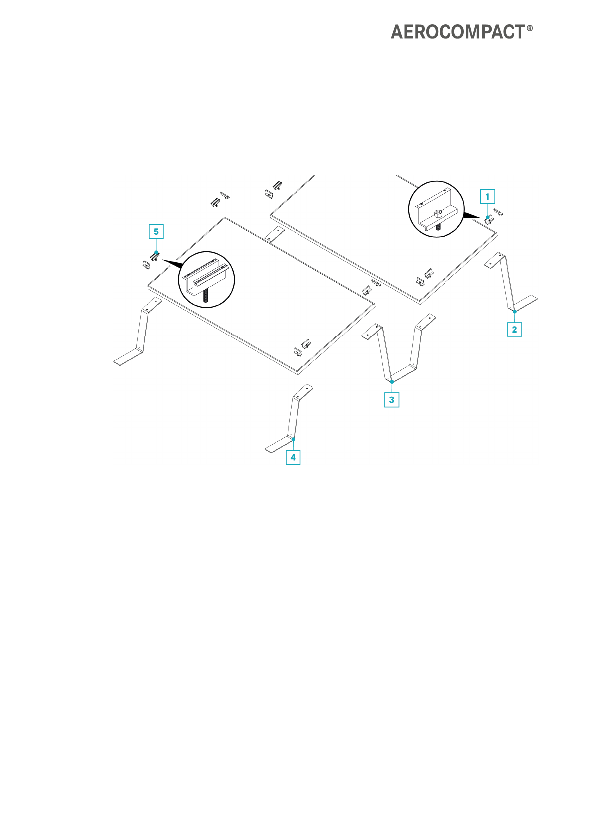
Variants
System GS15 21.85 in. inter-row | 25° shading angle | 15.75 in. ground clearance
+
+
+
+
+
+
+
+
+
+
+
+
+
+
+
+
+
+
+
+
+
+
+
+
+
+
+
+
+
+
+
+
+
+
+
+
+
+
+
+
+
+
+
+
+
+
+
+
+
+
+
+
+
+
+
+
+
+
+
+
+
+
+
+
+
+
+
+
+
+
+
+
+
+
+
+
+
+
+
+
+
+
+
+
+
+
+
+
+
+
+
+
+
+
+
+
+
+
+
+
+
+
+
+
+
+
+
+
+
+
+
+
+
+
+
+
+
+
+
+
+
+
+
+
+
+
+
+
+
+
+
+
+
+
+
+
+
+
+
+
+
+
+
+
+
+
+
+
+
+
+
+
+
+
+
+
+
+
+
+
+
+
+
+
+
+
+
+
+
+
+
+
+
+
+
+
+
+
+
+
+
+
+
+
+
+
+
+
+
+
+
+
+
+
+
+
+
+
+
+
+
+
+
+
+
+
+
+
+
+
+
+
+
+
+
+
+
+
+
+
+
+
+
+
+
+
+
+
+
+
+
+
+
+
+
+
+
+
+
+
+
+
+
+
+
+
+
+
+
+
+
+

GS15
Assembly
www.aerocompact.com 15
ASSEMBLY
Attach roof protection pad (optional)
The roof protection pad is used for all roof coverings, except for green roofs.
Make sure that the underside of the brackets is clean, dry, and free of grease and dust. Wipe the under-
side with a clean and dry cloth.
For the bracket, make sure that the roof protection pad covers the edge in each case: A = 10 mm.
Depending on the design of the connector bracket, attach 1 to 2 roof protection pads.
+
+
+
+
+
+
+
+
+
+
+
+
+
+
+
+
+
+
+
+
+
+
+
+
+
+
+
+
+
+
+
+
+
+
+
+
+
+
+
+
+
+
+
+
+
+
+
+
+
+
+
+
+
+
+
+
+
+
+
+
+
+
+
+
+
+
+
+
+
+
+
+
+
+
+
+
+
+
+
+
+
+
+
+
+
+
+
+
+
+
+
+
+
+
+
+
+
+
+
+
+
+
+
+
+
+
+
+
+
+
+
+
+
+
+
+
+
+
+
+
+
+
+
+
+
+
+
+
+
+
+
+
+
+
+
+
+
+
+
+
+
+
+
+
+
+
+
+
+
+
+
+
+
+
+
+
+
+
+
+
+
+
+
+
+
+
+
+
+
+
+
+
+
+
+
+
+
+
+
+
+
+
+
+
+
+
+
+
+
+
+
+
+
+
+
+
+
+
+
+
+
+
+
+
+
+
+
+
+
+
+
+
+
+
+
+
+
+
+
+
+
+
+
+
+
+
+
+
+
+
+
+
+
+
+
+
+
+
+
+
+
+
+
+
+
+
+
+
+
+
+
+

GS15
Assembly
www.aerocompact.com 16
Remove protective paper.
Attach adhesive surface to the underside of the
bracket.
Pre-install the clamps
Attach end-clamps or mid-clamps to the front brackets, back brackets, and connector brackets as
needed.
+
+
+
+
+
+
+
+
+
+
+
+
+
+
+
+
+
+
+
+
+
+
+
+
+
+
+
+
+
+
+
+
+
+
+
+
+
+
+
+
+
+
+
+
+
+
+
+
+
+
+
+
+
+
+
+
+
+
+
+
+
+
+
+
+
+
+
+
+
+
+
+
+
+
+
+
+
+
+
+
+
+
+
+
+
+
+
+
+
+
+
+
+
+
+
+
+
+
+
+
+
+
+
+
+
+
+
+
+
+
+
+
+
+
+
+
+
+
+
+
+
+
+
+
+
+
+
+
+
+
+
+
+
+
+
+
+
+
+
+
+
+
+
+
+
+
+
+
+
+
+
+
+
+
+
+
+
+
+
+
+
+
+
+
+
+
+
+
+
+
+
+
+
+
+
+
+
+
+
+
+
+
+
+
+
+
+
+
+
+
+
+
+
+
+
+
+
+
+
+
+
+
+
+
+
+
+
+
+
+
+
+
+
+
+
+
+
+
+
+
+
+
+
+
+
+
+
+
+
+
+
+
+
+
+
+
+
+
+
+
+
+
+
+
+
+
+
+
+
+
+
+

GS15
Assembly
www.aerocompact.com 17
Measure area, place brackets and connector brackets
Take the dimensions of the array field from the planning documents.
Measure the length of the array field and mark the line.
Measure the width of the array field and mark the line.
Place brackets and connector brackets in the array field :
Vertical field edge: Place front brackets, end brackets and connector brackets with end-clamps pre-
installed.
Field interior: Place front brackets, end brackets and connector brackets with mid-clamps pre-installed.
+
+
+
+
+
+
+
+
+
+
+
+
+
+
+
+
+
+
+
+
+
+
+
+
+
+
+
+
+
+
+
+
+
+
+
+
+
+
+
+
+
+
+
+
+
+
+
+
+
+
+
+
+
+
+
+
+
+
+
+
+
+
+
+
+
+
+
+
+
+
+
+
+
+
+
+
+
+
+
+
+
+
+
+
+
+
+
+
+
+
+
+
+
+
+
+
+
+
+
+
+
+
+
+
+
+
+
+
+
+
+
+
+
+
+
+
+
+
+
+
+
+
+
+
+
+
+
+
+
+
+
+
+
+
+
+
+
+
+
+
+
+
+
+
+
+
+
+
+
+
+
+
+
+
+
+
+
+
+
+
+
+
+
+
+
+
+
+
+
+
+
+
+
+
+
+
+
+
+
+
+
+
+
+
+
+
+
+
+
+
+
+
+
+
+
+
+
+
+
+
+
+
+
+
+
+
+
+
+
+
+
+
+
+
+
+
+
+
+
+
+
+
+
+
+
+
+
+
+
+
+
+
+
+
+
+
+
+
+
+
+
+
+
+
+
+
+
+
+
+
+
+
GS15
Assembly
www.aerocompact.com 18
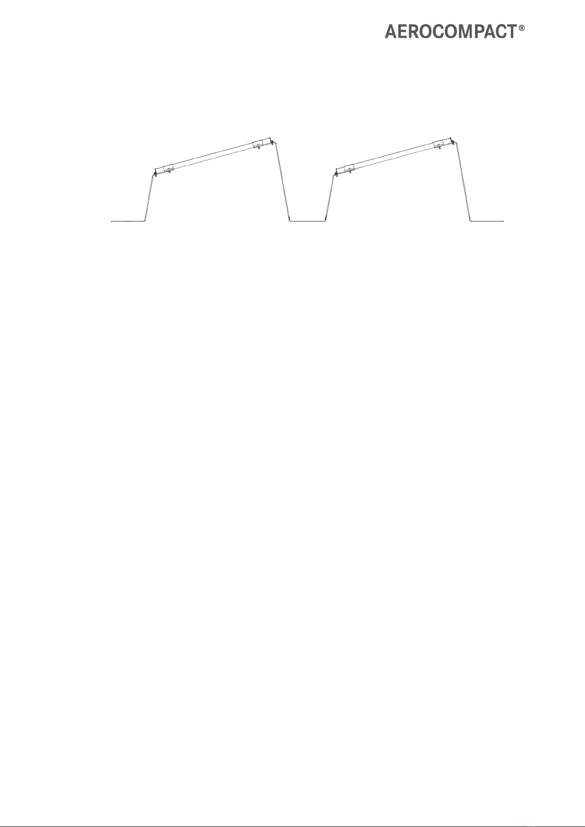
Installing the modules
Tip: When installing, wire the modules at the same time.
The cables can be attached to the module with the cable tie clip (CLP-M).
The distance between the clamps is determined by the brackets and connector brackets or by the mod-
ule size.
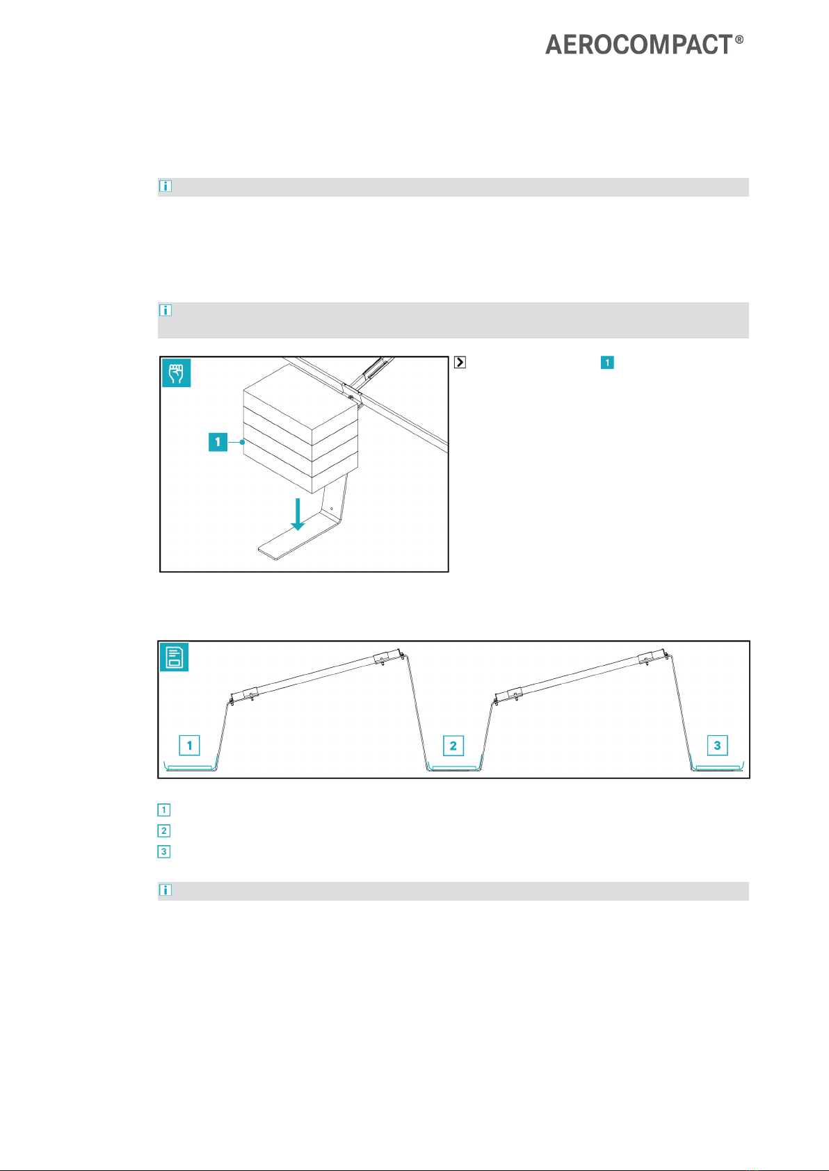
Hold the front brackets in place with a ballast block .
Place the module on the front brackets and connector brackets .
Position each module flush with the end clamps and loosely tighten the screws.
Tighten the screws of the side end clamps with 20 Nm or 14.75 ft lbs.
+
+
+
+
+
+
+
+
+
+
+
+
+
+
+
+
+
+
+
+
+
+
+
+
+
+
+
+
+
+
+
+
+
+
+
+
+
+
+
+
+
+
+
+
+
+
+
+
+
+
+
+
+
+
+
+
+
+
+
+
+
+
+
+
+
+
+
+
+
+
+
+
+
+
+
+
+
+
+
+
+
+
+
+
+
+
+
+
+
+
+
+
+
+
+
+
+
+
+
+
+
+
+
+
+
+
+
+
+
+
+
+
+
+
+
+
+
+
+
+
+
+
+
+
+
+
+
+
+
+
+
+
+
+
+
+
+
+
+
+
+
+
+
+
+
+
+
+
+
+
+
+
+
+
+
+
+
+
+
+
+
+
+
+
+
+
+
+
+
+
+
+
+
+
+
+
+
+
+
+
+
+
+
+
+
+
+
+
+
+
+
+
+
+
+
+
+
+
+
+
+
+
+
+
+
+
+
+
+
+
+
+
+
+
+
+
+
+
+
+
+
+
+
+
+
+
+
+
+
+
+
+
+
+
+
+
+
+
+
+
+
+
+
+
+
+
+
+
+
+
+
+

GS15
Assembly
www.aerocompact.com 19
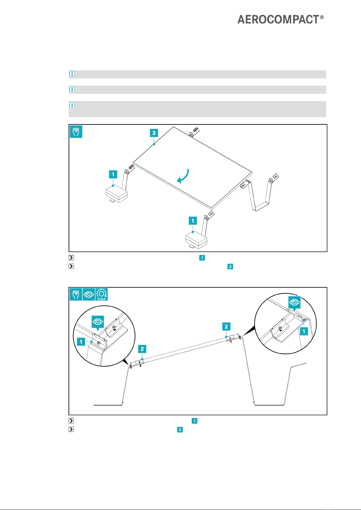
Place the next module .
Align the module flush at the upper and lower end clamps .
Tighten the screws at the mid clamps between the modules with 20 Nm or 14.75 ft lbs.
Tighten the screws on the upper and lower end clamps of the mounted modules with 20 Nm or 14.75
ft lbs.
Install remaining modules according to the recommended sequence.
Tighten the screws at the clamps with 20 Nm or 14.75 ft lbs each.
+
+
+
+
+
+
+
+
+
+
+
+
+
+
+
+
+
+
+
+
+
+
+
+
+
+
+
+
+
+
+
+
+
+
+
+
+
+
+
+
+
+
+
+
+
+
+
+
+
+
+
+
+
+
+
+
+
+
+
+
+
+
+
+
+
+
+
+
+
+
+
+
+
+
+
+
+
+
+
+
+
+
+
+
+
+
+
+
+
+
+
+
+
+
+
+
+
+
+
+
+
+
+
+
+
+
+
+
+
+
+
+
+
+
+
+
+
+
+
+
+
+
+
+
+
+
+
+
+
+
+
+
+
+
+
+
+
+
+
+
+
+
+
+
+
+
+
+
+
+
+
+
+
+
+
+
+
+
+
+
+
+
+
+
+
+
+
+
+
+
+
+
+
+
+
+
+
+
+
+
+
+
+
+
+
+
+
+
+
+
+
+
+
+
+
+
+
+
+
+
+
+
+
+
+
+
+
+
+
+
+
+
+
+
+
+
+
+
+
+
+
+
+
+
+
+
+
+
+
+
+
+
+
+
+
+
+
+
+
+
+
+
+
+
+
+
+
+
+
+
+
+
GS15
Assembly
www.aerocompact.com 20
Place ballast
Depending on the project circumstances, ballast requirements will vary.
Version 1: Ballasting directly on the brackets or connector brackets
With this ballasting option, the ballast blocks are placed directly on the brackets or connector bracket.
Take note of the exact number and position of the ballast blocks from the AEROTOOL planning doc-
uments.
Place the ballast blocks .
Version 2: Short ballast trays
The short ballast tray can be installed in the following positions:
at the front bracket.
on the connector bracket.
at the end bracket.
Refer to the Aerotool planning documents for the exact number and position of the short ballast trays.
+
+
+
+
+
+
+
+
+
+
+
+
+
+
+
+
+
+
+
+
+
+
+
+
+
+
+
+
+
+
+
+
+
+
+
+
+
+
+
+
+
+
+
+
+
+
+
+
+
+
+
+
+
+
+
+
+
+
+
+
+
+
+
+
+
+
+
+
+
+
+
+
+
+
+
+
+
+
+
+
+
+
+
+
+
+
+
+
+
+
+
+
+
+
+
+
+
+
+
+
+
+
+
+
+
+
+
+
+
+
+
+
+
+
+
+
+
+
+
+
+
+
+
+
+
+
+
+
+
+
+
+
+
+
+
+
+
+
+
+
+
+
+
+
+
+
+
+
+
+
+
+
+
+
+
+
+
+
+
+
+
+
+
+
+
+
+
+
+
+
+
+
+
+
+
+
+
+
+
+
+
+
+
+
+
+
+
+
+
+
+
+
+
+
+
+
+
+
+
+
+
+
+
+
+
+
+
+
+
+
+
+
+
+
+
+
+
+
+
+
+
+
+
+
+
+
+
+
+
+
+
+
+
+
+
+
+
+
+
+
+
+
+
+
+
+
+
+
+
+
+
+
Table of contents
Other AEROCOMPACT Inverter manuals


Popular Inverter manuals by other brands


Sofar solar
Sofar solar HYD 5KTL-3PH user manual

WhisperPower
WhisperPower W-SQ25 user manual

FRONIUS
FRONIUS Smart Meter 240V-3 UL operating instructions

APsystems
APsystems YC500A Installation & user manual

Power House
Power House PH2400PRi/E owner's manual

Delta
Delta M250HV Operation and installation manual


