Aerocool PMI WCBW4000 User manual

WINDOW COOLER MODEL
OWNER’SGUIDE
USE AND CARE MANUAL
1-999-2542 Date: 03/16
Safety
Installation
Start-up
Operation
Maintenance
Troubleshooting
WARNING - TO REDUCE THE RISK OF FIRE, ELECTRIC
SHOCK, OR INJURY TO PERSONS, OBSERVE THE FOLLOWING.
Read all instructions carefully before installation.
This cooler must be connected to 120 Volt AC, 60 Hz (cycle)
power only. NOTE: Improper voltage will void the pump and/or
motor warranties and may cause serious personal injury or
property damage.
This cooler must be plugged into a GFCI protected receptacle,
which has been properly installed in accordance with all local
and national codes. If you are not sure that the receptacle is
GFCI protected, consult with a qualified electrician.
This cooler is equipped with a power cord having an equipment
grounding conductor and grounding plug. Do not attempt to
defeat this safety device by removing the grounding pin.
Use of an extension cord is not recommended.
Do not operate if plug or cord is damaged in any way. If the unit
is damaged or malfunctions, do not continue to operate it.
Always disconnect electrical power to unit before attempting to
work on or service your cooler.
Some models may have a restricting orifice in the pump water
tube to assure proper water flow rate to the pad. Do not remove
this restrictor!
Remove the plug from the electrical receptacle by pulling on
the plug and not the cord.
Do not operate this blower (fan) motor with any solid-state
speed control device.
Do not operate this unit with pad frame(s) and/or air outlet grille
removed, this may cause the fan motor to overload and
damage the motor.
NOTE:
Do not locate unit near exhaust or vent pipes as odors or fumes
may be drawn into cooler.
Use of anode devices, chemical additives or treatments in this
cooler will void the warranty.
Your warranty does not cover shipping damage. Report all
shipping damage at once to dealer or carrier making the delivery.
For future reference, record the model and serial numbers, date
and place of purchase of your evaporative cooler here:
Model #
Serial #
Date of Purchase:
Place of Purchase:
Congratulations: You have purchased a product of superior performance and design,
which will give the best service when properly installed, operated and maintained.
This guide will provide you with information needed to mount, operate, inspect, maintain,
and troubleshoot yourAerocool water conservation window cooler.
The first section, Installation and Start-Up, gives details for installation. The second
section, Maintenance, contains operational and maintenance instructions, while
Troubleshooting includes information on commonly encountered problems.
INSTALLER: Please deliver this guide to owner.
Model: WCBW4000
Water Conservation Cooler
PHOENIX MANUFACTURING, INC.

2 Evaporative Window Cooler Use and Care Manual
INTRODUCTION
Your Aerocool evaporative air cooler was thoroughly tested and
inspected before leaving the factory. This manual is your guide to
proper installation procedures along with information about
reasonable care and maintenance that will ensure safe, economical
and trouble free cooling. Failure to follow these instructions may
damage your cooler, impair its operation, create the potential for
serious personal injury and/or void the warranty.
Read it carefully.
ANote About Air Exhausting / Maximum Cooling
To get the maximum capacity of your cooler, and to help
keep insects, dust, dirt, etc out of the cooled space, the house should
be maintained at a slightly positive air pressure (that is, there should
be slightly more air going into the house than is leaving). This is
controlled by how much the windows or doors are opened.
INSTALLATION
Carefully read the contents of this manual and review the
drawings of the cooler to familiarize yourself with the various
parts before beginning the installation process.
CAUTION: Disconnect all electrical power to the cooler
before attempting to install, open, or service your cooler.
Even while routinely inspecting or servicing the inside, the cooler can
be accidentally started. Keep people and pets away from the cooler
and electrical supply when you are working on it. Before opening,
servicing or cleaning the unit, unplug the unit from the wall receptacle
and take steps to ensure that the cord cannot be plugged back in and
the cooler turned on accidentally. Do not plug power cord into the wall
receptacle until installation or service work is complete.
Before attempting to install the cooler, confirm that the following
preparations have been made:
This cooler must be plugged into a 120 volt GFCI (Ground Fault
Circuit Interrupter) protected receptacle. If you are not sure that
the receptacle is GFCI protected, consult with a qualified
electrician. This receptacle should be located within 5 feet of the
window opening (cooler power cord is 6 feet long. Use of
extension cords is not recommended).
Install cooler in a window where only fresh outside air can enter.
Avoid installing the cooler in an area where the free air
movement around and into the cooler is restricted or locations
where obnoxious odors or fumes may be drawn into cooler from
vent pipes, kitchen exhausts, etc.
Verify that the supporting surface is strong enough to bear the
weight of the cooler when in use. This unit will weigh
approximately 250 pounds when operating at full capacity.
Verify that the supporting surface is level in all directions.
Since coolers function best when there are plenty of openings for the
air to exhaust, you can leave doors or windows open so your house
can breathe.
How much should you open your windows or doors? You should
adjust your openings until the air pressure inside the house is
nearly balanced with the air outside. A good method to determine
when the air is reasonably balanced is to place a tissue paper
against the screen in the window or door farthest from the cooler
and adjust the other openings in the house until the tissue paper
stays lightly on the screen. You can adjust different windows in the
house to direct the most airflow to the areas that are occupied
during different times of the day or night (example: living room
windows during the daytime, bedroom windows at night.)
HINT: To avoid a rush of warm air when starting the cooler be sure to
turn on the pump for a few minutes to completely wet out the pads
before starting the blower.
Platform or Stand Mounting
See
illustration (Fig. 1) for a typical installation. Construct a platform or
stand below the window strong enough to support the weight of the
cooler (approximately 250 pounds).
Measure and construct a level platform or stand that will allow the
bottom surface of the cooler duct to rest on the window sill. Allow
clearance for the drain/overflow standpipe connection.
Position the cooler so that the duct rests on the window sill and the
grille flanges are inside the window frame. DO NOT drive nails or
screws through bottom pan into mounting surface, this will
void the warranty.
Lower the window to rest on the top of the duct (vertically hung
windows) or slide window closed against side of duct (horizontal
slider windows). Block any remaining unused portion of the
window opening with a suitable blocking material (Plexiglas, solid
plastic sheet, solid wood panel, etc.). It will be necessary to seal
any joints around the duct to prevent entry of rain, dust/dirt,
insects, etc. Any good quality caulking or foam tape will work.
Installation normally involves locating the unit in a suitable window
and the construction of a platform or stand to support the weight of the
cooler. Since every installation is different, the exact requirements to
mount and seal a cooler against the weather will be best determined
by the location and at the time of the installation. Most installations will
require blocking of the unused portion of the window around the duct
or other modifications to the window frame may be necessary.
Figure 1
Figure 2

Belt Tension Adjustment
CAUTION: Disconnect all electrical power to the cooler
and insure that belt is not rotating before adjusting belt
tension.
Correct belt tension and alignment is
important, proper setup reduces power
consumption and prolongs life of belt and
motor. Check belt tension by squeezing belt.
Proper tension will allow deflection of ½ to ¾
inch. To increase or decrease belt tension,
loosen bolt in slot of motor support bracket.
Adjust belt to proper tension and retighten bolt.
CAUTION: Never operate unit with
pad frame(s) and/or air outlet grille
removed. This will result in an
overloaded condition and may
damage the motor.
Mounting Using Chain Kit
See
illustration (Fig. 2) for a typical installation. Remember, the framing
around the window must be strong enough to support the weight of the
cooler (approximately 250 pounds).
Chain Kit contains:
2 - Screw Hooks 2 - “S” Hooks
2 - Leg Leveling Bolts 2 - Rubber Pads
4 - 3/8” Square Nuts 4 - 3/8” Washers
2 - Hanger Straps 2 - #10-24 x 1/2” long Bolts
2 - #10-24 Nuts 2 - 5 ‘ Long Chain
Install chain kit as follows:
Attach screw hooks to outside window frame approximately two
feet above top of cooler. Be sure hooks are inserted to full depth in
window framing for maximum strength.
Attach chain to each hook.
Attach hanging straps to top of rear corner support legs in the 3/16”
diameter holes using the #10-24 bolts and nuts provided. Install
“S” hooks in straps.
Place leg leveling bolts through 7/16” diameter holes in bottom of
front corner support legs. Use nut and washer on outside of
cabinet and install rubber pads on outside ends of leveling bolts.
Place second nut and washer on leveling bolts inside cabinet.
Position the cooler so that the duct rests on the window sill and the
grille flanges are inside the window frame, allowing the “Z” shaped
bracket, located under the grille, to rest on the window sill and butt
against inside of window sill flange. Connect “S” hooks and screw
hooks to chain links that bring the cooler closest to a level position.
Use leg leveling bolts to brace the cooler away from the wall.
Adjust bolts and chain to level cooler. NOTE: Cooler may need to
be re-leveled to compensate for the added weight of water.
Tighten nuts on leveling bolts inside cabinet.
Lower the window to rest on the top of the duct (vertically hung
windows) or slide window closed against side of duct (horizontal
slider windows). Block any remaining unused portion of the
window opening with a suitable blocking material (Plexiglas, solid
plastic sheet, solid wood panel, etc.). It will be necessary to seal
any joints around the duct to prevent entry of rain, dust/dirt,
insects, etc. Any good quality caulking or foam tape will work.
An alternate installation method involves locating the unit in a suitable
window and using the included chain mounting kit to support the
weight of the cooler. As with platform or stand mounting, every
installation will be different. The exact requirements to mount and seal
a cooler against the weather will be best determined by the location
and at the time of the installation. Most installations will require
blocking of the unused portion of the window around the duct, or other
modifications to the window frame may be necessary.
Install Overflow Standpipe / Drain Line
Install overflow drain bushing in bottom of cooler as follows:
Slide rubber washer over drain bushing.
Push drain bushing through bottom of
cooler, assemble and tighten lock nut.
Screw plastic overflow standpipe into
the drain bushing and tighten snugly
(hand tight) to prevent leakage.
Connect a suitable drain line (copper /
PVC / garden hose) to drain bushing.
Never drain water onto a roof; mineral
build-up or damage to roof may occur.
NOTE: Drain water in accordance with local plumbing codes.
Connect Water Supply
CAUTION: All plumbing installations must comply with
local building and safety codes, and must be performed by
qualified personnel only.
NOTE: Coolers should not be connected to “soft” water systems. Soft
water will accelerate corrosion and decrease the effective life of pads
and cooler cabinet. Connect water line as follows:
A water supply valve should be installed at a convenient location
to allow the water supply to be turned on and off for servicing or
winterizing. Minimum 1/4“ diameter tubing should be used to
provide water to the cooler. Larger tubing is recommended if the
distance from the valve to the cooler is greater than 100 feet, then
reduced to 1/4” at the unit.
Install float valve in the bracket provided.
Connect tubing from water supply to float valve. Place
compression nut and ferrule over end of tubing, insert tube into
float valve then tighten compression nut to secure.
Evaporative Window Cooler - Use and Care Manual 3
Figure 3
OPERATION
Controls
The rocker control switches are used to select the operating mode of
the cooler. These switches control fan speed (High/Off/Low) and the
cooling (pump) operation (On/Off).
Insert the drain adaptor into the overflow standpipe as shown.

4 Evaporative Window Cooler - Use and Care Manual
GENERAL INSPECTION
Initial Start-up or Annual Inspection
CAUTION: Disconnect all electrical power to the cooler
before attempting to install, open, or service your cooler.
Before start-up of the cooler for the first time, or at the beginning of
each cooling season, make sure that all required connections,
adjustments, etc. have been made. Verify that:
PCooler mounting is level; window and duct are sealed.
PPower supply cord is correctly routed, safe and secure.
PMotor, pump, drain, float valve, air outlet grille etc. are
correctly installed and fully functional.
PWater line securely connected, turned on, no leaks noted.
PFloat adjusted for proper water level.
PPump impeller turns free and smooth. If in doubt, remove
impeller cover (see “Cleaning Pump”) and check rotation.
PBlower wheel, shaft, pulley and motor sheave bolts / set
screws are tight.
PMotor sheave / Blower pulley alignment okay; belt correctly
tensioned, blower wheel turns freely.
Start-up Check List
CAUTION: Never operate cooler with pad frame(s)
and/or air outlet grille removed. This will result in an
overloaded condition and may damage the motor.
To verify and check out the cooler installation on initial or annual start-
up, the following procedure should be followed.
POpen building exhaust / relief vents (windows, doors, etc.)
PPlug supply cord into wall receptacle. Switch cooler “ON”.
PVerify that pump starts and pads are evenly wet.
PObserve that motor starts and runs.
In case of trouble on any of these steps, refer to the Troubleshooting
Chart on
Cabinet Inspection Checklist
After initial start-up and for a few weeks afterwards, check for and/or
observe the following: Refer to the Troubleshooting Chart on f
necessary.
PLeaks from water lines, pad frames, cabinet, etc.
PCooler pads: even wetting, no dry streaks.
PConfirm water level depth setting is correct.
PVerify full, even flow in water distribution system.
PBlower wheel / motor rotates freely, no unusual noises.
PBelt condition / tension / alignment OK.
PCheck motor mounting, cabinet hardware, set screws on
pulleys, blower wheel are tight
page 6.
page 6 i
MAINTENANCE SCHEDULE
Regular maintenance and periodic inspection is the key to long and
successful service from your Aerocool cooler. The cooler should
receive major servicing at least once a year, more often if conditions
require (dusty environment, constant use, poor water quality, etc.) For
maximum cooling efficiency, long life and appearance, every two
months during operation, the cooler should be inspected and cleaned.
NOTE: Do Not Undercoat the Water Reservoir
Your cooler's water reservoir is finished with our Peblar XT®
appliance-type finish. It is so hard that asphalt-type cooler water pan
under-coatings will not stick to it. Undercoating will break free,
clogging the pump and water distribution system.
NOTE: Do not use cooler cleaners, cooler treatments, anodes or other
chemical additives in this evaporative cooler. Use of any additives or
water treatment other than the furnished bleed-off will void your
warranty and may impair the life of the cooler.
Before starting any maintenance operation, thoroughly read all
operating and maintenance instructions and observe all
cautions and warnings.
Cleaning
CAUTION: Never wash your cooler cabinet with a
garden hose; water may harm motor and pump or seep
into ductwork. Motors damaged by water are NOT covered
under warranty.
All foreign materials, mineral scale, hard water deposits, dirt, etc.
should be removed from pad frames, water pan and other
components. Your cooler's long lasting finish can be brought to like-
new condition by using warm water and a soft cloth.
NOTE: Avoid using scouring pads, steel wool or wire brushes, as
these will damage the finish and encourage corrosion.
Maintenance & Inspection
IMPORTANT: Before operating cooler at the beginning
of each cooling season, turn blower wheel, cooler motor
and pump motor shafts by hand to make sure they turn
freely. Failure to do so may result in burning out motor.
Periodic inspection of your cooler will enhance the chance for long,
trouble-free service life. For maximum efficiency, every two months
during operation, or any time the cooler is opened, the cooler should
be inspected. Some suggested items to look for:
PCheck for leaks from pad frames, cabinet, etc.
PAny dry spots or streaks on pads when pump is operating?
PAre bolts, nuts and set screws still snug?
PAre the bearings, etc., making any unusual noises?
PDoes the blower wheel turn freely?
PIs float level set correctly?
PIs water in the bottom pan clean?
PBelt condition / tension / alignment OK?
Adjust Belt Tension
Each time you inspect your cooler, be sure to check belt tension on
motor and blower assembly. Check belt condition and replace it if
frays or cracks appear. Check alignment of blower pulley with motor
pulley (see page 3 for detailed steps).

Cleaning Water Pump & Hose
CAUTION: Disconnect all electrical power to the cooler
before attempting to install, open, or service your cooler.
CAUTION: Do not allow pump to fall over and become
submerged; water will damage pump motor.
Clean water pump, drain pump, and hose assembly as follows:
Unplug pump cord, remove
mounting bracket screw and
remove pump from cooler. Shake
gently to remove water.
To prevent breakage, carefully
release the snap-out impeller
cover plate and remove cover
plate from the pump body.
Using a mild detergent solution and a
soft cloth, clean deposits from screen,
around impeller and cover plate. Spin
impeller to dislodge any remaining
foreign material.
Remove any foreign material in the hose adapter
(between the pump and hose), or between the hose
and the water distributor assembly.
Rinse and reinstall impeller cover plate.
Reinstall pump and reconnect pump cord.
Draining
Drain the cooler for cleaning or at the end of the season as follows:
Unplug cooler power supply cord from wall receptacle.
Turn off water supply and remove pad frames.
Connect a drain hose to the drain fitting on the bottom of the
reservoir, if not already connected to drain line.
Remove overflow standpipe from the drain fitting.
Drain and clean reservoir. Remove any remaining water with
a rag or sponge.
Touch-Up
The hardness, adhesion and smoothness of the internal and external
finish on your cooler makes it extremely unlikely that scratches or
chipping will occur. In the event that finish damage does occur, it
should be promptly repaired by the following procedures:
1. Sand the area around bare metal spots.
2. Prime and paint with a quality paint.
Do not use asphalt type cooler undercoat material in water
reservoir. Undercoat will break free, clogging the pump and
water distributor.
Lubrication
Motor Bearings
Some motors used in Aerocool coolers have ports for lubricating the
motor and are oiled at the factory. If the need for oiling is indicated, see
individual motor nameplate for specific instructions on re-lubricating
the motor. Under normal use, these motors require oiling about every
12 months of operation. Do Not Over-Oil.
**Advanced Controls**
This unit is equipped with a water saving device. The advanced
controls within the cooler will cycle the cooling pump to reduce water
usage. It is normal for the cooling pump to cycle on and off for short
periods of time while the unit is running.
Evaporative Window Cooler - Use and Care Manual 5
Blower Shaft Bearings
Blower shaft bearings need periodic lubrication. They should be
checked 20-30 days after initial start-up of operation. The oil cups on
the bearings should be filled with a good grade of SAE 20W or 30W
non-detergent oil when necessary. Under normal use, oiling is
required every three months of operation. Do Not Over- Oil.
Pump Motor Bearings
The pump motor does not require lubrication.
Changing Cooler Pads
CAUTION: Disconnect all electrical power to the cooler
before attempting to install, open, or service your cooler.
The condition of your cooler pads should be checked at least once a
year; at the beginning of the season is the best. However, your pads
may need to be checked more frequently, depending on the local air
and water conditions. For instance, in areas where mineral content of
the water is high or the air is dusty, deposits may build up in the cooler
pads, restricting airflow. Clean or replace pads as follows:
1. Disconnect power from the unit.
2. Remove pad frame assembly from the cabinet.
3. Lay pad frame on smooth, flat surface with pad retainer up.
Observe the location/placement of the pad retainer. Remove the
retainer by sliding it out from under the pad frame flange. Carefully
remove and discard old pad.
4. Using a mild detergent, wash dirt and scale from pad frame and
rinse with fresh water. Check slots at top of pad frame to be sure they
are open and clear. Wire brushing is not recommended. If finish is
damaged or rusting is noted, repair area as noted in the “Touch-Up”
section.
5. Place the slot in the end of the new pad over the bottom flange of
the pad frame and push the pad down against the flange until it stops.
Gently push the top of the pad into the pad frame. Slide the 1” thick
pad on top of the large pad already in place. Replace the pad retainer
by sliding the retainer under the pad frame flanges.
6. Pre-soak pad. (this will help with the wetting of the pad on start up)
Reinstall pad frame assembly into unit.
REPLACEMENT PARTS
When ordering replacement parts, always refer to the serial and
model number of your cooler. Use the part numbers listed in the
accompanying parts list, as illustrated in the diagrams for your model.
Winter Shut Down:
- Always drain all of the water out of the cooler and water supply line
when not in use for prolonged periods, and particularly at the end of
the season. Keep the water line disconnected from both the cooler
and the water supply so it does not freeze.
- Disconnect power from cooler during extended periods of non-use.

Adjust float to 2 1/2“ water depth
Free float from obstruction
Replace float assembly
Remove obstruction
Replace water pump
Locate and free obstruction
Clear debris from trough
Replace switch
Repair or replace non-functional wiring
Turn on water supply
Check power receptacle and cord
Adjust belt tension
Replace motor
Replace switch
Replace belt
Open windows to increase air flow
Adjust belt tension or replace if needed
Replace pads
Re-install pad frame(s) or air outlet grille
Check voltage
Adjust belt tension
Oil or replace bearings
Oil bearings
Reposition wheel
Tighten set screws
Open doors and windows to increase ventilation
Float valve out of adjustment
Float movement obstructed
Float valve non-functional
Pump intake clogged
Water pump non-functional
Clogged water line
Pad trough clogged
Switch non-functional
Wiring non-functional
Water turned off to cooler
Electrical power disconnected
Belt too loose or too tight
Defective motor
Defective switch
Broken belt
Low voltage
Excessive belt tension
Blower shaft tight or locked
Bearings dry
Pad frame(s) or air outlet grille removed
Blower rubbing on housing
Motor sheave or blower set screws loose
Inadequate exhaust
Insufficient air exhaust
Belt too loose
Pads plugged
Water draining from unit
Dry pads
Motor does not start or no air delivery
Motor cycles on & off
Noisy operation
Excessive humidity in house
Inadequate air delivery
PROBLEM / SYMPTOM POSSIBLE CAUSE
TROUBLESHOOTING GUIDE: Should an obvious problem occur with your cooler consult the following table. If you
cannot correct the problem, or if it persists, contact qualified service personnel.
CORRECTIVE ACTION
6 Evaporative Window Cooler - Use and Care Manual
QUICKCONNECT
ADAPTOR
WIRING DIAGRAM

E ri d r a n l s
6 nf a o Evaporativo deVentana-M u a de U o y Cuidado
t a
Ajuste el floador 2 1/2“ de profundiddde agua
tLibere el flo ador de la obstrucción
mRemplace el ensa bledeflotador
l
Remueva a obstrucción
Remplace labomba
Localicey remuevalaobstrucción
Limpiela basura de las canaletas
Remplace elinterruptor
Repareo remplace alambres no funciona
lAbrir e suministro deagua
Revisar el receptáculo de corrientey el cordón
Ajustela tensión
Remplace elmotor
Remplaceel interruptor
Remplace banda
Abraventanaspara aumentar el flujo
Ajustelatensiónoremplacela
r
Remplace filt os
o
Reviseel vltaje
Ajuste la tensión
h
Lubrique o remplace lascumaceras
Lubriquecon aceitelaschumaceras
)
Reinstaleel filtro(s o rejilla
Alinearla turbina
tieAprieetorn llos opr sores
ó
Abra ventanaspara aumentarlaventilaci n
Válvudlotador fu ra de ajutelae f e s
Movi ieto dlflotado bs ridom n e r o t u
Válvu nun ion
lao f ca
Ent ada d agua de labomb tapadar e a
Bomba no funci na
o
Linea egua tap da
d a a
Canaleta de f trotap dail a
Itrrupt r no f nc onan e ou i
Al mbraono funcio a
ad n
Agua ha ia el nfriadorcerradac e
Corriete eéctricdesconctada
n l a e
Banda muy loja o ap etadaf r
Motor no funciona
I t rrupt r no f nc ona
ne o u i
Banda rota
Bajavotajel
Bandadmasia o apr tdae d e a
Ej de op dor cong lado
e s la e
Chumac ras ecas
es
Filtro(s)o rejilla del aire r movid s
e o
La turbaosa on la
cjael op dor
in r c adsla
T rnillos opre ores de lat rbino plea
os u a o
motriz muy flojos
Inade uado es ap de ire
cce a
I sufici ntescape d
aen eee ir
Banda muy lojaf
Filtros tapados
Deam
de a a e la dadrr e gu n uni
Fi t Secl ros os
No comieao hay entrega de i
nz no are
E
m tor nde paga
l o se pre y se a
Operai n rui ac ó dos
Humedad ex siva dentr de lcsace oa a
E rega de airenacuado
nt i de
PROBL MA /SÍ TM
E NO A:ROCAUSAP BABLE:
NS
inr
oe ood
sne l
TRAZADO FALLA : Su p bl ma bvi ocurreen su enfriaor, conulte la siguie ttab a. Si no
pco i p a co u e t co t ci
uede rreg rel roblem , ntacte a n repres ntan e mpe ente de servi o.
ACCI CT VA:
ÓN CORRE I
DIGRA A L B D
A M de
A AMRA O

Lm z dea mb y mang rai piea l boaue
ECACIO:PR U N De c nece o a a c r ieee écr as o tt d l o r nt l t ic
d l nfrado n e deinte ar ins alr, abr , rl
e e i r a t s nt t a iroda e
srv c sn rid
ei ioa u e f a or.
P AU I N
REC C O :pe ta q e aomb s c iga s
No rmi ul b ae a y e
sm
eja
eau
a aae
ltr
u r ;lg dñ m
oo
.
Lpo b , boaledrena g era
imie la b m a mb , lam n u
y lans m leddisib id r cm sig e:ea b etru o o o u
en u l c r ón cla ija e la
Dsech feeo d v d
bmbae ev l to n elao ,rmu a e r illo d
b
a dr de bma r e
arzae
a la o b yemuva
ntr de tap mat r l je o.
e e pa a s areia an
Rmue a ua u r m t r (aje o en e adp do
lae v c lq iea e ial n l a ta ry
ngea,o e trlaman u ra l istib idod gu .
ma u r ) n e g e y e dru r e a a
juau e sta cu iertad l elete
Eng e y r in le la b e imp n .
intlela omb n u elco d n d o a.
Resa b a y e ch fer ó e la b mb
rnnDead
o
cl eós o po limpielina e ca a tm o a a
r oa f l d d ep r dco igu:
Vaiéed p it mose
D se chfe l ordóe s m is o l r ce táulo d la pae .
enu
ec n
d
u
intr
d
e
epc e r
d
C r e e sminis o ea a a nf iaor e u va l iltr.ier l utr dg
ule r d yrme ef o
Co e elang era d d en jeneono d l d póitoi non ctmaue r a e l f d e e s , s
etáy onc o
a ne e
dea .
s ac et
ad
lalí ad rnj
e
Rme el b jede eos deo d l bu .e u va u r b a r e je
Re uv c
ulqu r
s
orn
td au
Viélimpe de ó o.
acyie l p sitm e a aie ba e e g a
n
uae oj
a
o
tao.
c
o nspn
rp
Retaroc
L u
ez,
a
de n
y
s
uvidd
dl caaoi
ntroy
e
xro
euadr a hs
i
ó a a ea bde
n t
e
n ns
nf iaor ha e qe s a e trmamee i p o ab q e la intr se
er d c u e xe da nt mr b le u p u a
rsp o spe . Enn e to uest oc r a e db rpa ar
ae e le uev nq e o u r, s e e e r
s uie d s sig iete r ce im n s
ig n o louns p o d ie to:
1. L lr a ae e or e
la r esd tal
d scie ta .
ijee á e lrd d d s pa t eme eubr s
2e inr df ndy pinura e uea ali d. Us p tua e o o t db n c da .
o e cmpues os de sf l o n ldeóso de a ua yqu seN us o t aat e epitgae
s rr,t pando b aldisr b d d agua.epa aá alaomb y e t i ui or e
UB CION
L RICA
h ce a de mot r
C uma r s l o
un s mo r s u ad s e rco l en r do e tie enceerasAlgo toe s o n Ae o o f iar s n a it
para lu r are y n lura s ela f bricaes ad or
b ics so bic do ná . Si la n ceid p
lu r ar e in ica a,apla a inivid a el mo r ara
bic s es d d ve la c d u l d to p
st ucion s ee fic s para r lu r r e o orjous o mal,in r c e spcí a e b ica lmt . Bao n r
es s toe
r q ieren lu r c n lr deo ead2 se d
to mo r s eu b icaióae d r d ca 1 me s e
oeracnNo ob - e t
s re ac i e.pió.
la bo a deefriadr. Sa d la
mb l n o cú a
ligr men e r r mov r dee a t pa a e e lal
ga.
au
Paa r ve ir q e s ubre,n
rp e n ue q ie
co
cuad
e u va la la
e b sedeid orm e p cadla a l
implen e
rme p cade laae t y
e u va lala
b se
ec r o d la bo a.
dlue p e mb
Uno un oluióndet ren e
sa d a s c e d e g t
ligea ieloep sitsdl ed zor , limp sdó o eca
d lbma
aeedr
dlimpl
e
n
e
ea
o b,lrd o e e t y
pa era d a .la ta d e la b se
irl ime
Ge e pl
nf adEpoa i e aMuneCui do 5
E ri or va r t vo deV nt na - a al d Usoy da
s
Controles Avanzado
dd
Esta unidadestáequipadacon undispositivo eahorro e agua. Los
addm
controlesvanzadosdentro elra iador iniciará elciclo dela boba
igig
de refr erac ónpara reducir el uso delaua.Esnormal que la
igió
bombade refr erac n para realizar unciclo deencendidoy apagado
t
duran e períodos cortosdetiempomientras launidadestá
funcionando.
uet a
Chmaceras del ejde la urbin
q
Laschumaceras delejede la turbina re uieren lubricación periódica.
da
Se eben revis r despuésde20-30 díasdeoperación.Las aceiteras
cnidenlashumacerassedeben llenarcon aceite de bue a calad SAE
- r e d sn
20Wo 30W nodete gent cuan o eanecesario. Bajousoormal,
slubricacióne requiere cada tresmeses deoperación.
Nosobre-aceite.
o
Chumacerasdela b mba
aá.
L s chumaceras delabomba estnpermanentementelubricadas
i s
Cambiando losf ltro(aspen)
PRECAUCION: e t c
Descon cte toda la corrienteelécri a
delenfriador antesdeintentar instalar, abrir, o darle
io oserv cia suenfriadr.
r1. Desconectela electicidad dela unidad.
l o b
2. Quitalaalmohadillade montaje debastid r del gainete.
r i3. Coloque elensamblajede elma coensuperfice lisa yplana
o c uconretenedorde almhadillaha ia arriba.Observar labicación y
rca
colocaciónde laalmohadillade eten ión. Retir r el retenedor
illdeslizándolopor debajode la almohadade labrida del bastidor.
e
Retirconcuidado ydesechela vieja pad.
4. Usando undetergentesuave,lave la suciedad y laescala del
a y a
mrcode laalmohadillaenjuague conagu fresca.Revise las
e
ranuras en laparte superior d l marco dela almohadillapara
sc
asegurarse de que sonabiertaylaras.Nose recomiendael
o scepilladode alambre.Sisedaña el acabadu oxidación e
observa,reparaciónde comoseseñalóenla secciónde
.
"Retoque"
lor m a u5. Co que la ranura en elext e odela almohadill n eva sobre
r
elreborde inferior de la estuctura dela almohadilla ypresionela
s v
almohadilla contra labrida hasta el tope. Empujeua ementela
an o lD c
parte superiorde laalmohadill e el bastid r de cojín. esli e la
lmdu
aoha illagr esa de1" encima dela almohadilla grandeya en
u o r
lugar. V elva acol ca el retenedordelcojínporel retenedor enlas
bridasde marco debotón.
. a
6Almoh dilladeremojo previo. (esto ayudará con laadherencia
s l u p
deoldadura dela almohadilla ene arranq e ara arriba)Vuelvaa
aidinstalar elarm zón almohadilla enun ad.
or
La c ndición desus almohadillas refrigeadordeberevisarse al
l
menosuna vezal año; al principiode latemporadaes e mejor
o s e
tiempo. Sin embargo, susalm hadilladeba revisars conmayor
nl d
frecuecia,dependiendode las condiciones ocales el agua y aire.
om
Preje plo, en zonas donde esalto contenido mineral delaguao
r n , u d lael aire espolvo ie to pueden acum larse más epósitos ens
in o ie
pastillas, restrgiendla circulación deaire.Limp ocambielas
e
almohadillascomo sigu :
d
Apagado e
Invierno:
Sieaa- mpre vacie todael guadel enfriador y de latubería cu ndo no
o p
esté en uso p r periodos rolongados, yparticularmente enel
a g
término dela temporada. Mantenga latuberi dela ua
sa a s sde conectadaenmbos lados praquenoe revienteen baja
temperaturas.
de
-Disconecteelenfriador ela fuent durantelargos
periodos deno uso.

Enfr ado EvaporativodeVntana -Maual de UsoyCuidado
4 i r en
I E CI
NSP CÓN
GENERAL
La incip e en o list de specón der -comizo anua
CA N:
PRE UCIOe nealaieléc iD scoctetodcorr nteetr ca
fr adoan tent r st lar, abir,o da ledel en i rtes de in a in a rr
so s eni
ervicia
u frador.
nd ed looy
ao a p r r r o e e
A tes e pr n eremtrl b mb o p ime avez, n l
iez d d p a dnrmi t ,se r s d a r
com no e ca a tem orda e e f ia en o a gúeee hbe
hch oss n n s a st s. iiq e q :
e o t da laco exioe y ju e
Yverf u ue
nue fi
a o l n n d e a s.
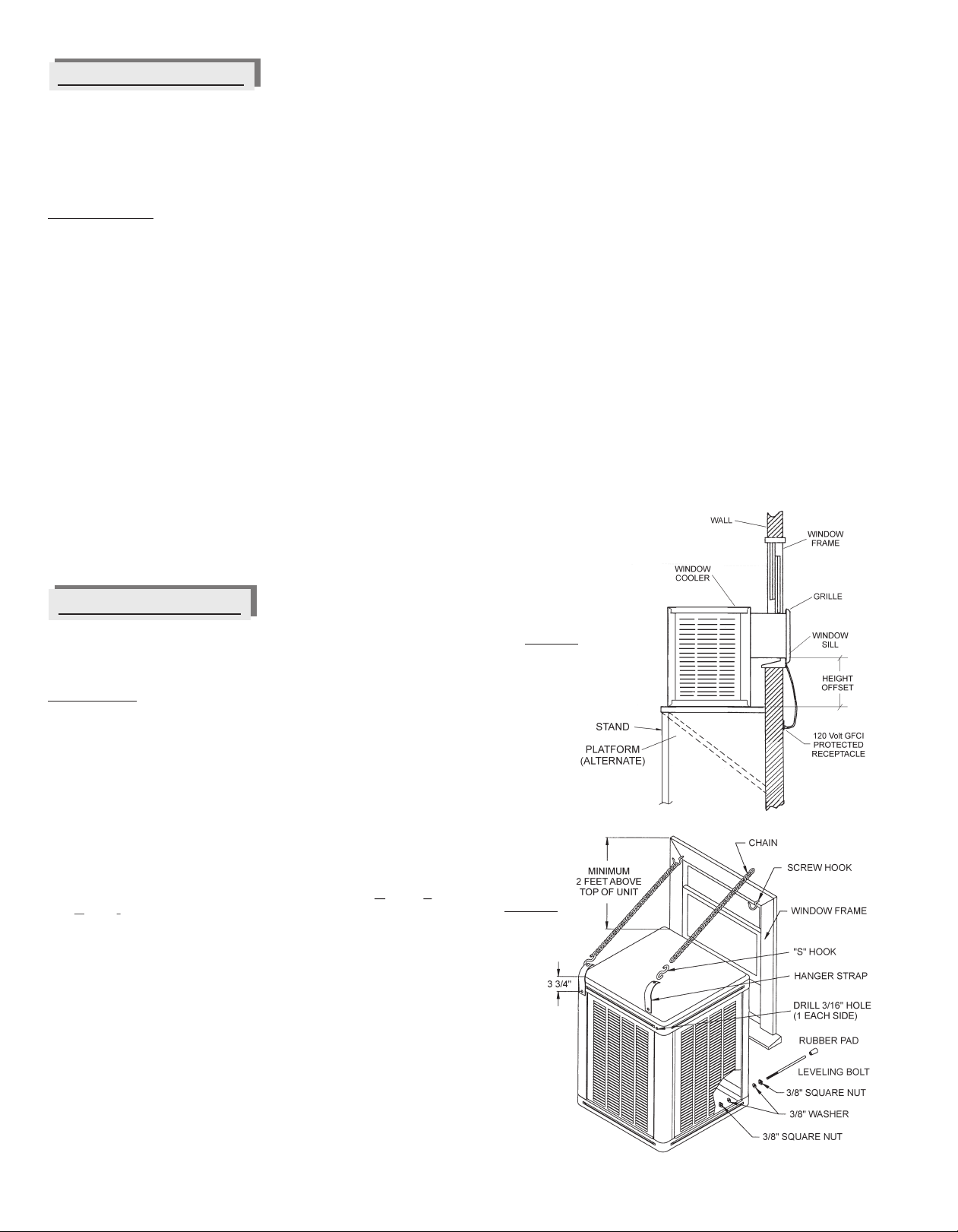
PMo t radl en r d r anive ; ve taa yuctos s ll do
PEdclae e o e m tega , g o
lcorón vijast c rr ctaen ui do se ursy
ua d l rof er e
pe ig.
tr m , ra, lvu dt o ec. snPMoo,bo ba d en je vá lael flo ad r, t etá
rr caneia d m t met cio a s
co e t me t
nstla asy co ple a n efunnle .
e a ament c c da,
PLínea d guasegureone ta
ae a g nt lebi rt , sinfu as
oab s.
PFl arast o a p o iot do ju adlr pio n vel.
e
n
ebbil
e ae
i
hy
da
P
Imp let dela om a g ra ibr y su v . Saud
r e la btdim l t se li e e
emuvacu iera el pe ene(véa “ mpi za d la
o a rvse la r a n
b mb”) y e i otció .
Pe ú se e s o il s d la b a e , p e mp lsa
As g re qulo trn loe tur in , je ol a i u da
y sp so s e la p le típt d
lo o re re d oa mo r z
estén a re aos.
PP le t iz l e b a li a eb n sió
o a mo r / po ea d tur in a ne minto ie ; ten n
r a e aarb a ga li e n e
cor ect n
la b nd , tu in irbr me t .
Cqu e ez
he eo de mpi o
RE AUC :
P C IONNuncperenid in filo
aolau ad s los tr(s)
y e l ire.
Etoultra n on óne/o la
r jilla dea s resa í e cdici d
sobepodí dal tor.r carga y r a ñar e mo
ave f r h qo l n t la n l efiao n c m n
P ra riica y c e ue de a i s a ció de n r d r e el o ie zo
icia u l, ae sig ie r d nin l oan a sig l u ntepoce imie to.
Ha á la sa a / t lan n n p r s, )
Pbrslid s ven i cio es(ve taas,ue taetc.
Pnfl c r ó l a e
eet lo d r .
E chu eeo dn
cavij n
el r c p acu e pa ed
PVefu o a eel il r jar o .
ri iq e si la bmbmp zó y os f t osse mo n pa ej s
Preo e u o .
Obse v c mi nza y f ncina
ncaso de oblas en o dep , r ias a l
Epr emalgunestos asos efére la ista de
tazando l pág6.
rfal as en ina
st icc g ete
Lia de nspeión
del
abin
D u eco nin l unen p c o s p r iesp és d l miezo icia y d ra t ise ci ne e iód cas,
r or e lo u n efé sel l r n a aevise ubse vsig ie t : Re i ra a aistataza do f ll s enla
á ine q se r .
pga6 si s ue e n cesa io
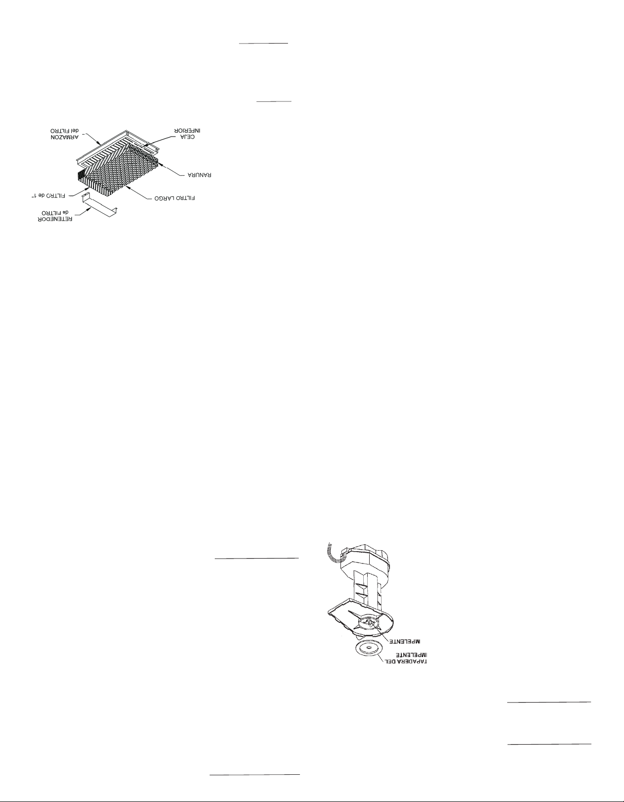
Pad s a d g , i r g i te t
Fug s e
la líne s eaua
fltos, ab ne, e c.
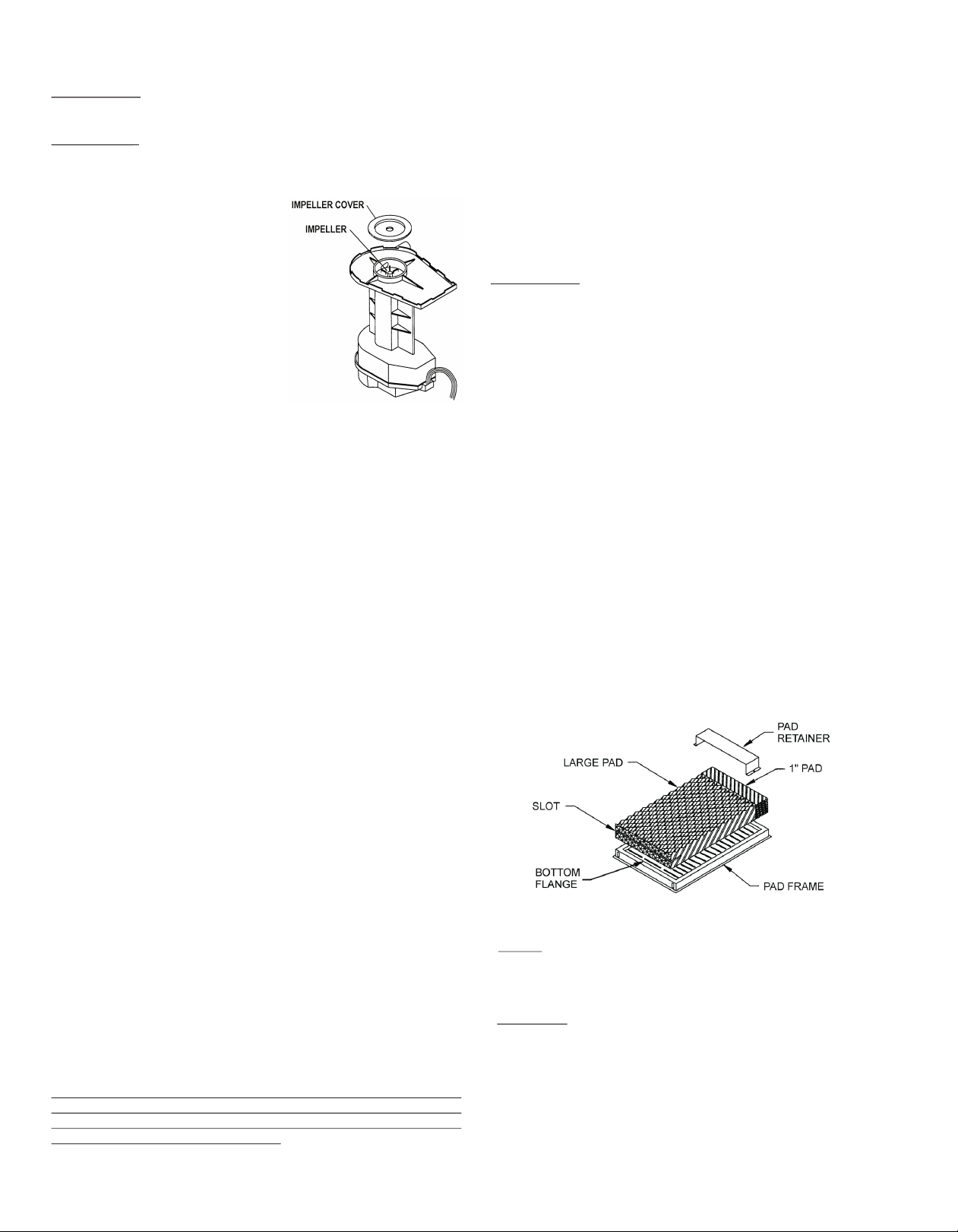
PFilr l e a rsmon pa enr s c s.t osde nfri do : e je r jos, o á ea se a
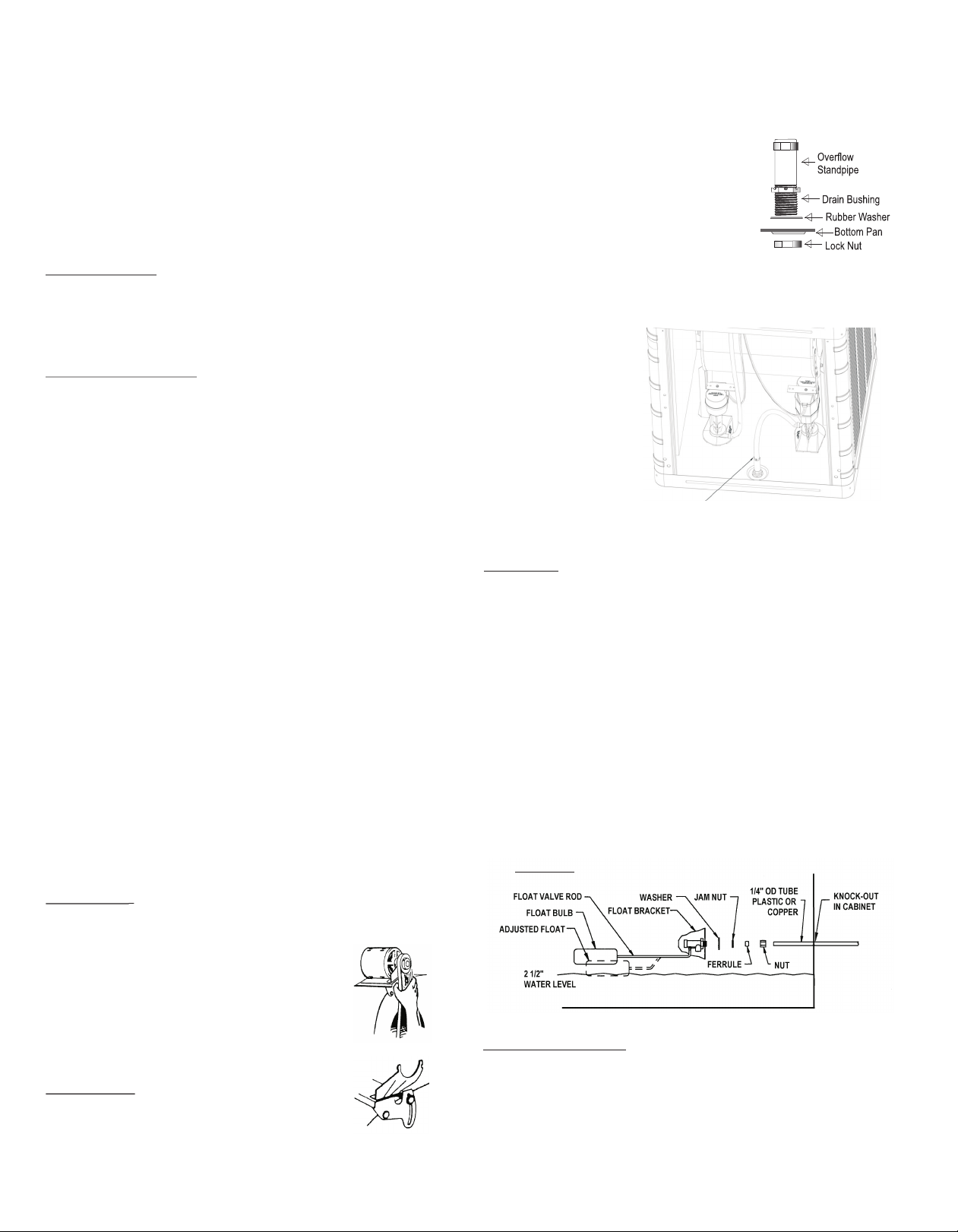
Pla s evl d g
sa o re oE ju te d l
ni eel a ua e
c r ct .
PVe f q lf u e aaolpa j n e
ri i ue e l jo d gu cmp eto y re oe l
sist mi r u i .
e a
dedst ib c ón
Pu in mi n l re n n is xta s.T rb a / otor gra ib mete, oru doe r ño
PCdn d b d tn/ in a n o
on icióe la an a / e siónalemie t .
Peinarl m t rll l g i t ,
Rv se la mo t du a de otor, o ni os de ab ne e
n o o e o ee s o a latu in pt otor ill spr s r s n la plesy derb a a re ad s.
LIT D
E
ATNM
INOSA MNEI ET
Ma t niet reul r e insp ccions prió ica on la c ave e un
ne im noga e e e dssl d
bu no ro on adose v ciodsu Aeoco l ef ia or. Elnfri do
eyp l g rie r o n rde a r
eb rebir ervicio ompl tameno u a ve por año ymás
decis ce o s nz
se uios l s co di ine lo requren am ientpolvo uso
g d i a nc o s ie ( b e ,
cons ant , cal ad d l gua, e c.) a a áxim ef ene
teidea t P r m a ici cia d
en r aminto ar a vda y paren , ca a do me s d ra te
fie, l g i ai cia ds se u n su
pera i n, l enrad r deeser inseciona o ympi do.o cóef i o b p c d lia
NOA: No ponerle braadepós tde a ua
Te l i o g
El deói o dsu en r ad r tne u acbado connuestro Pe la XT
p s te f i oie n a b r
cab d tipoa tfct.Ean d ro qu la b eano se egrá alfnd .
aaore a o s t u erp a oo
Lapa se esp gará y se so ar , t pando la b mb y el distri ui orca d e lt áa oabd
d gu.ea a
NOA
T:N use mpdore pa aenfria o es, án do tra am en o
o li iasrdr o s, t i t su
toaditivo uímico ne e n r dorE uso e a itivos oo r q e st e f ia. l d d
trataenos ra l agautoq e n sasa gr do nularlamit pa e u o r u o e n aaá
gra t ay pe ju icar a vida d l enrad r.
a n í r dál ef i o
nte de ce r la racón dea enimi nto, le
Asom nza ope i m nt ea
t l amnte todaslas i struc i nesemant nime o yde a l da e ncod e i nt
ope ción erv odaslae auci s y adverte i s
ray obs e t s pr c one nca.
impia
Lez
PRECAUCIO:Na ve su nfr adorn m ngue a
Nunclaeico a r
de j n; El aguauede ñar el m rla bomo en arardí p daoto y ba tr
alcon cto. M rsdaña spor el agu O los cu
du otoedo a Nbrela
r ntía.
ga a
Maeria es xt añ s, sar o,dpó t s dsa min ra es t beet le r or e si o e l, el e c. De n d
re overs e la re illasd osi os, fondo y o ros mpne t s. El
m e d s j e l f ltr ,t co o n e
cab dodra er e e fria or se pu de pone co o n nd cióna a u d o d su nderm e co i
de nu vo usa do aua tib a y unt ap ave
engi r o su
NOTA: Evit estro jo , estro jo oboch s ea amb e, estos
e pa s pa s r a d l r
da ar n él a ba o estimulano la co ro n.
ñácadd r sió
Manteniento Insp ciónim e ec
IM ORTANT:
PEAntese opl en ia r al cienzo
d erarefr do om
cadmporade enfriaento, os ej del
de a teadmigire l es a
tu bi,emoto , la mba on mapara aegurarser nalr boclanos
quegiren br mente Eln hac podíarsultar enun
li e .o erlo r e
motor emad
qu o.
In pecció pri dica de su n r dr ue e ealzar la v da lib e e
sne ó ef ia o pdrird
p ob ema e e e Pra áximeficie ciacadadosese d rante
rls dst . a m a n , msu
su ope ació , o n ualqie osón qu h br e enfiadr, o eb
rn e c ur ca i e aál r o lde
nsp cc onrlgna su er ncias
ieia .A usg e:
P¿Revi epor g t ra d s ios, gab e e etc.
so e s e lo f ltr int , ?
Pncu n r un os se s nla paja cua d n opercón
¿Ee t aptcoe noea i ?
P¿E cue tra losto nil os, u rca y t rn lo
n n r l te s o il s
op eso esap etads?
r r ro
Poidos exrñsn lachumace aso moore ?¿S n t a o e srt s
P¿L t rb a g ra li re en ea u ini b m t ?
P¿Flo ad r alco re o nvel?
t o rct i
Plagua d l de ósi o l pia?
¿E e p t im
P¿Co d n d a ba d / tens ón al ne mie to?
n ició e l n a i /i a n
jtetenóndea ba a
Aus silnd
Cad vez que in eccio e su nfri do , se a gu a d resr l
asp ne a r se r e vi aa
e sió de b nd enlesam le de mot r / t rb na Res la
tnn la aae n b o ui . vi e
co di ine
a an a s tiee esg st
u otro de ec os evise la
n c ó d l bdi nd a e sf t . R
al ne ción d la polea im ulsa a n a ol aotríz ( éase ag a 3i a e p dcol p e m vp in
parsos n má d ta les)a pa co s
el
.

Aj stde banau e d
PRECAUC O :
INDescon c e todala corri nte eléccae tetri
h c a l enfriad r y aseg rese que laband n este danda i e o ú a o o
vuetas a te e a ustar l tensión.
l n sdja
Te s ó deaand y ali eacióncorreca esmor an e,
nin l ban t i p t t
propia insta ación redu e cos mode nergíayl c n u e
extiendlaida ela ban a y lael motor.
ev d d d
PRECAUCION:Nunaoperea nidad silo fitro(s)c l u n s l
y/o larejilade aire.Esresult ría en con ición de
l to ad
sorecarga yporía dñarel motor.
b d a
Reise lav
tenión e labanda ap etándola.na t nsi n apopada
sd r U e ór i
permitiráuna de leión de ½ a ¾ epulga a.Para
f x d d
aumentar o reducirla tensión e a banda,afloje eld l
tornillo e la r nura de lamonad rael mot r.Ajustln at u d o ea
ban a aunatensión apropiada yapieteel tornillo.d r
dor v v ana - aunal U o CidEnfria Eaporati o de Vent M de s y u ado3
e aBuj deDren je
aleAr nde a de hul
Fondo
Tuerca
Tubo de
R bos oe ader
nsle bu e e re j y re os d roI ta j dd na e bae
nsta e l bd r b d e e nd d l en a or
Il e uje eeosa ero n lfo o efri d:
D sl la r d l dh l e e uje
eice a aneaeuen l b .
I r l je ene
ag j rel on o,ynse te e bulu e o d f d
ar
eau ca
pit
el ter .
Ar i e e tue r bde o d l stito n ll l bo d e osa r e p á co
jy a él l eram n ( preta
albu e pri teoig e te a do
o la ao) pa a r ve gac n m n r p e nirfu s.
octe aí a d a d d e je
C ne a un lne a ecu da e r na
coVC/ m n ea jar í je( bre / P agu r de d n) albu
e e aje caelag a ed dr n . Nun dren e u en l
cho ine a eeml n o dño a
te; m r l ssacu u aa s l
chp d o r ir.te oueen cu r
N:O
TA
nee a ua acue s gos oca es pl erí .
Dre l g de rdo conlo códi l l de om a
Coe te e mitro e Agan c
l Suin s d u
PR A C
ECUION:Tdslssa
aioee oeoa a i
ntlc nsdplmría
ti ne e c ir on loódo d dia y rea
d
en qu umplcs c ig s e e fic r gl se
s g da ,ll vd s c b poe on l om e n
euri d yea a a a orp rs a c p te te
sl
aeteo mn.
NO AT : os e r oes n de eneaaisteadg
Lnf iad r ose b con ctr s m s e a ua
“lan a”. gb ada ce e acorr e ce a aectiva eb d Aua l nal r la osión y r du lvidef d
los f ltr s y gai e . C n e e suinistrd g a e fr o co oi ob n te o ectlmo e a ualn iad r m
sigu :e
La vá vu a d n stro
de a ua pdr a i stlars n u itio
l l e sumi i g o í n a e e n
s
co n ee, paa
pe m bri ce r rpa a d sr o onve i ntr r itir ar y r a r ar evici
a gao d n en . U ub n u í o d /4se d e upa d e i viro n to co n m nim e1 ” eb sar
paae sum i ga ia en ia r,U ub á g a e
r lin stro
de a uahc le fr do nto m s r nd
seebusasil dist n a s re 1 0 p e ucida 1/
d e ra a ci e mayod 0 ies y r da 4”
la na a aun dd.en e trdde l i a
Ila d lflota r enl r zadr p o da
nstaleválvula edo aab a e a rveí .
Con c et o el sumi ide ga f o o Poaae t un ub d n stro a ua l l tad r. ng l
e ca d m r si ny laf u bre e e eo l tu, inse te
tur e co p eó ér la solxtr m de bo r
ltu al l p i te l ercpe ó be.
ebo en l vávua y a r é lo a tuade comrsi n i n
Mon ado Usado uegode Cadena
tJ
La instalaciónalernativa enulve elsituar la u i adnunave tana
t v e nde n
apropaa y sndo el jueg de cade a inclido para q e soporte elpesoi d u a o n u
de e friad r.si como montado n plataforma o arima, cadantalaciónl n oAe t i s
esifre te.os requerimientos exactos para montar y sellar l enfri dor
de n L e a
encotra ellima será det rmnado po elsitio yal momento de l
n dc e i r a
instalación. Lamayoría de lasinstlacion s requiern elcerrarlapart
a e e e
sinu o alreded rdel ducto, u otrasmodificacionesa cuadro delas o l
ventana quizás sean necesarias. Vea ilustracióFig. ) parainstl c ónn (2a a i
típica.Recuerde queelumb ald laven ana tiene que s r u iciente
r e t esf
fuerte ara soportarelpe o del e friad r aproximadament 25 libras).
psn
o
(e
0
Eueg dCad na C ntiene:l Joeeo
2 - Gancho Roscado 2 - Gancho “S”
s s s
2 - Torni losNivelad re 2 - Cojinese Hule
los d
4-Torni los Cuadradode 3 8”4 -Aad las de3/8”
ls / r e
- Len üeta parSuspender-#1024 x 1/2”largoo nillo
2g a2- Tr s
- #1024 Tuercas - Ca enase 5Pies Largo
2-2 d d
nstalación Jueo e a en:
I g d Cd a
Atornille ostornillos degancho roscados e el marco de la v ntnal n e a
aproxi ente dosp es arribdee friad r.Asegurese d ato nilla los a
m i a l noerr
lmáimo para mejor soporte.o x
Cooque unacadenacada ganh.l ac o
Fijelaslengüetasen l s perforaciones de 4.7 mmdeiametroa 5 d
proveidas n l pa te d atrásy arriba d lapiernas de en riado
e a r e e sl f r
usando los to nil o 10-24tuercas proveidas.stale lo ganch s “S
r l s y Inso”
enlaslen uetas.
g
nstale lostornillosniveldoresatraveselosagujeros11mm deI a d
iametro en la arte de bajo y enfrentedelenfrador. Usela tuerca y
d p ai
ra delaen la partedearuera inst le o coji es dehile encada n f a l s n a
rn llo nivelador. Lat era y la ar nde a sobrantes van en e t rn lltoiuc a l l o i o
dentro d lgabine e.
e t
Sitú elenfri dordetal man ra que el d cto descan e n elmarco dee a e us e
la eta a y las cejasd la rej llaesté dentrodel armaó de la
vn n e i nz n
ven an , er i ie dola abazad ra enforma deZ” oa izada deb jot ap m t n re“l c l a
d la parrilla,decanse enelmbralde lavnt na y to eentro delae u e a p d
ceja del umb alde la ventana Co ectelosganchos roscadosa l s
r . n o
eslabones de l cade a austando a unap sición ivelad .a njon a
Use lostornillosnivelad res e la ierna pra anivelar el enf iador cono d p a r
la ared. jute lost rnill s y la c dena para ivelare enfri dor.
pA s o o aanla
NTA: Posiblem nte stengaueea ivelar el nfr a or para
Oe e q r n e i d
compensar elpeso a regadoporlgua. Apietelastu rcas en lo
g e a r e s
tornillos nivelad re entro d l gabinete.o s d e
Cierrela ventanapar queescanse sobre la par e supeiorelductoa d t rd
(en ventanas que cuelgane ticalente)oventanas que se deslizan
vr m
allado delducto (ventanas qu se deslizan hacia l s lados). Bloq ee
e o u
la erurarestate delaventana con unmateralapropiado para ea b t n i l
caso (plexiglás, hojasólida deplástic , pael ó ido d adea, e c. .o n s l e mrt)
Será necesario sel ar u lquier unión alrededor delducto aral c a p
pr v nirla e trada delluvia, polo tierra, insectos, et . ua quie
ee n a l v / c C l r
sllad re b ena clida o inta serv ríapara e propósito.
e o d u a d c il
C ÓOPERA IN
tro sConle
n r oe i se e o rloLos i te rupt r s se ut lizan paral cci na e mod de operación
tt o adel enfriador. Esos interrup ores contr l nla velocidad de la turbina -
l ( a L e r e oA taOn)/Apagado(Off)/Baj ( ow) y la operaciónd enf iami nt
o On / ff
(bomba)
-Encendid ( ) Apagado(O).
Figura 3
n l
ap a r eneel t bald erd mitI sertee da t dod
dre aj ne
uo vertic e dsboaen o
e
como se mu stra

i E eso i
2Enfr adorvaporativo de Ventana -Maunal d U yCu dado
INTRODUCCIÓN
Su eniador fue detalladamentepro ado e inspeccio ado antes de
fr b n
salirde lafábrica. Ester manualesuna gua de p ocedimientos para
í r
una nstalac ón propia juntocon información deun c idado azonble
i i u r a
y mantenimientoqueleasegurará un enfriamiento euro,
s g
económico y sinproblemas. El no seguir estainstrucciones puede
s
dañar su enfriador, incapacitar su operación, crear unpotencial para
una seria lastimadura personal y/oanular la garantía.
Lea cuidadosamente
Ntasp raSalidasdeAire/ Enfriamiento Máximoo a
Esto
se controla con que tantoseabran la vent nas y puertas.
s a
INSTALACION
Cuidadosamen e lealoscontenidos de este manual y revise los
t
planosdel enfriador paraqueusted se familiarizecon las varias
partes antes decomenzar el procesode instalacn.
ió
PRECAUCION:Desconecte toda l corrie teeléctrica
a n
delen riador antes deintentarinstalar, abrir, o darle
f
servicio a su enfriador.
Aún cuando r tinari mente se i speccione odeservicio al interior, el
uan
nfriador puede empezar accidentalmente. Mant nga todo elpe sonal
ee r
alejado del enfriador y suministrode orrienteal trabajar en él. Antes de
c
darle servicioo lipiar lau idad, desenchufe la unidaddel receptáculo de
mn
la pared y as guresequeelcordónoseaenchuf doe nuevo yele n a d
enfriadorprenda accidentalmente. No enchufeel cordón en el
receptáculo hastaque lainstalación otrabajo de servicio esté completo.
Antes deint ntainstalar el enfriador,asegúrese quel s
er a
siguientes preparacionesse hayan echo
h :
Instale e friadores en un ventana donde solamente a refrescode
ni
afuera entredeenfriamiento. Eiteel ins alar las unidades en áreasv t
que restringe el movimiento libredel aire alrededor y la entradadel
n
enfriador, ocerca de tubos de venteo, extractores d cocina, etc ; ya
e .
querepugnantes olor s o vaporespueden ser induc dos por la
e i
unidad.
Asegúreseque lasuperf ciede soporte es lo suicientefuerte parai f
soportaelpeso delefriador cuando estéen uso. Esta unidad pesará
r n
proxi adamente 250libracua do opere en plena capacidad.
am s n
Verif que que la superficie de soporteesté nivelada entoda
is
direcc ones.
i
Ya quelos enfriadores funcionan mej rcuando el escape de aire eso
en abundancia, usted puededejar puertas o ventanas abiertas para
que sucasapueda respirr. Paraobtener la capacidad máxima de su
a
enfriador,y ayudar a mantener insectos, polvo, tierr , etc fuera del
a
espacio enfriador,lacasadebe mantenerse ligeramente a una
presión pos tiva (aireentrando la casa sea más que el que sale)i
¿Quet nto debe habrir susventans o puertas? Debe habrirsus
aa
abertushasta que elairedetro de la casacasi se balance conel
ran
aire deafuera. Unmetodo usado para determin r si el aireestaa
razonablemente eselde ponerun pe azo depapelen contradel
d
alambre mosquitero de laventaa más lejana alenfriador yajustar
n
laabrturade las ventanas hasta que e papelsequede
e l
lijeramenteen elalambremosquitero e la ventanaUsted pueded .
ajustar di erentesventanas en lacasa paradirigir másflujo de aire
f
alas areas que estén c padas durante diferentestiempos del díao u
olanoche (ejemplo: ven anas de la sala durante el día,de la
t
recámara durante lanoche)
NOTA: Paraliminar el torrente de aire cal ente alponer a
e i
funcionar el enfriador, s gurese de encender labombaunosa e
minutosantespara humedecerlos iltros de ponera funcionarla
f
turbina.
Esteenfriadortiene que ser enchufadoa una fuente de 120 vo tios con
l
receptáculo protegido con GFCIInterrupt r de Circuito a Faltade
(o
Tierra). Siusted n estáeguro ielreceptáculotieneproteccióno s s
GFCI, consulte con unelectricista competente. Estereceptáculo
debe estar stuado entre unadistancia de 5 pies dela abertura de la
i
ventana. (Elc rdóndesuministro esde6 pies delargo,el uso de una
o
extensión no es recomendable).
M ntdoen plata orma ot rima
oa f a
La insalación malmente env ve elsituala unidad e una
tnor uel r n
vent na apropiada y laons uc ión de una plat ma o t i a ar
a c tr cafor ar m p a
que soportee pesodel enfriador.Ya cad nsta ac ón
l que a i l i es
d ferelrequer mi tos ex tos para m ntaysel ar el enfrador
i nte, os i en acorli
en contrdcli a s rádetermi ado r el s tio l momentoa
ael m e n po iy a de l
ins alac ón. La a oría l instal iones requieren ecerr lt im y de as ac lar a
p te s n uso al ededor de duct , u otras m ifica i sal c ode
ar i r l o od c one uadr
aantana izás s n ne es i . Vea i us ac ón (Fig. ar
lv qu ea car as l tr i1) pa
italaci íp c C tr a l p at forma o ar ma debajo a
ns ón t i a. onsuy a l a t i de l
ent na, l uficiente fuerara sot el sod enfr ador
va o s tep por ar pe el i
(apr ximadamente 250 i ras .o l b )
Mida cons uyaapl afor a velas teque pmita
y trun at m ni da oupor er
la s rfiie inio del to del enfriador c nsar sobre el
upe c ferrduc des a
umbral de v ana. P mita pacioparal c ión del drenaj /
ent er es aonex e
tub de reb ader
o os o.
Si elfirdeal m nera q l to descee lmar o
túe en r ado t a ue educ ans n ec
de la entana as ceja la r jil a tén dentro del ar azón la
vyl sde e l es m de
ventNO clave s oto n s a ravés d lfodo y la
ana. clavo r illote n
supef en que se a m ntar, o anula laar ntía.
r icieva o est g a
er elav tana para que des anse obr laar superior del
Cir en c s e p te
ducto (en entanas que c lgan er c lmente) o v tan que e
v ue v ti a en as s
lizan al l o del duc v ana que edesl z n hac a os
des ad to ( ent ssiai l
ldos)Bl ee la turarest de lav ana coun i
a . oqu aber ante ent n mater al
opi do p ael c o ( exiglás hoja ólidapláti o, panel
apr a ar as pl ,s de s c
sido mader etc . Ser necesa ioslrualqui un ón
ól de a, .) á r el ac eri
ror el duc para prevenirla e ada la ll i ,al eded dto ntrde uv a
polvo/tierr ins tos etc.alqu er slador de uena alida o
a, ec , Cu i el b c d
intaeriía para propós to.
cs v r el i
Figura1
Figu a 2
r

RIR APO T VO d VENTANA
ENF ADOEV RA I
e
opee lmo od laub n condispoitior nsis o i a o p r
No r etre t r i a s v st a t r z d s aa
ot
o
l
a
lae c
dd
cnr r vloia.
No pee lan d d s
efir(s) /o
la ejillade a r , e to u de c u ao r ui a in l lt o y r i esp e a s r
ue elsob ecar ueel o o yd ña loq rg m t r a r.
OTA:N
Ninstl e n adorc rca e extcto s ou o e n laióya uoae l
efri e dr
are tbs
d v
et
icnqe
oo s
oapo
r
e
spee se nu ds
en
l uia.
lre v udn ridc
io a n
dd
El us de n d s, adi osquí co o t tam ent s n esauidad a u a
o áoo tiv mi s
ra i o e t n nln
la garant .ía
Su a n a nocu rea o de vío Rporte ualq i r dñde en o deg ra tí b d ñ s e n . ecu e a o ví
in edia a d st b i oa t n port d rre l za d l e trega.
m toli ri u dro lra sa o a i n o a n
Pa fuura refe n an teelmo e o ú erod ri , fea y ugar de
ra t reci , a o d l ,n m e se e ch l
omra e e friador epra i o:
cpd su nvao t v
dl #
:
Moe
o
Serie:
#
Fc
h do r
a
eaeCmp :
Lugard Comp:e ra
ie cor ónde alimen c n es d ñado este de e s r r e p za o orS l d ta ió a be e m la d p
un c dns ecia o e sambe disponble pr pa te d l fab i a u
or ó e pln l i o re r c nte o s
ge te s r i io
a n de e v c .
ÍAPTGU DELPRO IE ARO
ND
E
MA UALUSO
YCUIDADO
9-2 /1-99254 Date:0316
Seg d
uri ad
ntc
I s ala ión
o
Inci
e c
Op raión
n e t
Ma t nimien o
T z d s
ra anoFalla
LEAY ONS VE ESTAS
CER
INST UCION
R C ES
IMPO TAN E DESEGURIDAD
R T
e i i e d ae c a p d t u r rr d t s o e l
Flic tac on s: Ustecaba dompr r unrouc o de s pe io en imien oy di eñ ,qu a
d á m s viud s p pm n i tad o r o m nn
ar el ejor er ic oc an o ea ro ia ete ns la o, pe ady a te ido.
u e e a p pcle ta s s l o nmc n c a
Esteman al fu dis ñado praro or ionar a us ed y uin ta ad r la i for a ió ne es ria
p a o a p a in cam n n y n r u u r llnufr.
arm nt r,o er r spec ionr, a teer enco tra c alq ie fa a e s enriado
r e e i e Ina o ep i rs lar L c ó
Lapim rascc ón dst lacióneInici , s
es ec almentepaael in ta do .a
se cin
ea M n i toct i tr cn e p a ó y m n i topal
sgund , atenim en, on iene ns uc io es d o er ci n atenim enar e
oe i n s e e ió e c n b inu in r a ó blpr pi tar o, mie traqu la s cc n d Detec ió de Pro lemas cl ye fom ci n so reos
pbm s a ero le am scomun s.
N AL F voda e a u a p o r
IST ADOR:a r e
entreg rst
g íal r pieta io.
DRECA AR IEI D
AVETNI - P A REDUC R L R ESGO E INCENDIO,
SGA L T CALTMDE O , SE O IE
DE CAR E ÉC RI O AS I A URASAP RSNAS OBERV L S GUINTE:
ea estas instrucc ne cui adosament antes d intala ,opear o da
L ios d e e s r r r
s rvicio a a
uni ad.e l d
st enfriadorde e ser o ect do a un fuente e 12 Vc a.60 c los
E e b c na ad 0 .ic
slame t . N T o a imp opanu arálaaran ía de motor y o la
on e O A: v lt je r iol g tl /
bomb y pod í cauasers last adu as prsonales o d ñosaa r asria im r e ala
pr piead.o d
Est nfriaor
deb e nchu ado a u ecep ácul rot gid oe e d e s re f n r t o p eo c n
GFC , uehido p opi menteintala o con todos c digos loa es
Iq a sr a sd s lo ócl
y n c ona sSi n tienseg rid d que el r cptáculo no est
a i le . o e u a e e á
prt gid con GFCconsultéc n n lect icist compet nte.
o e o I o u e r a e
Est enfriador v ne e uipdo con u corón con con uct r ycavija de ieq a n d d o le
terrpaa equ o. Notrated anlar l dis o itoe seg rid d
i a r l e ipe u eps iv d u a
r movien o c v ade t rr .e d lalaij ie a
No srecom nda el uso de extensione e c r ae ies lé t ics
Nolo ope e s l co dón o la lavija e tán añ dose c alq ier o ma.
ri e r c s d an u u f r
S l u idad e tá añad o unci na mal, nc ntinue opeán ola
i a n sd a f o o or d .
Sie pre d s oect lacorr ente elé trica dela unid d antesd
m e c n e i c a e
tab jar oars rvicoa u enrado .
r a d leei s f i r
Algno mo elotienen nres rtor o o ifico enla ngera du s d s u t iccnr ma u e
ag a ue asegura el lu ode agua propioa a el f tro. N remove luq fj
pr il
o r o!
emuv el c rdón de re etáculo elétric ja ndo e clavijo l
R e ao l c pcola dla a yn e
crdn
.
oó
HOENIXMANUFACTURING,INC.
P
od l:WCW40
M e B 00
Conseracióndel gua
v A
Enfriadorvapoativo
Er
Table of contents
Other Aerocool Air Conditioner manuals
Popular Air Conditioner manuals by other brands

mundoclima
mundoclima CL23420 installation manual

Retro Aire
Retro Aire R40C Installation, operation & maintenance manual

SPT
SPT WA-1511S user manual

Frigidaire
Frigidaire FFRE0533S1E0 Use & care guide

Mitsubishi Electric
Mitsubishi Electric PLA-M100EA installation manual

Mitsubishi Electric
Mitsubishi Electric MSZ-DM25VA operating instructions

Gree
Gree GKHD(12)ABND3A2AI Service manual

Mitsubishi Electric
Mitsubishi Electric Mr. Slim PUZ-M200YKA2.UK Service manual

EcoNet
EcoNet A2024AJVCA installation instructions

York
York YNKFZC024-055BAADAFX owner's manual

Mitsubishi Electric
Mitsubishi Electric NTXFKs15a112a Series manual

Samsung
Samsung AQV12NSA Service manual