Aerodyne Beechcraft Baron G58 User manual
1
2
TABLE OF CONTENTS
Additionalitemsrequired…………….
Adhesivesandbuildingsupplies…..
Optionalsuppliesandtools………….
Wingassembly…………………………….
Installingthelandinggear…………..
Fixedgearinstallation…………………
Nosegearinstallation………….........
Retractablelandinggear……………..
Mainlandinggeardoors……………..
Nosegeardoors………………………….
Empennageassembly…………………
Installingtheelectronics…………….
Wingattachment………………………..
Motorinstallation……………...........
Nitroengineinstallation………………
Nacelleinstallation………………………
Doorsandinteriorinstallation……
CGandFlyingcharacteristics………
1
1
1
2
5
5
6
6
7
8
9
11
11
13
14
14
15
16
Introduction:
From all of us at RC aerodyne thank you
for your purchase of our Beechcraft G58
Baron. This is one of our finest models
that we have developed and produced.
The aircraft is made up of composite
fiber and balsa wood construction. The
ARF comes fully detailed in every
aspect and is sure to bring the owner
much joy in building and flying this
aircraft. So from all of us here at RC
aerodyne, enjoy your Beechraft G58
Baron.
Additional items required
(2) 2 ½ inch spinners
(2) 11x8 3 bladed props (or)
12x6 2 bladed props
(6) 50 oz/in servos 2-flaps, 2-ailerons
1-elevator, 1-rudder
(1) 35 oz/in servo for the retracts
(optional)
(2) 45 oz/in servos for throttle (if using
nitro engines)
(2) .32-.46 electric motors or
equivalent. Or .32-.46 nitro
engines.
(2) 60-75 amp ESC ( if using electric
motors)
(1) external BEC or receiver battery
(M) Miscellaneous servo extensions,
switches, 12ga. wire, and connectors
(2) 5 Cell 4000mah lipo batteries
Adhesives and building supplies
-1 oz bottle of Med CA
-1/2 oz bottle of Slow cure CA
-5 min epoxy
-Canopy glue
-CA accelerator
-CA applicator tips
-Hobby iron
-Rotary tool
-Marker pen
-Razor blade knife
-Petroleum jelly

3
WING ASSEMBLY
1. Remove the flap from the main wing
and remove the wooden dowels and place
them aside.
2. Locate the 4 metal hinges from the parts
bag and insert them into the pre-drilled hole
in the wing.
3. Locate the aileron bell-crank from the
aircraft parts and insert the rod through
the main wing and through the holes in the
flap hinges . It may be necessary to
move the flap back and forth to get the
aileron rod to slide through. After the rod is
in place lightly pull on the hinges to ensure
that the rod has passed through the hinges.
4. Insert the flap and ensure that there is
smooth movement of the flap surface. After
you are satisfied with the placement remove
the flap and apply epoxy to the hinges and
replace the flap into the wing. After the
epoxy is dry pull lightly on the flap to
ensure proper fitting.

4
5. Cut out the covering on the top and
bottom surface of the wing as shown here.
Press down lightly on the center of the
cutout area to get a defined line to cut.
Ensure that you have a sharp razor blade to
give you a clean cut.
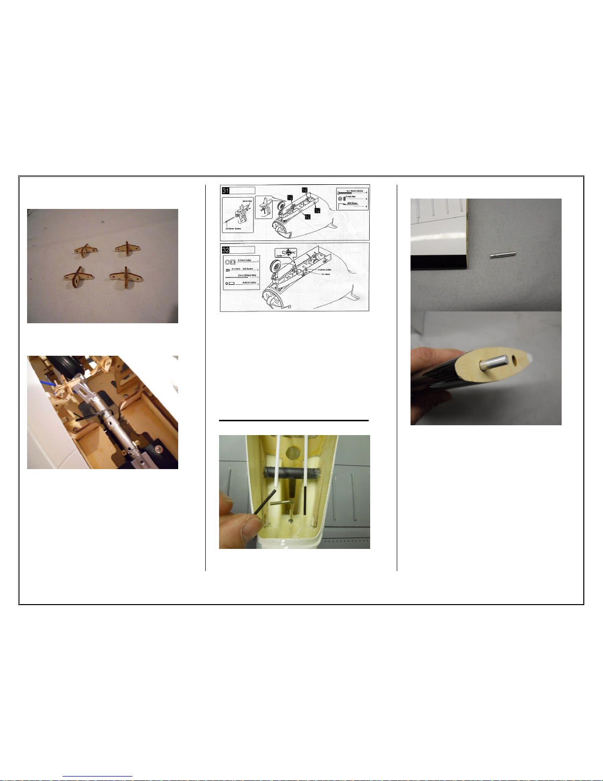
6. Assemble the collar as shown above and
place on the aileron bell-crank. Secure the
collar to the bell-crank from both the upper
hole with the 3x25mm screw and the bottom
hole with the 3mm set screw. Attach the
control connector to the flap control rod.
7. Detach the aileron from the wing and
remove the dowels from the hinge holes.
8. Insert the nylon pipe hinges into the
aileron. Cut 2 ridges off 4 pipe hinges for
the 2 outboard hinges on either aileron.
After satisfied with the placement of the

5
hinges remove the hinges from the aileron
and apply epoxy to the hinges and allow
drying. Check to ensure proper fitting.
9. Apply epoxy to the tip of each hinge.
Apply petroleum jelly to the pivoting part of
the hinge to allow the epoxy to move around
the hinge. Insert the aileron to the wing and
allow drying. After dry, apply light tension
to the aileron to ensure a secure fit.
10. Locate 2 out of the 4 wing guides.
Using 5 min epoxy, glue the wing guides
into place on the trailing edge of the outer
wings. Leave ½ in of the guide protruding
from the wing. Let sit and allow to dry.
11. Locate the wing locks and using 5 min
epoxy glue them into place on the outer
wings. Ensure that the cut out portion of the
wing lock is facing the bottom of the wing.
12. Glue in the 4 plastic rings into the 4
holes on the top side of the wing.
INSTALLING THE
LANDING GEAR
13. Using a razor blades cut out the
landing gear holes in the bottom of the
plane. (If using the fixed gear do not cut out
the black portion of the picture).

6
FIXED GEAR
INSTALLATION
14. Insert the main landing gear into the
landing gear blocks.
15. Epoxy the landing gear blocks into
place.
16. Locate the landing gear cover spacer
and put in place. There is no need to glue
the spacer.
17. Screw the landing gear cover in place.
NOSE GEAR INSTALLATION
18. Assemble the nose gear as shown in
the diagrams above. Epoxy the nose gear
plate to the nose gear block. Secure the
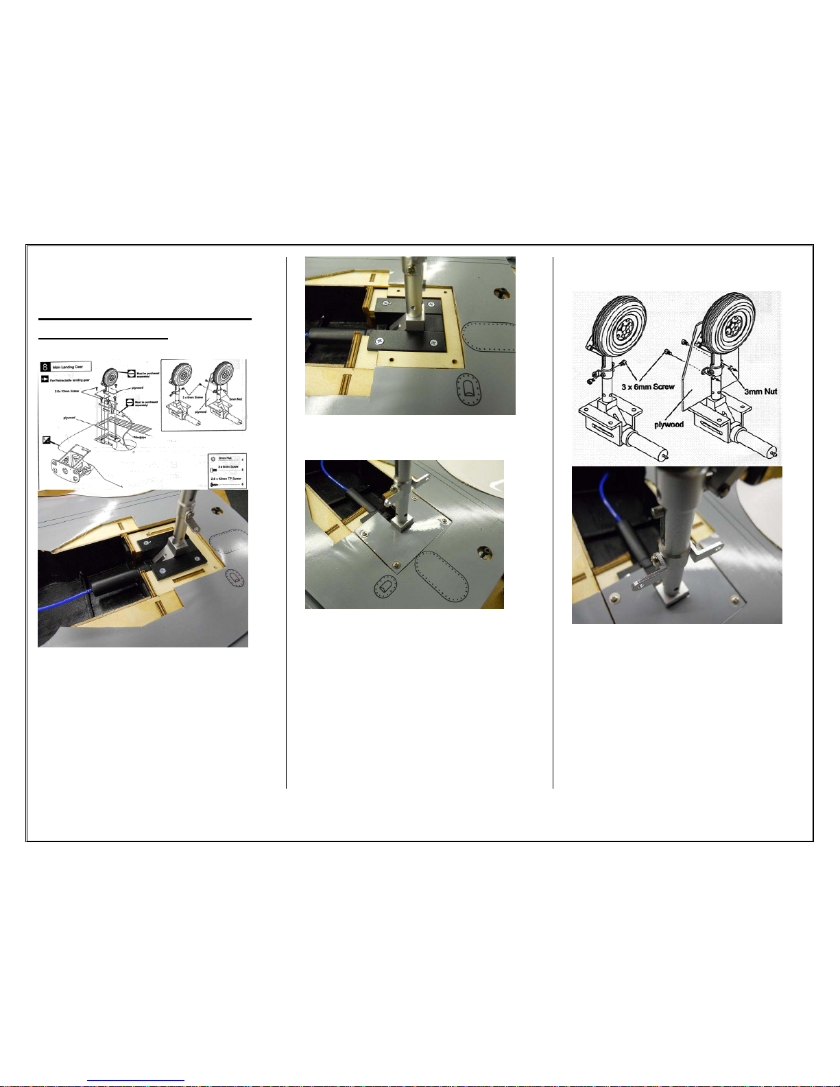
7
nose gear to the fuselage using the 4 screws
as shown above.
RETRACTABLE LANDING
INSTALLATION
19. Install the main landing gear using the
2.6x12mm screws.
20. Place the landing gear cover spacer
into place. There is no need to glue down.
21. Place the landing gear cover into place
and using 2.6x12mm screws to secure into
place.
LANDING GEAR DOORS
22. Attach the gear door mounts to the
landing gear.
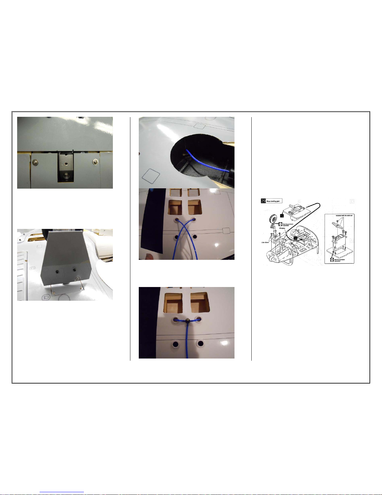
8
23. Manually close the landing gear and
hold down with your hand. Place the
landing gear door in place on the wing and
make a mark on the landing gear for where
the door needs to mount.
24. Place the landing gear door in the
proper place and mark the holes for the door
mounts. Drill a hole and place the bolt and
nut in place to mount the door.
25. Route the airline through the punch-
out hole and through the access holes in the
wing.
26. Attach the airline “T” to the 2 airlines
from each landing gear. Ensure that there is
no “kinking” of the airline at the access
holes. Leave plenty of slack in the hose.
27. Install the nose gear into place using
the 2.6x12mm screws. Attach the hose line
and route the line along the outer side of the
fuselage. Install the rudder servo and glue
the bracket into place using epoxy.
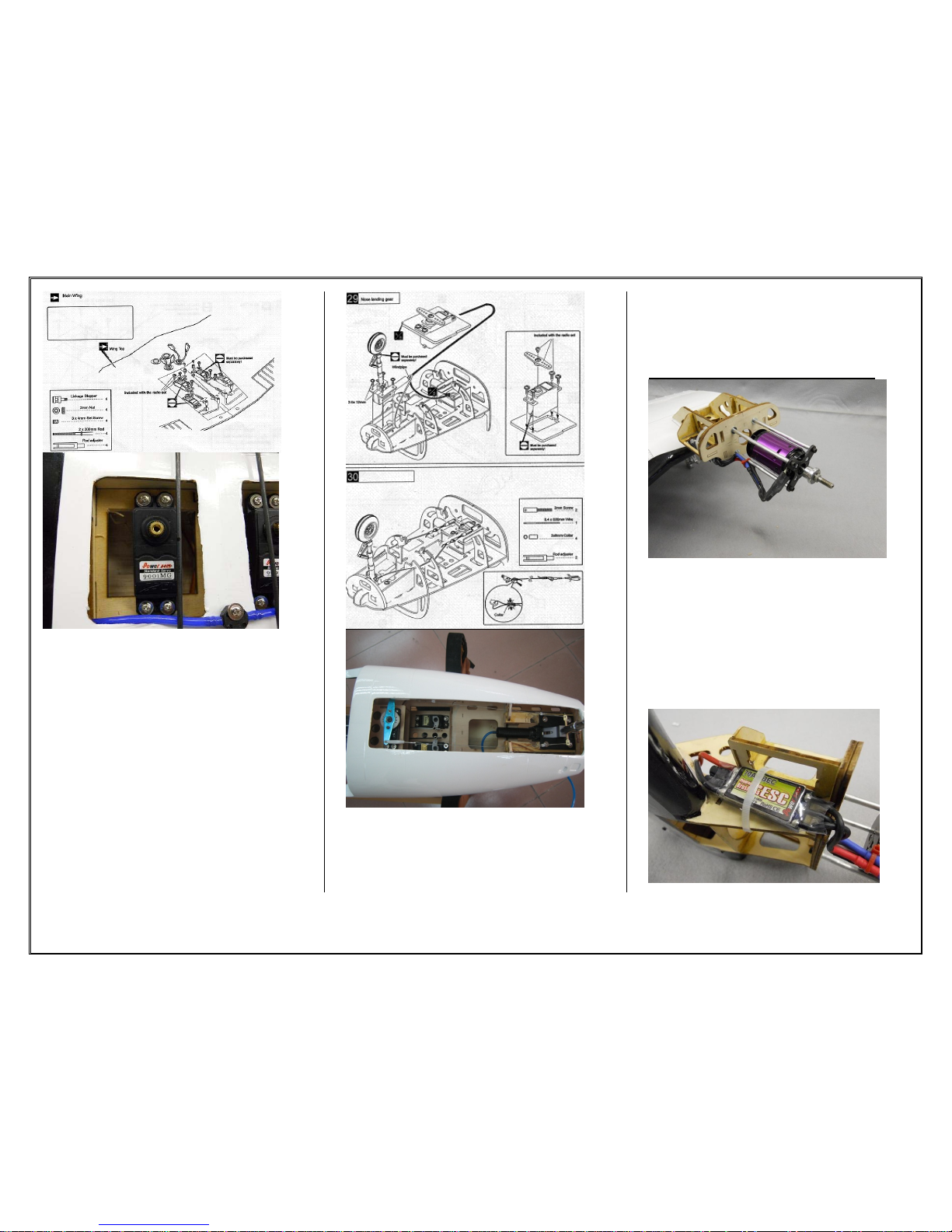
9
NOSE GEAR DOORS
28. Assemble the nose gear door hinges
using CA.
29. Use a twist tie to lock the nose landing
gear in the up position to assemble the gear
doors.
30. Attach the landing gear doors as
shown using the hinges provided. Use CA
to tac glue the hinges to the doors. Open
and close the doors to ensure proper fit and
function. After satisfied glue the hinges into
place with epoxy. Use the wire and collar as
shown to close the landing gear doors when
the gear is up.
EMPANNAGE ASSEMBLY
31. Insert the threaded rod into each of the
control rods for the tail section.
32. Locate the final 2 wing guides and
glue them into place on the horizontal
stabilizers. Use epoxy to glue into place for
a secure bond.
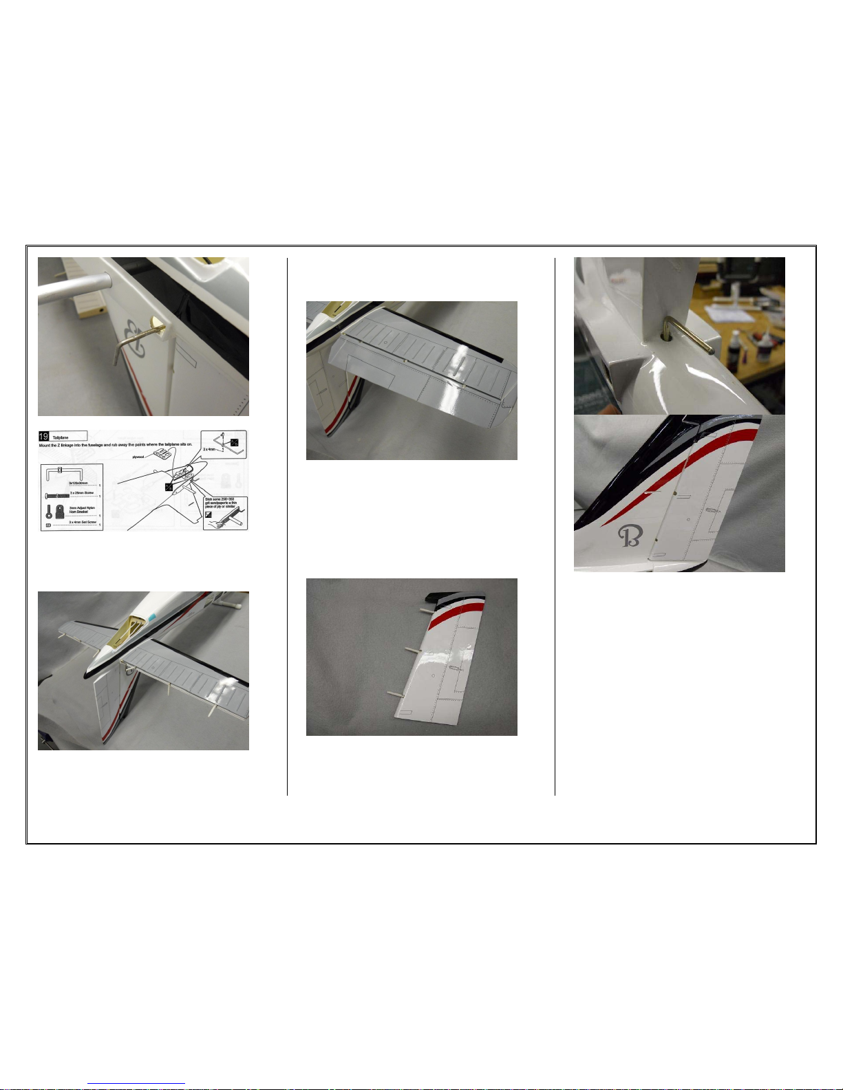
10
33. Insert the elevator control connector
into place along with the horizontal
stabilizer pipe.
34. Epoxy the horizontal stabilizers and
the elevator hinges into place. Use tape to
ensure the gap between the horizontal
stabilizer and fuselage is tight. Let the
epoxy dry before moving on to the next step.
35. Glue the elevators into place using
epoxy and ensure that there is smooth
movement of the elevator before the glue
cures. Use petroleum jelly on the pivoting
part of the hinge to ensure you don’t lock up
the hinge.
36. Insert the rudder control horn into the
slot in the fuselage. Glue the rudder hinges
into the rudder. Use epoxy to glue the
hinges to the rudder and the to the vertical
stabilizer.
11
37. Assemble the ball link and quick
connect to the control rods. Assemble the
control link to the elevator and rudder
control rods.
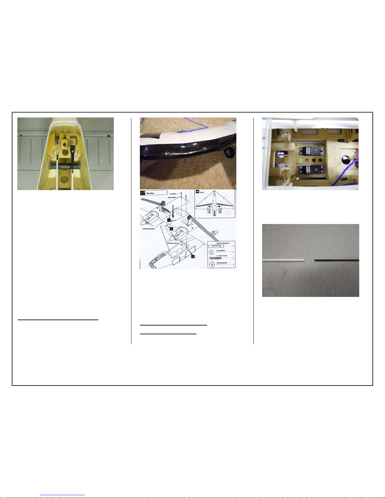
WING ATTACHMENT
38. Center the wing onto the fuselage and
mark the 2 holes in the leading edge of the
wing. Using a ¼ inch drill bit drill the holes
out and place 2 ¼ inch dowels into the
holes. Leave ½ inch of the dowel protruding
from the wing.
INSTALLING THE
ELECTRONICS
39. Install the rudder and elevator servo
into the servo bay on the fuselage. Mount
with the servo head towards the front of the
fuselage.
40. Disconnect the control links from the
control horns and pull out the push rods out
from their sleeves. Attach a threaded rod
into the nylon pushrod and cut to proper
length. Insert the rod back into place and
attach to the servo horn.
12
41. Insert the flap and aileron servos into
the servo bay on the wing. Use the threaded
pushrods and link the servos to their control
horns. Mark and cut the control rods to the
proper length needed.
42. Install the nose gear steering servo and
slide into servo bay. Glue the servo tray into
place using epoxy and let dry. Use the wire
and the connectors supplied to attach the
servo to the nose gear. Attach the wire to
the nose gear and make sure that the wire is
tight. When satisfies crimp the wire tight
and cut off the excess.
MOTOR INSTALLATION
43. Cut and tap 8 aluminum 3/16 pipes and
tap with a 6/32 tap. For a Hacker type
motor the pipes are 98mm long but the
distance may vary depending on the motors
used. Place the motor mount against the fire
wall and center the motor mount on the hole.
Mark and drill all 4 holes for each side. Bolt
the pipes into place and install the motor.
13
44. Install the ESC on the side of the
firewall and route the wires to the center of
the wing.
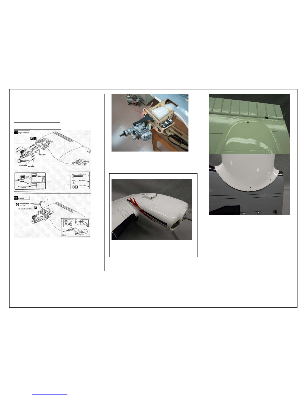
NITRO ENGINE
INSTALLATION
45. Install the engine mounts using the
proper spacers for your motor. You may
need to trial fit the engine mount to
determine the proper spacing. Install the
fuel tank and route all necessary fuel lines
into place on the engines.
46. Install the throttle servo and route the
servo wire toward the center of the wing.
NACELLE INSTALLATION
47. Install the nacelles on each wing.
Ensure that the motor shaft is centered on
the nacelle center hole.
48. Drill one hole on the top of the nacelle
and 2 on the bottom and use the 2.6x12mm
wood screws to mount the nacelle to the
wing.

14
49. Drill 1 hole on either side of the
nacelle cover and using the 2.6x12mm
screws secure into place.
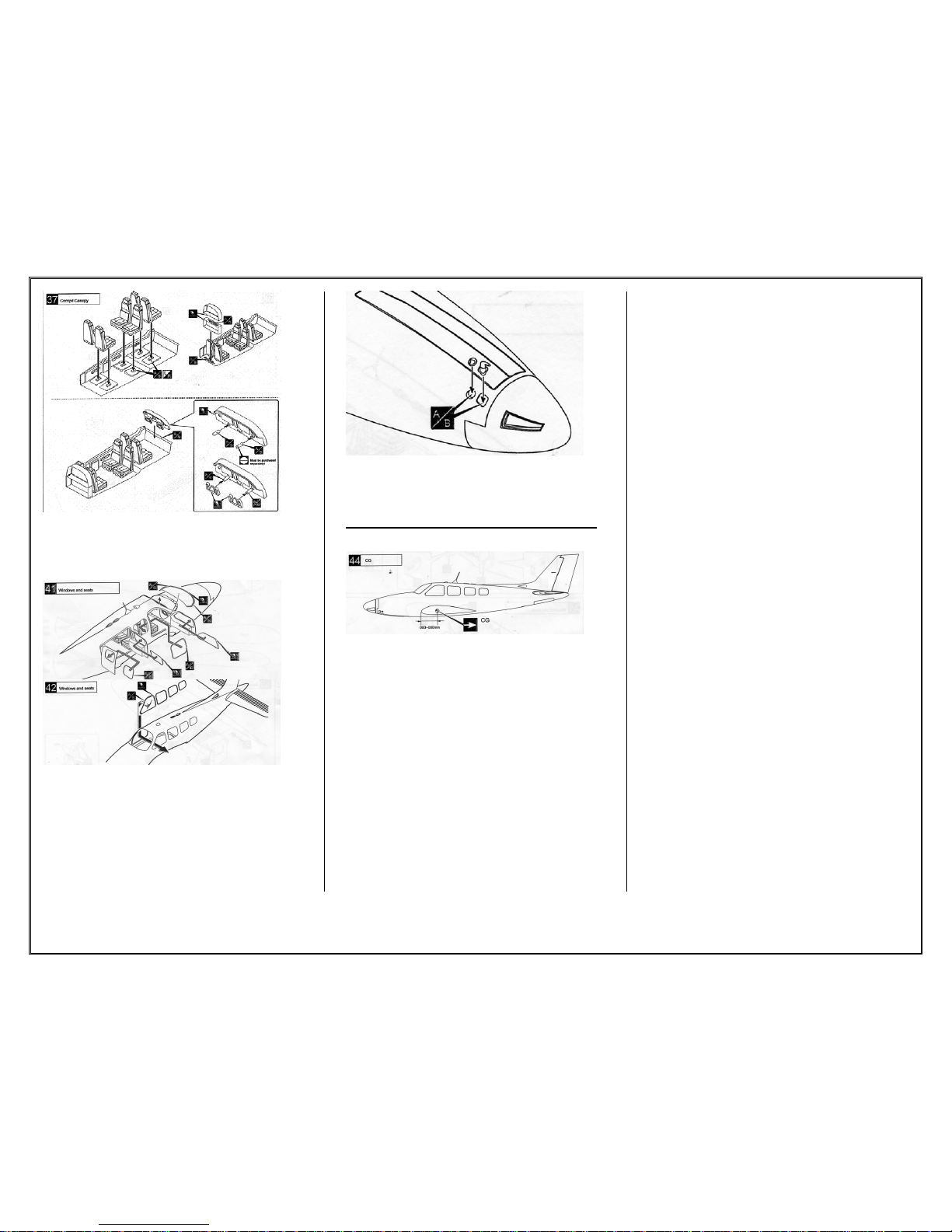
DOORS AND INTERIOR
INSTALLATION
50. Install the upper and lower interior kit.
Assemble the seats and paint as desired.
51. Assemble the hinges for the doors and
install the rear and front doors.
15
52. Install the interior pieces to the
cockpit. Paint as desired. Use med CA for
assembly.
53. Assemble the windows into place and
glue in using canopy glue.
54. Install the final scale details to the
fuselage.
CG and Flying characteristics
The CG location is 3 .25 inch from the
leading edge of the wing.
Wind direction
Pilots prefer to take off and land facing
into the wind. This has the effect of
reducing aircraft speed over ground and
hence reducing the distance required to
perform either maneuver.
Runway orientation is determined from
historical data of the prevailing winds in
the area. This is especially important for
single-runway airports that don't have
the option of a second runway pointed in
an alternative direction. Almost all
runways are reversible, and aircraft use
whichever runway in whichever
direction is best suited to the wind. In
light and variable wind conditions, the
direction of the runway in use might
change several times during the day.
Takeoff:
On takeoff allow the plane track straight
down the runway and get the speed up
on the airplane. The airplane will almost
lift itself off the runway. If not apply a
small amount of up elevator and climb
out at a steady shallow angle. Do not
force the plane up if it is not ready.
Make sure you have the proper length
runway for take-off.
Flying:
The plane is very stable throughout
flight. All throughout slow and fast
flight the plane remains in positive
control and is very easy to handle.
16
Landing:
It is very important to always have
power thru the entire landing procedure.
NEVER CUT THE THROTTLE ON
LANDING!!
This is typical for twins. They do not fly
well with power shut off, especially on
final approach. If you are unfamiliar
with flying twins, they will loose air
speed quickly without proper throttle
management.
* Tip:
If landing is not your strong point, try
thinking of a low pass. For beginners,
landing such a large plane can be a bit
intimidating at first.
After take-off quickly trim the plane,
and immediately set up for
some approaches. Get a feel for how
much room on final you need to give
yourself. Make some low and slow
passes. When landing always keep
power on. Think of your landing as just
another low and slow pass.
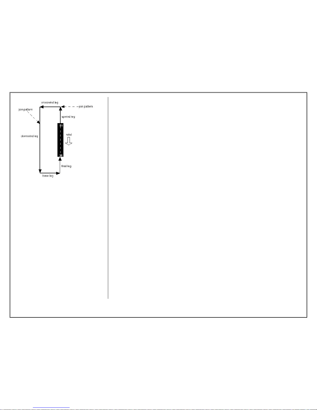
If you are unfamiliar with flying a
typical pattern, please refer to diagram
above. This will help with your
approaches.
When turning base to final, it is very hard to
see the speed of your aircraft due to the
orientation of your location and
the position the aircraft is pointed in. Its
critical to make sure you have enough
speed on final until you are able to see
the aircraft at a better angle.
These are the recommended control surface
throws:
High Rate / Low Rate
ELEVATOR
3/4" up 1/2" up
3/4" down 1/2" down
RUDDER
1-1/4" right 3/4" right
1" left 1/2" left
AILERONS:
3/4" up 1/2" up
1/2" down 1/4" down
FLAPS: 1-1/4" down
Table of contents
Other Aerodyne Toy manuals


