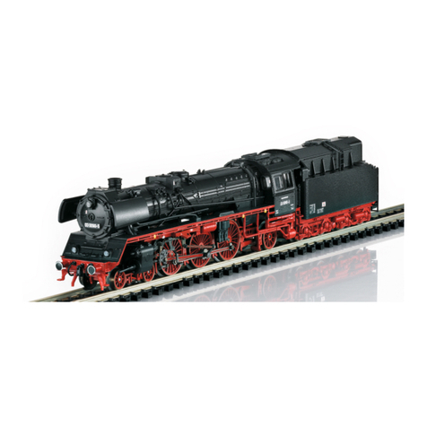
Trix BR 221 User manual

Modell der Diesellokomotive BR 221
16202
D GB USA F

2

3
Inhaltsverzeichnis: Seite
Informationen zum Vorbild 4
Sicherheitshinweise 6
Wichtige Hinweise 6
Funktionen 6
Hinweise zum Digitalbetrieb 6
Schaltbare Funktionen 7
Configurations Variablen (CVs) 8
Wartung und Instandhaltung 18
Ersatzteile 22
Table of Contents: Page
Information about the prototype 5
Safety Notes 10
Important Notes 10
Functions 10
Notes on digital operation 10
Controllable Functions 11
Configuration Variables (CVs) 12
Service and maintenance 18
Spare Parts 22
Sommaire : Page
Informations concernant le modèle réelle 5
Remarques importantes sur la sécurité 14
Information importante 14
Fonctionnement 14
Remarques relatives au fonctionement en mode digital 14
Fonctions commutables 15
Variables de configuration (CVs) 16
Entretien et maintien 18
Pièces de rechange 22

4
Informationen zum Vorbild
Ausgehend von den fünf Prototypen der V 200 (1968 umben-
annt in BR 220), die ab 1953 erprobt wurden, begann ab 1956
die Ablieferung der ersten 50 Serienmaschinen dieser Die-
sellokomotiven an die Deutsche Bundesbahn (DB). Geliefert
wurden diese Lokomotiven von den Firmen ATLASMaK und
Krauss-Maffei.
Die V 200 war von zwei V-12-Dieselmotoren angetrieben, die
austauschbar von MAN, Maybach (MTU) oder Daimler-Benz
(MTU) geliefert wurden. Mit Abgas-Turbolader leistete jeder
Motor 1.100 PS, bei der Nachfolge-Baureihe 221 (ab 1962)
sogar 1.350 PS. Diese riesigen Triebwerke mit 64,5 l und 78,2
l Hubraum wurden mit elektrischen Anlassern von je 13,5 kW
(später 20,3 kW) Leistung gestartet. Zuvor wurde mit einer
Elektro-Pumpe automatisch der erforderliche Motoröl-Druck
aufgebaut (Vorschmierung). Die Verbindung zum jeweiligen
Drehgestell-Antrieb stellte ein hydraulischer Drehmoment-
Wandler her, der unmittelbar vor dem Anfahren mit Öl gefüllt
wurde.
Die letzten 220 er wurden 1984 aus dem Dienst der DB
genommen, die 221 erst vier Jahre später. Mehrere ins
Ausland verkaufte Maschinen sowie einige deutsche
Museums-Loks sind heute noch zu sehen.

5
Information about the prototype
V 200 In 1956 the series production of the first 50 units
of the class V 200 diesel locomotive (redesignated class
220 starting in 1968) was begun, which derived from the
5 prototypes that had been tested starting in 1953. These
locomotives were built by the companies ATLAS-MaK and
Krauss-Maffei.
The V 200 was powered by two V-12 diesel motors that were
delivered by MAN, Maybach (MTU) or Daimler-Benz (MTU).
With an exhaust gas torbocharger, each motor provided
1,100 horsepower, even 1,350 horsepower with the class 221
successor series (starting in 1962). These immense power
plants with 64.5 liter (approx. 3,936 cubic inches) and
78.2 liter (approx. 4,772 cubic inches) piston displacement
each had electric starters rated for 13.5 kilowatts (later
20.3 kilowatts). An electric pump would automatically build
up the required motor oil pressure (advance lubrication). A
hydraulic torque converter, that was filled with oil directly
before the locomotive was started, produced the connection
to the running gear for each truck.
The last class 220 units were taken out of service by the
DB in 1984, the class 221 units four years later. Several
locomotives sold abroad as well as several German museum
locomotives can still be seen today.
Informations concernant le modèle réel
L a livrasion des 50 premiéres locomotives diesel V 200
(rebaptisées BR 200 à partir de 1968) a débuté en 1956, sur
la base des 5 prototypes, qui furent mis à l‘épreuve à partir
de 1953. Ces locomotives ont été livrées par les sociétés
ATLAS-MaK et Krauss-Maffei. La motorisation de la V 200 se
composait de deux moteurs Diesel V-12 livtés selon les cas
par MAN, Maybach (MTU) ou Daimler-Benz (MTU).
Grâce au turbo-compresseur, chaque moteur développait
1 100 ch, et même 1 350 ch pour la série suivante 221 (à par-
tir de 1962). Des démarreurs électriques de 13,5 kW chacun
(par la suite 20,3 kW) permettaient de lancer ces énormes
mécanismes moteurs de 64,5 l et 78,2 l de cylindrée. Aupa-
ravant, une électropompe établissait automatiquement la
pression d‘huile-moteur requise (prélubrification). La liason
evec chaque entraînement de bogie était assurée par un
convertisseur de couple hadraulique qui se remplissait
d‘huile juste avant le démarrage.
Les derniéres 220 furent retirées du service da la DB en
1984, ce n‘est que quatre ans plus tard que les 221 subirent
le même sort. Aujourd‘hui encore, il est possible de voir
plusieurs machines vendues à l‘étranger ainsi que quelques
locomotives allemandes de musée.

6
Sicherheitshinweise
• DieLokdarfnurmiteinemdafürbestimmtenBetriebssys-
tem eingesetzt werden.
• DieLokdarfnichtmitmehralseinerLeistungsquelle
versorgt werden.
• BeachtenSieunbedingtdieSicherheitshinweiseinder
Bedienungsanleitung zu Ihrem Betriebssystem.
• Analog14Volt=,digital22Volt~.
• FürdenkonventionellenBetriebderLokmussdas
Anschlussgleis entstört werden. Dazu ist das Entstörset
14972 zu verwenden. Für Digitalbetrieb ist das Entstörset
nicht geeignet.
• SetzenSiedasModellkeinerdirektenSonneneinstrah-
lung, starken Temperaturschwankungen oder hoher
Luftfeuchtigkeit aus.
• DasverwendeteGleisanschlusskabeldarfmaximal
2 Meter lang sein.
• ACHTUNG! Funktionsbedingte scharfe Kanten und Spitzen.
• VerbauteLED`sentsprechenderLaserklasse1nach
Norm EN 60825-1.
Wichtige Hinweise
• DieBedienungsanleitungunddieVerpackungsind
Bestandteile des Produktes und müssen deshalb aufbe-
wahrt sowie bei Weitergabe des Produktes mitgegeben
werden.
• FürReparaturenoderErsatzteilewendenSiesichbittean
Ihren Trix-Fachhändler.
• GewährleistungundGarantiegemäßderbeiliegenden
Garantieurkunde.
• Entsorgung:www.maerklin.com/en/imprint.html
Funktionen
• EingebauteElektronikzumwahlweisenBetriebmit
konventionellem Gleichstrom-Fahrgerät (max. ±12 Volt),
Trix Systems, Trix Selectrix (SX1) und Selectrix 2 (SX2)
oder Digitalsystemen nach NMRA-Norm.
• AutomatischeSystemerkennungzwischenDigital-und
Analog-Betrieb.
• KeineautomatischeSystemerkennungzwischenden
Digital-Systemen.
• Dreilicht-Spitzensignalvorne,zweiroteSchlusslichter
hinten, mit der Fahrtrichtung wechselnd.
Hinweise zum Digitalbetrieb
• BeimerstenBetriebineinemDigital-System(SX1,SX2
oder DCC) muss der Decoder auf dieses Digital-System
eingestellt werden. Dazu ist der Decoder einmal in
diesem Digitalsystem zu programmieren
(z.B. Adresse ändern).
• DerBetriebmitgegenpoligerGleichspannungimBrems-
abschnitt ist mit der werkseitigen Einstellung nicht mög-
lich. Ist diese Eigenschaft gewünscht, so muss auf den
konventionellen Gleichstrombetrieb verzichtet werden
(DCC:CV29/Bit2=0).

7
Schaltbare Funktionen
Spitzensignalfahrtrichtungsabhängig/Schlusslichtrot an F0
Geräusch:Signalhorn —F1
Geräusch:Betriebsgeräusch — — F2
Geräusch:Hornkurz — — F3
ABV, aus — — F4
Geräusch:Bremsenquietschenaus — — F5
Stirnbeleuchtung Führerstand 2 aus — — F0 + F6
Führerstandsbeleuchtung — — F7
Stirnbeleuchtung Führerstand 1 aus — — F0 + F8
Geräusch:Druckluftablassen — — F9
Geräusch:Schaffnerpff — — F10
Geräusch:Bahnhofsansage — — F11
Geräusch:Türenschließen — — F12
Geräusch:Bahnhofsansage — — F13
Geräusch:Kabinenfunk — — F14
Soundan/aus — — F15
2
7
1
6
STOP
PR
3
8
Sx
5
ON
Lz
4
9
1/2
Central-Control
66800 f0 - f3 f4 - f7

8
CV Bedeutung Wert DCC ab Werk
1 Adresse 1 – 127 3
2 Minimalgeschwindigkeit 0 – 15 15
3 Anfahrverzögerung 0 – 255 3
4 Bremsverzögerung 0 – 255 3
5 Maximalgeschwindigkeit 0 – 127 97
17 ErweiterteAdresse(obererTeil)(CV29,Bit5=1) 0 – 255 192
18 ErweiterteAdresse(untererTeil)(CV29,Bit5=1) 0 – 255 0
19 Traktionsadresse(0=inaktiv,Wert+128=inverseFahrtrichtung) 0 – 127 0
21 Traktions-Modus; Bit 0 – 7
=
^
F1 – F8 0 – 255 0
22 Traktions-Modus; Bit 0 – 1
=
^
FLf – FLr, Bit 2 – 5
=
^
F9 – F12 0 – 63 0
29
Bit0:UmpolungFahrtrichtung
Bit1:AnzahlFahrstufen14-28/126
Bit2:DCCBetriebmitBremsstrecke
DCC-, Selectrix- und Gleichstrombetrieb
Bit5:Adressumfang7Bit/14Bit
0 – 255 6

9
par Bedeutung Wert SX2 ab Werk
001 Adresse Einer- u. Zehner-Stelle 0 – 99 1
002 Adresse Hunderter- u. Tausender-Stelle 0 – 99 10
011 Anfahrverzögerung 0 – 255 3
012 Bremsverzögerung 0 – 255 3
013 Maximalgeschwindigkeit 0 – 127 97
014 Mindestgeschwindigkeit 0 – 15 15
018 Geschwindigkeit Rangiergang 0 – 127 97
021 Bremsabschnitte; 1 oder 2 0, 1 0
081 Dimmung Licht normal 0 – 31 31
082 Dimmung Licht alternativ 0 – 31 15
WerkseinstellungfürSX1:01-542,erweitert:00-274

10
• Thewarrantycardincludedwiththisproductspecies
the warranty conditions.
• Disposing:www.maerklin.com/en/imprint.html
Functions
• Built-inelectroniccircuitforoptionaloperationwith
a conventional DC train controller (max. ±12 volts),
Trix Systems, Trix Selectrix (SX1), and Selectrix 2 (SX2),
or digital systems adhering to the NMRA standards.
• Automaticsystemrecognitionbetweendigitalandanalog
operation.
• Noautomaticsystemrecognitionbetweenthedigital
systems.
• Tripleheadlightsinthefront,dualredmarkerlightsinthe
rear, that change over with the direction of travel.
Notes on digital operation
• Whenoperatinginadigitalsystemforthersttime(SX1,
SX2, or DCC), the decoder must be set to this digital sys-
tem. To do this, the decoder must be programmed once in
thisdigitalsystem(example:changetheaddress).
• Thesettingdoneatthefactorydoesnotpermitoperation
with opposite polarity DC power in the braking block.
If you want this characteristic, you must do without
conventionalDCpoweroperation(DCC:CV29/Bit2=0).
Safety Notes
• Thislocomotiveisonlytobeusedwiththeoperating
system it is designed for.
• Thislocomotivemustnotbesuppliedwithpowerfrom
more than one power pack.
• Paycloseattentiontothesafetynotesintheinstructions
for your operating system.
• Analog14voltsDC,digital22voltsAC.
• Thefeedertrackmustbeequippedtopreventinter-
ference with radio and television reception, when the
locomotive is to be run in conventional operation. The
14972 interference suppression set is to be used for this
purpose. The interference suppression set is not suitable
for digital operation.
• Donotexposethemodeltodirectsunlight,extreme
changes in temperature, or high humidity.
• Thewireusedforfeederconnectionstothetrackmaybe
amaximumof2meters/78incheslong.
• WARNING! Sharp edges and points required for operation.
• TheLEDsinthisitemcorrespondtoLaserClass1accor-
ding to Standard EN 60825-1.
Important Notes
• Theoperatinginstructionsandthepackagingareacom-
ponent part of the product and must therefore be kept as
well as transferred along with the product to others.
• PleaseseeyourauthorizedTrixdealerforrepairsor
spare parts.

11
Controllable Functions
Headlights/Redmarkerlight on F0
Soundeffect:Horn —F1
Soundeffect:Operatingsounds — — F2
Soundeffect:ShortHorn — — F3
ABV, off — — F4
Soundeffect:Squealingbrakesoff — — F5
Headlights at engineer´s cab 2 off — — F0 + F6
Engineer‘s cab lighting — — F7
Headlights at engineer´s cab 1 off — — F0 + F8
Soundeffect:Lettingoffair — — F9
Soundeffect:Conductorwhistle — — F10
Soundeffect:Stationannouncements — — F11
Soundeffect:Doorsbeingclosed — — F12
Soundeffect:Stationannouncements — — F13
Soundeffect:Cabradio — — F14
Soundon/off — — F15
2
7
1
6
STOP
PR
3
8
Sx
5
ON
Lz
4
9
1/2
Central-Control
66800 f0 - f3 f4 - f7

12
CV Discription DCC Value Factory
Setting
1 Address 1 – 127 3
2 Minimum Speed 0 – 15 15
3 Acceleration delay 0 – 255 3
4 Braking delay 0 – 255 3
5 Maximum speed 0 – 127 97
17 Extendetaddress(upperpart)(CV29,Bit5=1) 0 – 255 192
18 Extendetaddress(lowerpart)(CV29,Bit5=1) 0 – 255 0
19 Consistaddress(0=inactive,Value+128=inversedirection) 0 – 127 0
21 Motive Power Mode; Bit 0 – 7
=
^
F1 – F8 0 – 255 0
22 Motive Power Mode; Bit 0 – 1
=
^
FLf – FLr, Bit 2 – 5
=
^
F9 – F12 0 – 63 0
29
Bit0:Traveldirectionpolarityreversal
Bit1:numberofspeedlevels14–28/126
Bit2:DCCOperationwithbrakingBlock
DCC-, Selectrix and DC power operation
Bit5:addresssize7Bit/14Bit
0 – 255 6

13
par Discription SX2 Value Factory
Setting
001 Address for one and ten placeholder 0 – 99 1
002 Address for hundred and thousand placeholder 0 – 99 10
011 Acceleration delay 0 – 255 3
012 Braking delay 0 – 255 3
013 Maximum speed 0 – 127 97
014 Minimum speed 0 – 15 15
018 Speed for switching range 0 – 127 97
021 Braking section; 1 or 2 0, 1 0
081 Dimming of lights, normal 0 – 31 31
082 Dimming of lights, alternative 0 – 31 15
FactorysettingforSX1:01-542,advanced:00-274

14
Remarques importantes sur la sécurité
• Lalocomotivenepeutêtreutiliséequ‘aveclesystème
d‘exploitation indiqué.
• Lalocomotivenepeutêtrealimentéeencourantquepar
une seule source de courant.
• Veuillezimpérativementrespecterlesremarquessur
la sécurité décrites dans le mode d’emploi en ce qui
concerne le système d’exploitation.
• Analogique15volts=,digital22volts~.
• Pourl’exploitationdelalocomotiveenmodeconventi-
onnel, la voie de raccordement doit être déparasitée. A
cet effet, utiliser le set de déparasitage réf. 14972. Le set
de déparasitage ne convient pas pour l’exploitation en
mode numérique.
• Nepasexposerlemodèleàunensoleillementdirect,
à de fortes variations de température ou à un taux
d‘humidité important.
• Lecâblederaccordementàlavoieutilisénedoiten
aucun cas dépasser deux mètres.
• ATTENTION! Pointes et bords coupants lors du fonction-
nement du produit.
• LesDELinstalléescorrespondentàlaclasselaser1
selon la norme EN 60825-1.
Information importante
• Lanoticed‘utilisationetl’emballagefontpartieintégrante
du produit ; ils doivent donc être conservés et, le cas
échéant, transmis avec le produit.
• Pourtouteréparationouremplacementdepièces,
adressez vous à votre détaillant-spécialiste Trix.
• Garantielégaleetgarantiecontractuelleconformément
au certificat de garantie ci-joint.
• Elimination:www.maerklin.com/en/imprint.html
Fonctionnement
•
Module électronique intégré pour exploitation au choix avec
régulateur de marche conventionnel c.c. (max. ±12 volts),
Trix Systems, Trix Selectrix (SX1) et Selectrix 2 (SX2) ou
systèmes numériques conformes à la norme NMRA.
• Reconnaissanceautomatiquedusystèmeentreexploita-
tions numérique et analogique.
• Pasdereconnaissanceautomatiquedusystèmeentre
les systèmes numériques.
• Feuxdesignalisationtriplesàl‘avant,deuxfeuxrouges
de fin de convoi à l‘arrière avec inversion selon sens de
marche.
Remarques relatives au fonctionnement en mode digital
• Unepremièreexploitationensystèmenumérique
(SX1, SX2 ou DCC) exige un réglage correspondant du
décodeur. A cet effet, le décodeur doit être programmé
une fois dans ce système numérique (modification de
l’adresse par ex.).
•
L’exploitation avec courant continu de polarité inverse dans
les sections de freinage n’est pas possible avec le réglage
d’usine. Si cette propriété est désirée, il faut alors renoncer
à l’exploitation conventionnelle en courant continu
(DCC:CV29/Bit2=0).

15
Fonctions commutables
Fanaléclairage/Feudendeconvoirouge activé F0
Bruitage:trompe,signal —F1
Bruitage:Bruitd’exploitation — — F2
Bruitage:Trompecourt — — F3
ABV, désactivé — — F4
Bruitage:Grincementdefreinsdésactivé= — — F5
Fanal de la cabine de conduite 2 éteint — — F0 + F6
Eclairage de la cabine de conduite — — F7
Fanal de la cabine de conduite 1 éteint — — F0 + F8
Bruitage:Échappementdel‘aircomprimé — — F9
Bruitage:SifetContrôleur — — F10
Bruitage:Annonceengare — — F11
Bruitage:Fermeturedesportes — — F12
Bruitage:Annonceengare — — F13
Bruitage:Radiocabine — — F14
Activation/Désactivationduson — — F15
2
7
1
6
STOP
PR
3
8
Sx
5
ON
Lz
4
9
1/2
Central-Control
66800 f0 - f3 f4 - f7

16
CV Signification Valeur DCC Valeur Parm. Usine
1 Adresse 1 – 127 3
2 Vitesse min 0 – 15 15
3 Temporisation d‘accélération 0 – 255 3
4 Temporisation de freinage 0 – 255 3
5 Vitesse maximale 0 – 127 97
17 Adresseétendue(partiesupérieure)(CV29,Bit5=1) 0 – 255 192
18 Adresseétendue(partieinférieure)(CV29,Bit5=1) 0 – 255 0
19 Adressepourlatraction(0=inactif,Valeur+128=directioninverse) 0 – 127 0
21 Mode traction, bit 0 à 7
=
^
F1 à F8 0 – 255 0
22 Mode traction; bit 0 à 1
=
^
FLf à FLr, Bit 2 à 5
=
^
F9 à F12 0 – 63 0
29
Bit0:inversiondepolarité,sensdemarche
Bit1:Nombredecransdemarche14–28/126
Bit2:ExploitationDCCaveczonedefreinage.
DCC-, Selectrix et courant continu
Bit5:tailled‘adresse7Bits/14Bits
0 – 255 6

17
par Signification Valeur SX2 Valeur Parm. Usine
001 Adresse unités et décimales 0 – 99 1
002 Adresse centaines et milliers 0 – 99 10
011 Temporisation d’accélération 0 – 255 3
012 Temporisation de freinage 0 – 255 3
013 Vitesse maximale 0 – 127 97
014 Vitesse minimale 0 – 15 15
018 Vitesse de manoeuvre 0 – 127 97
021 Sections de freinage, 1 ou 2 0, 1 0
081 Variation lumière normale 0 – 31 31
082 Variation lumière alternative 0 – 31 15
Paramètresd’usinepourSX1:01à542,étendus:00à274

18
MINITRIX
66623

19
66626Märklin
7149
7149
O
I
L
40h

20
1
2
3
4
1
2
3
4
This manual suits for next models
1
Table of contents
Languages:
Other Trix Toy manuals

Trix
Trix B VI User manual

Trix
Trix MINITRIX 14938 User manual

Trix
Trix Adlers User manual

Trix
Trix H0 BR 96 User manual

Trix
Trix EG 507 User manual

Trix
Trix Ae 3/6II User manual

Trix
Trix MINITRIX 16661 User manual

Trix
Trix H0 BR 39.0-2 User manual

Trix
Trix Ce 6/8III Series User manual

Trix
Trix Minitrix Reihe 1016 / BR182 User manual