Aerola PHANTOM User manual

1
RIGID WING GLIDER
PHANTOM
MANUAL
Kiev, Ukraine
2005

2
TABLE OF CONTENTE
ection 1.
General information
1.1. Introduction
1.2. Main data
1.3. Operation limitations
1.4. Flying tests
ection 2.
et up procedure
ection 3.
Preflight inspection of the glider
ection 4.
Performance and flight characteristics
ection 5
Breakdown
ection 6.
Maintenance

3
ection 1. GENERAL INFORMATION
1.1. Introduction
The Phantom rigid wing is an advanced product of Aeros Ltd and Aerola Ltd.
It is aimed at improvement of modern competitive glider with very high
performance combined with maximum safety and comfort.
Please read and be sure you thoroughly understand this manual before
flying your Phantom. Be sure you are thoroughly familiar with the setup,
breakdown, preflight inspection and maintenance procedures as described in
this manual.
In case of any doubts or questions contact your local dealer or Aeros.
1.2. Main data
The Phantom is a high-performance rigid wing glider designed for foot-
launching, soaring and cross-country flights
Table 1.2.
Phantom
ail area, sqm.
13.5
Wing span, m 13.2
Aspect ratio 12.9
Nose angle 150
Weight (without bags), kg (lb) 42 (92)
Breakdown length, m 5.8
Min sink rate (max take of weight, m/sec)
0,65
Max glide ratio 19.5
Operation limitations
Table 1.3.
Operation load +4/-2G
tall airspeed (straight flight), km/h (mph) 31 (19.2)
Maximum airspeed, km/h (mph) 110(68)
M
ax hook in weight, kg(lb)
110(243)

4
After structural, aerodynamic and flight tests, the Phantom has been
shown to comply with DHV requirements DHV certificate No.01-0411-05
ATTENTION ! We do not recommend to use Phantom for aerobatic flights.
Phantom requires a pilot’s proficiency not less than Safe pro 4 (club pilot + 60
hours).
NOTE: manufacturer and ___________can in no way be responsible for
safety of your flight in case of exceeding operation limitations stated above in
the present manual.
1.4. Flight tests
Your rigid wing glider Phantom (serial No ___ ) was
tested______________
The rigid wing glider is airworthy according to the present manual .
Test pilot__________________I_________________I
5
ecti
on 2. ET UP PROCEDURE
The set up procedure should be carried out on a clean, non-abrasive
surface.
ATTENTION: After each set up procedure you must perform a preflight
inspection of the glider.
2.1. Take the speedbar out of the bag, spread the uprights. Install the
speedbar. Pass the flap’s and RVG’s ropes through channels in the speedbar
and the stoppers. Fix the speedbar using the quick-pins. Hook front wire.
2.2. Rest the glider on the control bar, put the bags inside the D-spar, take
the pin of the nose hardware out, spread the wings (don’t take the bags off
the D-spar ends), remove Velcro tapes.

6
2.3. For one side at a time:
tand at the leading edge side,
•take the bag off the D-spar end,
•press on the tongues of the tip clamp
•put tip on the hooks
•turn the tongue of the tip clamp to the D-spar wall’s side
•unroll the sail, holding both aileron and flap
•put in the tip tube
•open the zipper on the sail’s tip and put the tip rib and clamp wall in to
the sail, close the zipper
•connect the tip rib to the trailing edge tube
•Do the same for the other wing side
7
2.4. Nose unit connection
•Put out the keel tube stinger
•Open wings as far as possible – hardware at nose must join. If the nose
ear does not match into the nose fork, turn left and right keel beam to
adjust position of the ear, corresponding to the fork
•Insert nose pin. To do this, stand at the keel beam side, moving the keel
beam slightly
•
•Insert safety ring into the nose pin. Insert nose tube and secure it with
the nose pin ring.
•
•Put in the keel tube stinger
2.5. Install left and right trailing edge tube on the keel tube
8
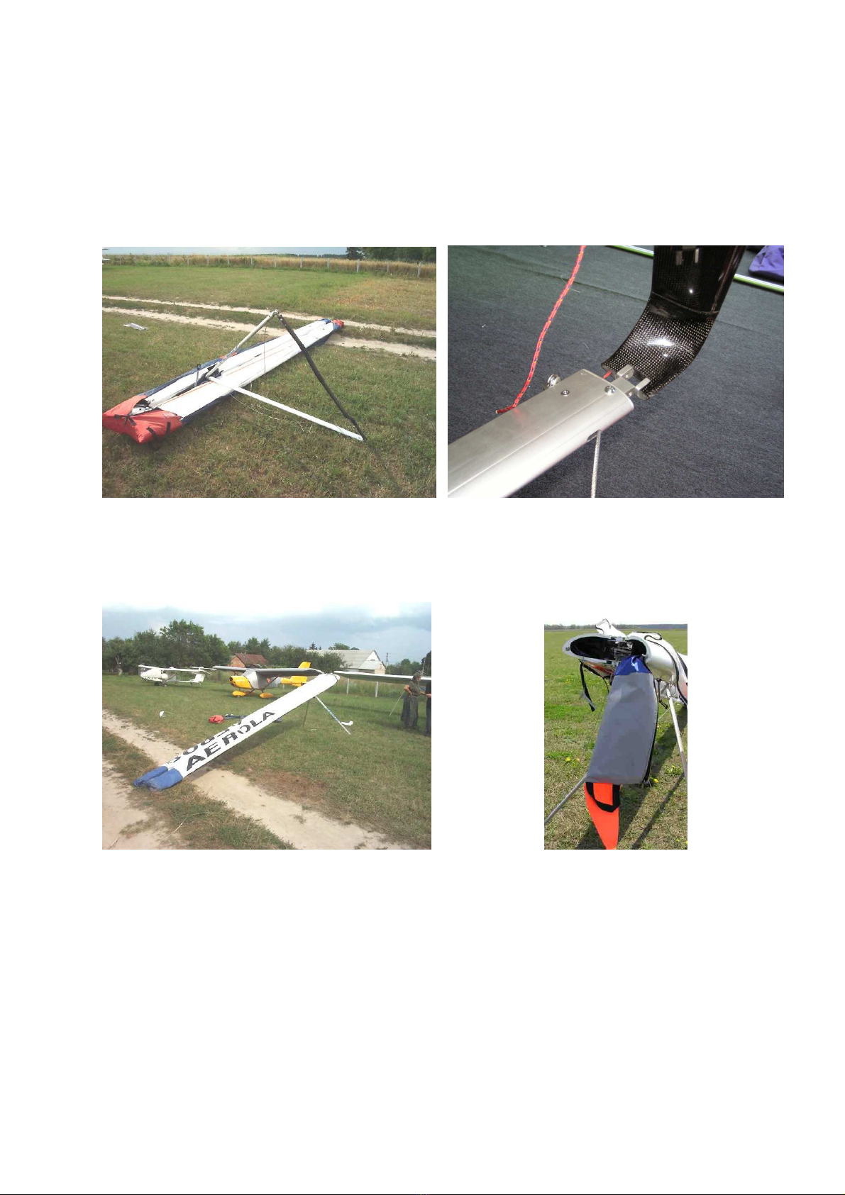
2.6. Fasten root zippers on the upper and lower sail by 1/3 of their way
2.7. Install winglets
•crew out the head from winglet stud
•Put the winglet on the tip so the stud will go through the hole in the tip
•crew the head on the stud and tighten it (winglet must not move on the
tip)
•
2.8.Connect the sail to the tip
•fold the tip a little, slip the front and back corner of the sail on the head
pins

9
•press the sail to the tip with clamp wall (be sure there are no wrinkles on
the sail between clamp wall and tip)
2.9. Put out the tip tube, fold down the tip strut as much as possible and put
the tip strut’s free end on the pin on the trailing edge. The tip strut side
edge must be under the angle on the tip rib’s bracket.
2.10.Lock the tip strut, connect top and bottom sail each other
2.11.Repeat steps 2.6 through 2.8 for another side
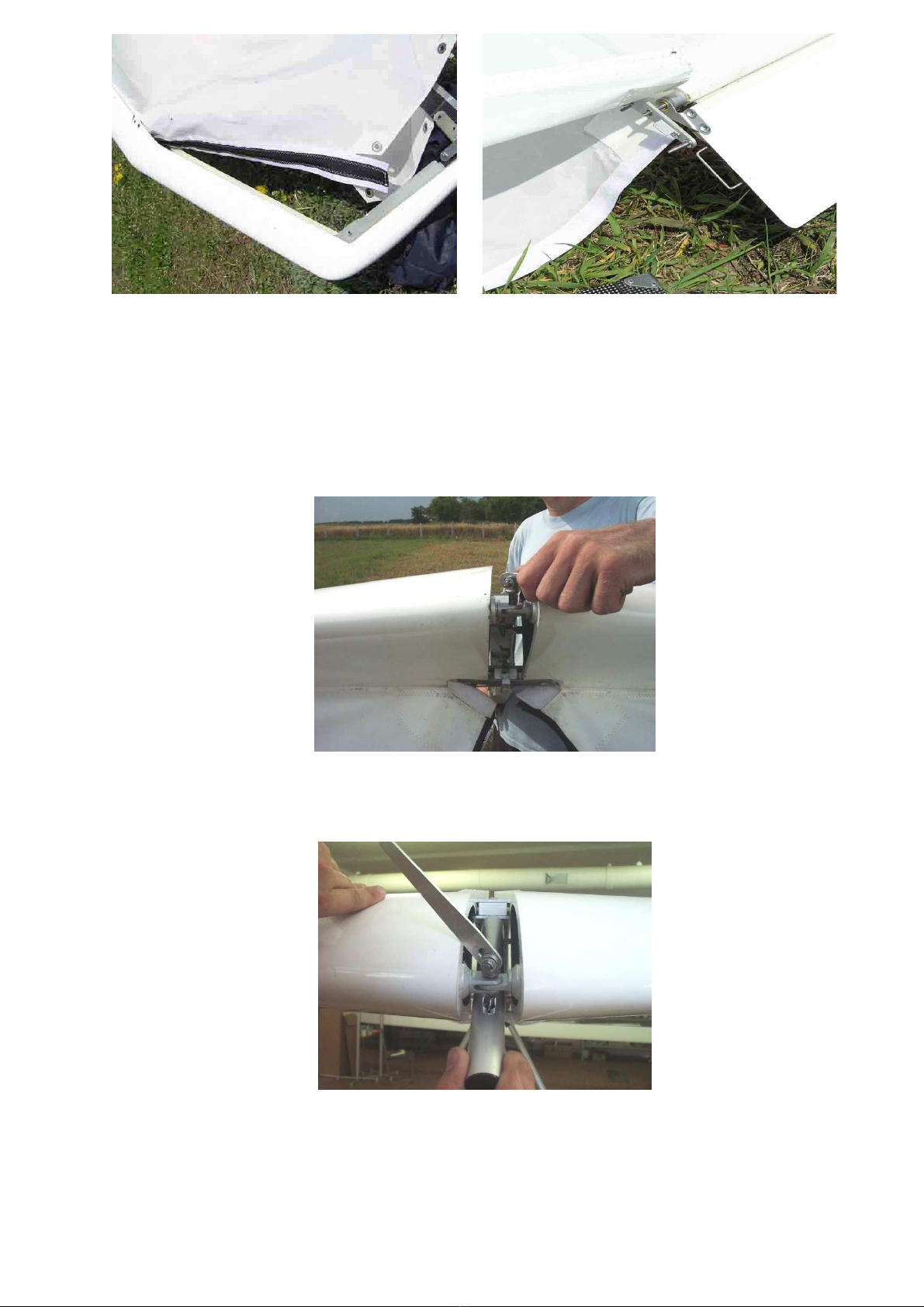
2.12. For one side at a time:
•et ribs to the trailing edge (don’t lock on center yet). Hook rubber of
the ribs wire to the ribs wire holding bracket. Make sure that each rib
end is properly installed into the trailing edge tube. The tube must be
placed between the limiting plates on the rib fork (end)

10
•Pull aileron rod out of the sail as far as possible
•Attach the arm for rib tensioning to the ribs cable and lock it. Tightening
force should appear when the arm is parallel to the keel beam. If the
tightening force appears from the very beginning, it means that either
the rib tips were not placed on the trailing edge tube or the rib
tensioning wire is jammed. It is necessary to check and correct all
irregularities, and after that tense the ribs
2.13. Repeat steps 2.12 for another side
2.14. Connect left and right safety wire each other
2.15. Connect flap controls to the flaps.
2.11. Attach aileron arms to the ailerons.
11
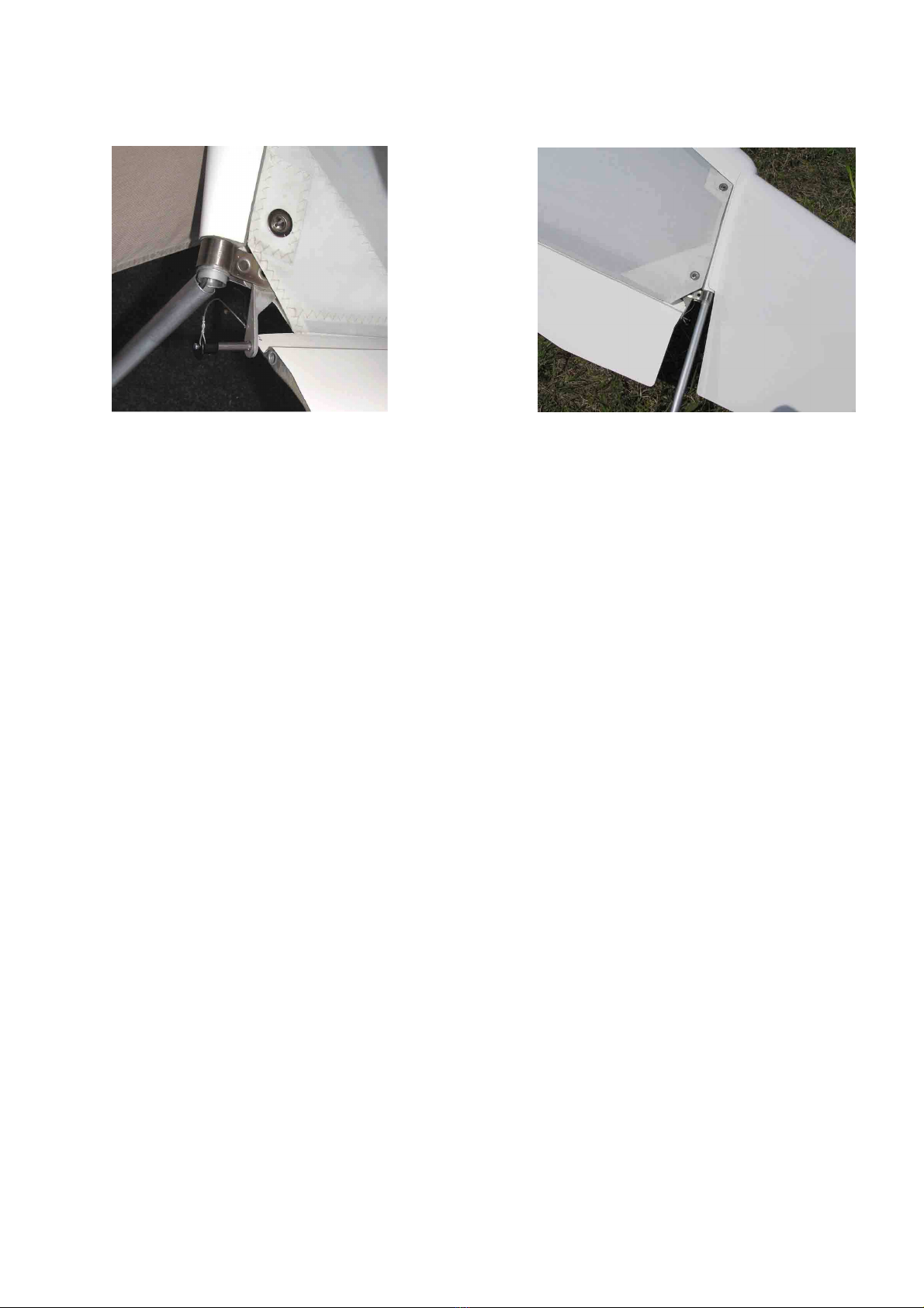
2.12. PADD installation:
•Put it on the pin on the tip rib
•Put out the tip tube and insert Quick Pin on other end
•Put in the tip tube.
The pin on PADD’s aileron side must be above the aileron’s pick-up
bracket
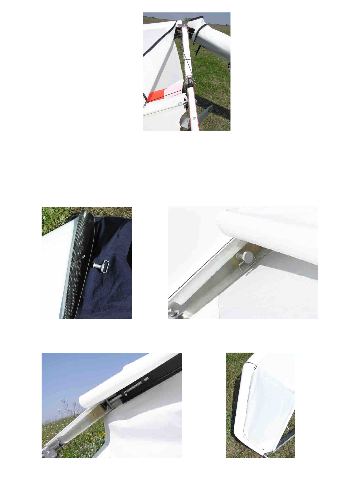
2.12. ide wires connection:
•Insert side wire end plate into the slot at the middle of upright and fix it
with Quick Pin
•There must be small slack on side wires with RWG off, if they are tighten
too much you must check if side wire freely go through the pulleys or
blocked some were
2.13.Install nose and back cover

12
ection 3. PREFLIGHT IN PECTION
3.1. Do complete preflight inspection of the glider. Check all parts and all
assemblies of the glider. Beginning at the nose go around the glider,
check all details of the construction. Finish inspection by checking the
keel tube and control frame.
The less you hurry the more you’ll inspect!
3.2. Check nose junction.
•The wires must be hooked in and secured.
•All bolts must be screwed and secured.
•The keel’s pulley lever must have no bends, the control wire must go
through the pulleys, the wire safety brace must have no bents and
control wire must do not have possibility to go out from the pulley
3.3. Check the tip area.
•The sail corners must be properly attached at the tip.
•The Velcro around tip strut must be fixed properly. There must be no
wrinkles on the sail which do not allow the PADD’s front edge to fit snug
to the sail.
•The PADD must turn easily, it should be impossible to remove the quick
pin without pushing the button.
3.4. Check ailerons
•Ailerons must turn easily, without extra efforts (to check this, unhook
side wires, turn ailerons holding them by the lever, to avoid damaging
them).
3.5. Check aileron rod
•The end of the aileron rod must be secured.
•The quick pin which connects the aileron arm to the aileron should not be
removable unless the button is pushed.
3.6 Check the rib N5 junction. Open the zipper at bottom surface.
•The aileron rod must be fixed at the control quadrant (sector) and
secured (locked)
•Control wires must go through the sector.
•Control wires must go through the turn pulley in the front part of the rib
N5
3.7. Check rib’s tips position
Walk along the trailing edge and check rib tips position.
•The trailing edge tube must be supported at tip rib pulleys
3.8. Check the flaps deflection.
•They must turn easily, without extra efforts.
• After unfixing flap control rope flaps must go up easily and quickly.
3.9. Check the root area.
•The trailing edge tube pins must be secured
•The bolt fixing the downtubes to the keel tube must be screwed
Open the bottom and top root zipper by two thirds of its travel.
•The ribs tensioning wire must be locked and secured properly.
•All control cables must go through the control pulleys
•Control cables must not be jammed.
•The RWG rod on the keel must be fixed and locked
•The RWG rope on the speedbar must easy turn the RVG pulley and after
releasing the rope the RVG pulley must turn back
•The stopper rope and rubber on the stopper rope must not be broken.
•Hang-in belt must be secured by the bolt, the nut should be locked, the
belt should have no damages
3.10. Check ailerons neutral set up angle

13
•
In neutral position the trailing edge of the ailerons must be on the same
level as flap’s trailing edge or ~5mm higher
3.11. Check side wires attachment.
•The side wires must be connected to the downtubes and should be
impossible to remove the quick pin without pushing the button
•The side wire must have slack if the RVG off and must have no slack if
the RVG on
3.12. Check control system.
Take the glider as before take off, move control frame right and left.
•The control frame must move easily, ailerons and PADD must move
properly.
14
ecti
on 4. PERFORMANCE AND FLIGHT CHARACTERI TIC
Check and adjust your harness. We strongly recommend that you hang as
low as possible (as close to the speedbar as possible). Be sure that no part
of the harness touches the speedbar while pilot moves over the whole
range as he or she will move in flight.
4.1. Take off
Make sure you are hooked in and check your position hanging in the
control bar.
Make the flaps ON by 1/3-1/2 way.
Make sure RWG is OFF. It is not allowed to take off with RWG ON
If the wind is more than 8m/s (18 mph) or is gusty, you have to have at
least one wire assistant on the nose wires and side assistant. The Phantom
has a slight tail heavy static balance, which does not take effect during
take off.
When you hold the glider prior to your take off run, you should keep the
nose slightly up and wings level.
The glider takes off easily in zero winds as well as with strong winds and
does not require any special methods of handling.
4.2. Flying
At first handling performances of the Phantom seem to be different from
those inherent in other gliders. The reason is that Phantom handles easily
at any speed. Don't worry, you'll soon get used to it. Make your first flight
in easy flying conditions.
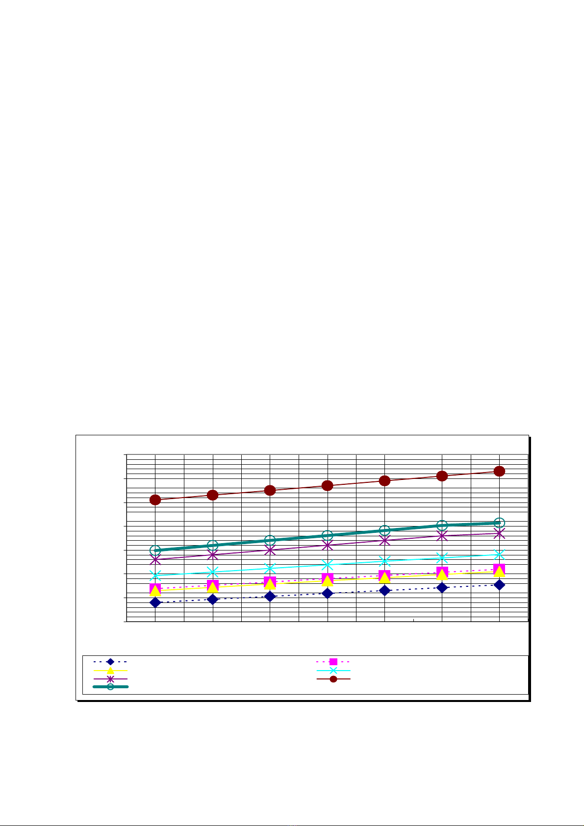
4.3. Flight peed
Remember that the range of flight speed depends on the wing load. If you
have big wing load and you fly at minimum speed for the small wing load,
you can get a stall.
Refer to the diagram below to determine trim speed that corresponds to
your hook in weight, and adjust hook in point in order to achieve this trim
speed. Trim speed must be a little higher than minimum sink speed. o, in
thermals when you want to fly at min. sink speed, you should push the
bara little.
Flight speed
25,0
30,0
35,0
40,0
45,0
50,0
55,0
60,0
70 75 80 85 90 95 100
Hook in weight, kg
Speed, km/h
Stall speed, full flaps Safety Vmin, full flaps, stright flight
Stall speed, flap 0 Safety Vmin, flap 0, stright flight
Min sink speed Max glide ratio speed
Trim speed

15
Don’t fly in turns at speed less then min. afe bank speed. ee diagram
below.
At speed over 90-100km/ in gusty and bump conditions you can get a
non-periodical hits on the wing, which appears due to turbulence.
4.4. Handling in turn
Phantom responds quickly to any bar movement, control efforts are small.
The glider turns easily and quickly at speed a little higher than the trim
speed. As the glider begins to turn, you may push the bar out a little for
making the turn faster, and then move it back. Don’t do this at low
speed. You must keep the speed corresponding to the bank angle.
Phantom is stable in multiple 360-degree turns in both directions and has
no sideslip.
4.5. Using RVG
RVG system is designed for increasing glide ratio at high speed. That
system decrease the aileron set up angle on 3deg. Therefore the pitch
stability is decreased also and, as result, bar pressure becomes lower. Trim
speed with RVG ON becomes higher on 12-14km/h.
•Climbing. RVG mode – OFF(rope is released). Excellent control at low
speed, best possibility for finding good climb. Too much bar pressure at
high speed.
•Gliding. RVG mode –ON (rope is pulled). Use that mode if you are going
to fly for a long time at speed higher than 75-80km/h. Glider has best glide
ratio at high speed. Bar pressure do not make you tired during long flight
at high speed. That is quite difficult to climb with RVG ON due to high trim
speed and not that comfortable handling as with RVG OFF. Also in
Flight speed in bank
30,0
35,0
40,0
45,0
50,0
70 75 80 85 90 95 100
Hook in weight, kg
Speed, km/h
Safety Vmin, full flaps, 30deg bank Safety Vmin, full flaps, 45deg bank
Safety Vmin, flap 0, 30deg bank Safety Vmin, flap 0, 45deg bank

16
combination with backward CG position at low speed the pitch stability can
be not enough for climbing in turbulent conditions. o do not use that
mode for climbing.
4.5. Using flaps
The Phantom has flaps deflection range 0~55deg. After full flaps deflection
trim speed is decreased by 8~10 km/h and speedbar moves backward by
150 mm.
The 0 deg. flaps is the best glide ratio and min sink ratio configuration.
The 15-20 deg. flaps is the climbing configuration – glider has best control
with good sink ratio
Big flaps deflection angles are not recommended for climbing due to
substantial increase in sink speed and decrease in glide ratio. These big
angles can be used for landing and quick descent.
4.6. Landing
As the Phantom is a high performance glider, you should land only up the
wind and avoid going downhill. Phantom requires thorough handling during
landing.
For landing it is recommended to use from half flap up to full flap
configuration.
Make sure RWG is OFF. That is not allowed to land with RWG ON.
That is not allowed to do big flare up. In case of big flare there is high
possibility to hit the ground with the tip and damage the tip.
Keep the wings level, speed the glider up slightly and fly right down till the
altitude is 0,5 - 0,8 m from the ground to the speedbar. At this altitude
decrease descent rate by pushing slightly on the control bar. When you feel
the glider unresponsive to the bar movement, quickly ease the bar out all
the way before your feet touch the ground. With a good sharp final thrust,
the sudden increase in drag will slow the glider very suddenly and you will
land softly. In zero wind conditions you will make few steps to stop the
glider.
REMEMBER. Do not ease the bar out with surplus speed! It leads to sudden
flare up and falling. It is much better not to move the bar out at all, than
move it too early.

17
ection 5. BREAKDOWN Procedure
5.1. Remove nose cone
5.2. Unhook side wires
5.3. For one side at time:
•Put out tip tube
•Remove PADD
•Disconnect winglet
•Unlock tip strut
•Open clamp wall
•Put out top back corner of the sail from head pin
•Fold tip strut as much as possible (tip tube should be removed) and put
out it from the pin on the tip rib end
•Fold the tip a little and put out the sail from head pins completely
•Open zipper on the sail, put out the clamp wall from the sail
•Detach ailerons lever from ailerons
•Put aileron rod into the sail and fix it with a rubber ring
5.4. Repeat steps 3.3 for another side
5.5. Detach flap control from the flap
5.6. Ease ribs off
5.7. Detach the trailing edge tube from the keel beam
5.8. Fold ribs down, pulling by the cord at the tip of the ribs wire
5.9. Disconnect keel stinger
5.10. Disconnect nose tube and nose pin.
5.11. Detach the tip rib from the trailing edge tube
5.12. Wrap sail around the D-spar, trying to avoid wrinkles
5.13. Disconnect tips and put covers on the D-cell ends.
5.14. Fasten flaps and ailerons on the D-cell by Velcro.
18
5.15. Ensure that the zippers in the center are folded correctly and the
sliders do not go between the keel beam and the D-cells.
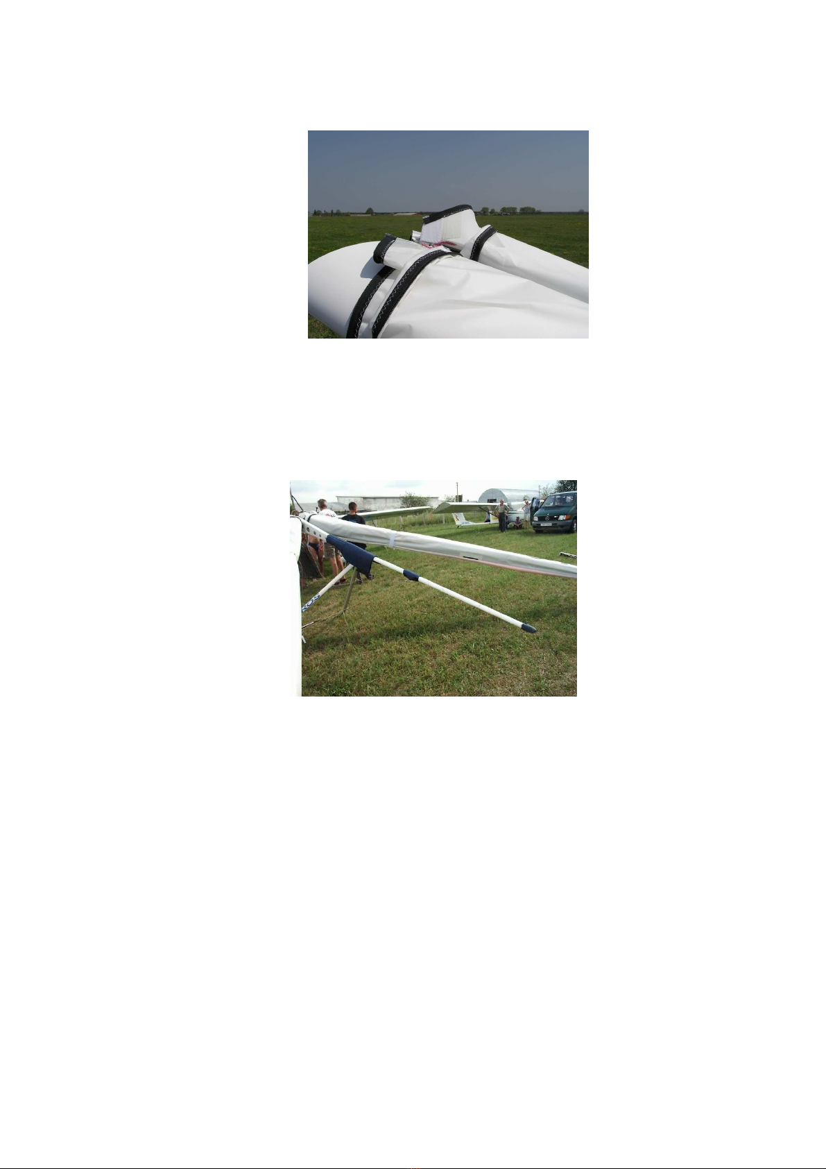
5.16. Put protective covers on the keel beam as follows:
-One big cover – at the place of attachment of the trailing edge tube and
ribs wire, wide part backwards;
-maller cover – at the place of attachment of rear wires;
-The smallest cover – at the end of tail tube.
-
5.17. Fold wings in.
5.18. Hide wingtips into the D-cells.
5.19. Put the glider cover on.
5.20. Put the glider down, upper side down.
5.21. pread the D-spars a little.
5.21. Disconnect the speedbar, turn each downtube on 180deg, fold them
leading edge down, put down tubes along keel slightly turn them to be
sure that leading edge does not touch the keel tube.

19
5.22. Pull the flap rope out so the flap’s pulley is out and put protective
cover on the downtubes end.
5.23. Always put the packed glider on earth or on the car with the zipper
upwards.

20
ection 6. Maintenance
6.1. Tuning
A correctly tuned glider is comfortable and has good handling in all allowed
flight modes. Phantom has a number of adjustment points that can be
used for changing its performance.
6.1.1. Hang point.
Trim speed should be different for different hook in weight. The more the
weight, the higher speed you’ll have (see Flight peed). Adjust hang point,
in order to achieve trim speed corresponding to your weight. If the glider
has already been tuned for lower weight, move the hang point backwards
for a heavier pilot.
6.2. Regular inspections of the glider
It is necessary to check your glider regularly for damages, possible
structural deformations, operational depreciation, tuning. You have to
inspect frame (D-spars, ribs, keel, trapeze), wires, all hinges and fittings,
bolt connections, sail, control system tuning.
6.2.1. Instruments and facilities
- Four supporting struts for proper setting up the glider relatively to the
ground level
- Electronic inclinometer for measurement aileron setting up angle and
angle of the control surfaces deflection
- Lamp or lighter for searching cracks in D-spars
- Ruler and slide caliper
- et of spanner and other bench tools
6.2.2. Inspection intervals
•Before the first use;
•After each rough landing, in order to find any possible structural
deformations;
•After every 100 hours of flight or annually, whatever comes earlier.
6.2.3. Frame inspection
•Inspect D-cells with the view to find any distortions, damage, cracks,
especially at root fitting area, spar belt area. If you found some cracks on
the outer surface of the D-spar skin, use the lamp for checking if this crack
exists on the outer skin – light the crack zone and look inside the D-spar, if
you see the light inside the D-spar, that mean you have a crack on the
outer skin. If any D-cell damage detected, seek advice and assistance in its
repair from your local dealer. Don’t make repair yourself, unless you have
experience with repair of carbon plastic structures.
•Inspect control frame wires and all control system wires, looking for
broken threads, tear and signs of corrosion and replace them if you found
any.
•Check all bolting. Bolts should be tightened and locked. Where self-
locking nuts are used, not less than 2 thread coils should be visible.
•Check the keel beam and ribs, looking for permanent deformation,
dimples, signs of corrosion, cracks, especially near bolts and rivets.
•Check rib hinges. Axial play must not allow the rib end to move more
then 3mm. If the rib end moves more, you have to bush the hinge hole for
preventing such axial play.
6.2.4. Check the wing anhedral angle. Put the glider on the supporting
struts – One strut on the nose, another on the keel near rear wire fixing
point, other two on the left and right side of the wing at the middle of the
D-spar span. Align the keel tube with the horizon level. Measure the
Other Aerola Aircraft manuals

Popular Aircraft manuals by other brands


Van's Aircraft
Van's Aircraft RV-8 Construction manual

SFC
SFC Cessna 182Q Quick reference handbook

X-Crafts
X-Crafts Embraer EJets Series user manual

airwave
airwave Gecko owner's manual

Atec
Atec 321 FAETA NG Flight and operation manual

Aerospace Logic
Aerospace Logic FL-100-R Operation and installation guide


