Aeromax KHP0041 Manual
Air Source Heat Pump
Installation Manual
Model numers:
KHP0038: 6kw Heat Pump
KHP0039: 8kw Heat Pump
KHP0040: 12kw Heat Pump
Model numbers:
KHP0041: 4kW Heat Pump
KHP0038: 6kW Heat Pump
KHP0039: 8kW Heat Pump
KHP0040: 12kW Heat Pump
KHP0042: 15kW Heat Pump
A9317D
Air Source heat Pump
Installation and Maintenance Manual

2
2

3
SITING THE UNIT
WATER CONNECTIONS
ELECTRICAL CONNECTIONS
CONTROL WIRING (OPTIONAL)
POWER WIRING
FLUSHING WATER AND AIR
CHECKING FOR WATER LEAKS
CONFIGURING & CHECKING THE SYSTEM
Code Description
KHP0041 AEROMAX PLUS 4KW
KHP0038 AEROMAX PLUS 6KW
KHP0039 AEROMAX PLUS 8KW
KHP0040 AEROMAX PLUS 12KW
KHP0042 AEROMAX PLUS 15KW
INSTALLATION
Air / Water Cycle Heat Pump
Contents Page
R-410A - General info 4
Safety procedures 6
Dimensions and clearances 8
Installation & Technical data 10
Water connections 12
Electrical connections 20
Connection ofAuxiliary Accessories 22
System test 24
Unit protection devices 26
Additional System Diagrams 29
Installation Pack 36
Optional Installation Accessories 41
7day hot water programmer 43
Programmable room stat 55
Spare Part List 71
Rating Tables 75
Maintenance. 80
3

4
Introduction
The information in this manual is to provide general
assistance in the selection ofequipment. The
responsibility for the specification ofthe equipment must
however remain that ofthe installer and any consultants
or designers concerned with the installation, specification
or design.
Any water distribution and central heating installation
must comply with the relevant recommendation ofthe
current version ofthe Regulations and British Standards
listed below:
Building Regulations
I.E.E. Requirements for Electrical Installations (BS7671)
Water Regulations Manual Handling Operations
Regulations
British Standards BS6798, BS5449, BS5546,
BS5440:1, BS5440:2, CP331:3, BS6700, BS7593 and
BS7671. Health and Safety Document No 635.
When installing unvented hot water systems section G3 of
the Building Regulations should be adhered to. An
annual inspection would also be required to ensure safe,
long term operation.
Please note: Kingspan Renewables do not accept any
responsibility for matters ofspecification, design or
selection or for the effectiveness ofan installation
containing one ofour products unless we have been
specifically requested to do so.
Important Note - Included in the Aeromax Plus
introduction pack is the Kingspan Renewables 2-year
extended warranty registration card. Please use this card
to register within 30 days of commissioning/occupation if
new build, and ensure the homeowner benefits from the
extended warranty. This needs to be completed by both
the Approved Installer and the current homeowner (or a
signature ofdeveloper is required ifnew build). The
registration card is free post and is logged by our warranty
department.
In the unlikely event of failure ofthe Aeromax Plus heat
pump, return ofthe card ensures that the homeowner’s
warranty claim is dealt with efficiently.
All goods are sold subject to our Conditions ofSale (see
Web site for details).
• This heat pump adopts the new HFC refrigerant
(R410A) which does not destroy ozone layer.
• R-410A refrigerant operates at 50%-70% higher
pressures than R-22. Be sure that servicing equipment
and replacement components are designed to operate
with R-410A.
• R-410A refrigerant cylinders have a dip tube which
allows liquid to flow out with the cylinder in a vertical
position with the valve at the top.
• R-410A systems should be charged with liquid
refrigerant. Use a commercial type metering device in
the manifold hose in order to vaporize the liquid
refrigerant before it enters in the unit.
• As for other HFC, R-410A refrigerant is only
compatible with oils recommended by the compressor
manufacturer.
R-410A - General info
• A vacuum pump is not enough to remove moisture
from oil.
• Oils absorb moisture rapidly. Do not expose oil to
atmosphere.
• Never open system to atmosphere while it is under
vacuum.
• When the system must be opened for service, break
vacuum with dry nitrogen and replace filter driers.
• Do not vent R-410A into the atmosphere.
Use this unit only for factory approved applications.
The capacity and unit code are stated on the nameplate
data.
CAUTION:
• Do not leave the heat pump casing open to atmosphere any
longer than the minimum required for installation.
• Oil in the compressor is extremely susceptible to moisture
absorption.
• The maximum residual quantity of oil used for tubing is 40
mg/10m.
5
Unit protection devices
Check List
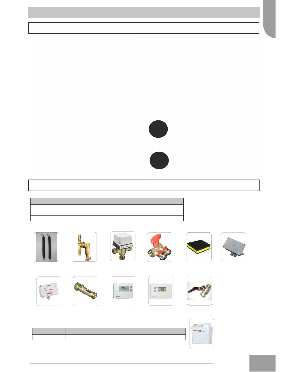
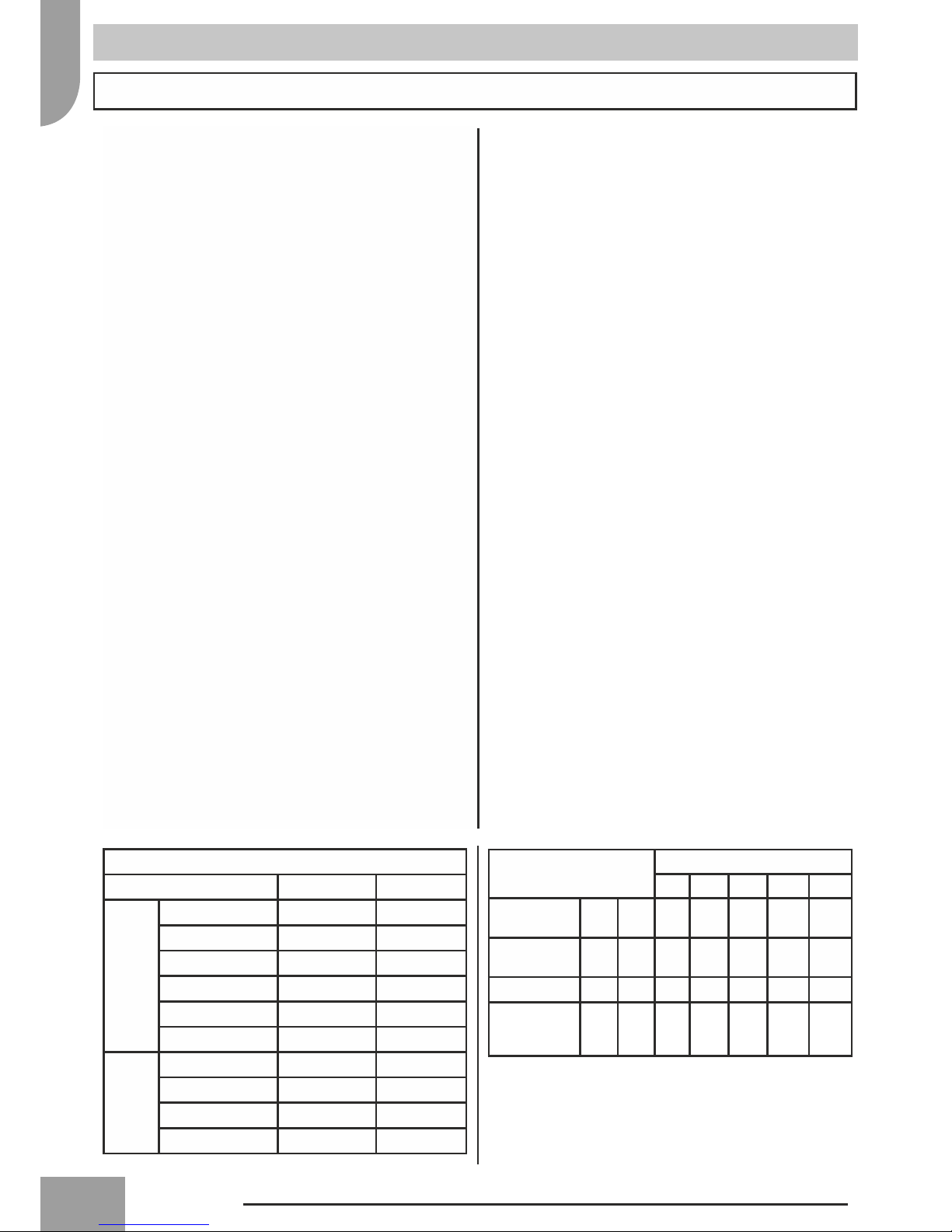
The following items are required for the installation ofthe Aeromax Plus Air Source Heat Pump
Product Code Description
KHP0029 4kW, 6kW & 8kW Installation Pack
KHP0030 12kW Installation Pack
KHP0026 15kW Installation Pack
Pack Contents
2 x 750mm flexible
hoses including 90°
elbow, pre-insulated.
W Plan diverter valve
(heat pump specific) Anti vibration padsFlush & fill ports
(except 15kW)
Diagnostic indicator 2x Full bore isolating
valve with lever arm
System Antifreeze / Inhibitor - Clear
Product Code Description
KHP0023 1 x 25 litre system antifreeze inhibitor - Clear
Introduction
The following check list has been prepared to assist you in
understanding the differences from other types ofheating
systems you may have installed and help to understand
and comply with all ofthe technical details contained
within this document to ensure a successful installation.
System cleaning and Water Characteristics
• In the case ofa new installation, or cleaning the circuit,
it is necessary to perform a preventive cleaning ofthe
system. In order to guarantee the good operation of the
product, each time you clean the system, replace the
water or add glycol, check that the liquid appears clear,
without visible impurities and that the hardness is less
than 20°f
• To help protect the heat pump from any heating system
contamination; the system filter should be fitted
internally on the return pipe.
Recommended system cleansers and inhibitors are listed
below.
Fernox F3 System Cleanser
Fernox HP-15c combined antifreeze and inhibitor
Sentinel
All external connecting pipe work should be suitably
insulated using Armaflex or similar.
Radiator System Circuit
• As the Aeromax Plus generates lower temperatures
than a conventional boiler the radiators should have
been designed to suit the lower mean temperature.
• The basic controls within the standard installers pack
and the parameters on the heat pump are optimised
for use on radiator systems.
Retrofit Situations
• The heat exchanger should be protected from
particulate contaminates in the water circuit. The
existing radiator circuit must be chemically cleaned
and thoroughly flushed before installation when fitting
in a retrofit situation.
Installation Pack
1 x 25 litre clear - system
antifreeze inhibitor
25L Heat Pump
Anti Freeze
Concentrate
For systems using under floor heating, boiler
back up or clients wishing to alter the
operating parameters of the unit; we
recommend the purchase ofour advanced
controller. See manual for product code
KHP0008.
It is the installer’s responsibility to ensure
correct sizing and provision ofboth the
domestic circulating pump & any associated
central heating expansion vessel
NOTE
NOTE
1 x System filter
Programmable room stat 7 day hot water
programmer
Flow setter
Immersion Heater
Controller

6
Safety procedures
Important safety information is displayed on the product and in this Manual. Please read this
installation manual carefully before installing the unit. It contains further important
instructions for proper installation.
Explanation of illustrated marks
Indicates prohibited items. Indicates mandatory items. Indicates cautions (including danger/warnings).
Explanation of indications
DANGER
WARNING CAUTION
Indicates contents will cause death
or serious injury ifused incorrectly. Indicates contents could cause
death or serious injury ifused
incorrectly.
Indicates contents could cause an
injury or damage to property,
furniture or pets ifthe instructions
are not followed carefully.
General notes
• Please ensure this manual is read thoroughly and kept
for future reference.
• Before any repairs or maintenance are carried out an
assessment ofthe potential risks must be undertaken,
and appropriate measures taken to ensure the safety of
all personnel.
• Do not attempt to repair, move, modify or re-install the
unit on your own.
• Ideally a fully qualified competent MCS installer (such
as those registered under the micro certification scheme)
with prior knowledge ofair to water heat pumps should
be used to install and/or commission the unit.
• All of the manufacturing and packaging materials used
for your new appliance are environmentally friendlyand
can be recycled.
LIABILITY The manufacturer declines any liability
and invalidate the unit warranty for damage resulting
from:
• Improper installation; including failure to follow
instructions in the manuals.
• Modifications or errors in the electrical or
refrigerant or water connections.
• Unapproved units coupling; including other
manufacturers units.
• Use of the unit under condition other than those
indicated.
Units handling
!!
Ensure adequate personal protective equipment is used.
Inspect equipment for damage due to improper transportation or handling: file an immediate claim with
the shipping company.
Dispose ofthe packaging material in accordance with local requirements.
When lifting the unit, absolutely do not use hooks inserted in the side handles, use special equipment
(e.g. lifting devices, trolleys etc.).
Do not step or put anything on the indoor/outdoor unit. It may cause an injury or damage the unit.
Do not place containers filled with liquids or other objects onto the unit.
!
!
!
!
This appliance must not be used by persons (and children) with reduced physical, emotional or
mental faculties or by persons with no experience or knowledge if they are not under the control of
a person responsible for their safety, or if not instructed to the use of this appliance. Make sure
that children do not play with the appliance.
7
Safety procedures
Unit installation
Electrical connections
The installation must be carried out by a qualified
installer.
DO NOT INSTALL IN A PLACE...
• Difficult to access for installation and maintenance.
• Too close to heat sources.
• That might increase the vibration of the unit.
• Which cannot bear the weight of the unit.
• Subject to a risk of exposure to a combustible gas.
• Exposed to oils and vapours.
• With particular environmental conditions ie windy
location.
CHOOSE A PLACE...
• Where noise and discharged air do not disturb neighbours.
• Protected from strong winds.
• That allows for the clearances required.
• Which will not obstruct passageways or doors.
• With floor structure adequately strong to support unit
weight and minimize vibration transmission.
Note...
Fix the unit with locally purchased bolts buried in the block.
If the unit is installed in areas where heavy snowfalls may
occur, it is necessary to raise its level at least 200mm above
the usual snow level or alternatively to use the outdoor unit
wall mounting bracket kit. See Kingspan optional extras
such as the “snow feet”(Anti vibration foot KHP0044 )
recommended for exposed areas to help create an air gap
under the unit.
CAUTION
!
!
All field electrical connections are the responsibility of
the installer.
DANGER
Electrical shock can cause severe personal injury
or death. These operations are to be carried out by
qualified personnel only.
!WARNING
• This unit complies with Machinery Directive
(2006/42/EC), electromagnetic compatibility
(2004/108/EC) and pressure equipment (EEC/97/23)
Directives.
• To avoid electric shock or fire make sure these
operations are carried out by qualified personnel only.
• Ensure that national safety code requirements have been
followed for the main supply circuit.
• Follow all current national safety code requirements.
• Ensure that a properly sized and connected ground wire
is in place.
• Check that voltage and frequency of the mains power
supply are those required; the available power must be
adequate to operate any other possible appliances
connected to the same line.
• Check that the impedance of the mains power supply is
in conformance with the unit power input indicated in
the rating plate ofthe unit.
• Make sure that properly sized disconnecting and safety
switches are installed.
• The disconnection devices from the mains supply must
allow full disconnection under the conditions provided
for by overvoltage class III.
• Connect the connecting cable correctly. If the
connecting cable is connected in a wrong way, electric
parts may be damaged.
• Connection to the mains supply is of the Y type;
therefore, the cable must only be replaced by a
qualified technician in order to prevent any risk.
• Use the specified cables for wiring and connect them
firmly to the terminals.
• Be sure to provide grounding; inappropriate grounding
may cause electric shock.
• Do not connect ground wires to gas pipes, water pipes,
lightning rods or ground wires for telephone cables.
DANGER:
Do not modify this unit by removing any ofthe safety
guards or by by-passing any ofthe safety interlock
switches.
FINAL CHECK
• If refrigerant gas leaks out during the installation work,
ventilate the room immediately.
• If refrigerant gas leaks into the room and flows near a
fire source, such as a cooking range, poisonous gas is
generated.
Contact the manufacturer ifone ofthe following
events takes place:
• hot or damaged power supply cable;
• unusual noise during operation;
• frequent operation of the protection devices;
• unusual smell (such as smell of burning).
WARNING
!WARNING
!
8
Minimum installation clearances in mm are shown in fig. 2 (single installation) and fig. 3 (serial installation)
Note: The height ofthe obstacle at both front and rear side should be lower than the height ofthe outdoor unit.
A B C D E F G H L weight
KHP0041 908 821 326 350 87 356 466 40 60 56
KHP0038 908 821 326 350 87 356 466 40 60 58
KHP0039 908 821 326 350 87 356 466 40 60 68
KHP0040 908 1363 326 350 174 640 750 44 69 99
KHP0042 908 1363 326 350 174 640 750 44 69 124
Safety procedures
!
CAUTION
• Ensure adequate personal protective equipment is used.
• Extraordinary maintenance operations must be carried
out by specially trained personnel.
Disconnect the mains power supply prior to any
maintenance operations or prior to handling any
internal parts ofthe unit.
CAUTION
• This equipment contains refrigerant that must be
disposed ofin a proper manner.
• When disposing of the unit after its operational life,
remove it carefully.
• The unit must then be delivered to an appropriate
disposal centre or to the original equipment dealer
for proper environmentally compatible disposal.
!!
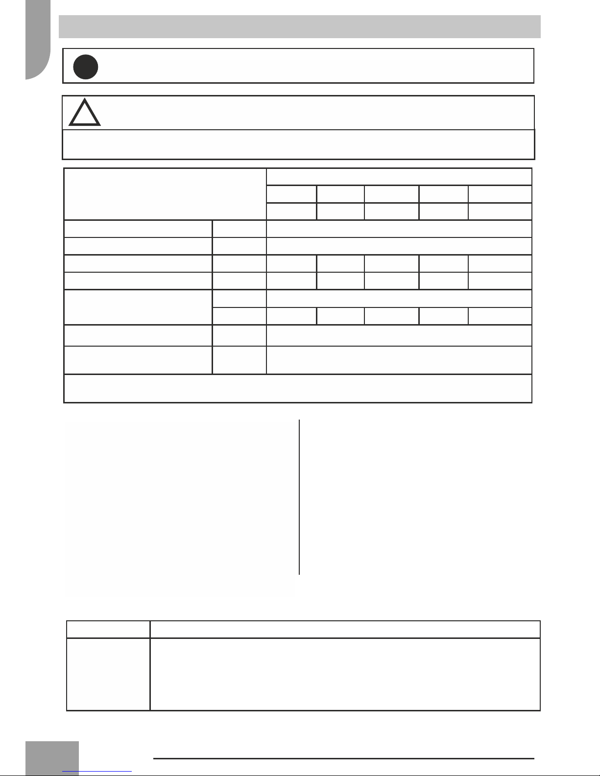
Dimensions and Clearances
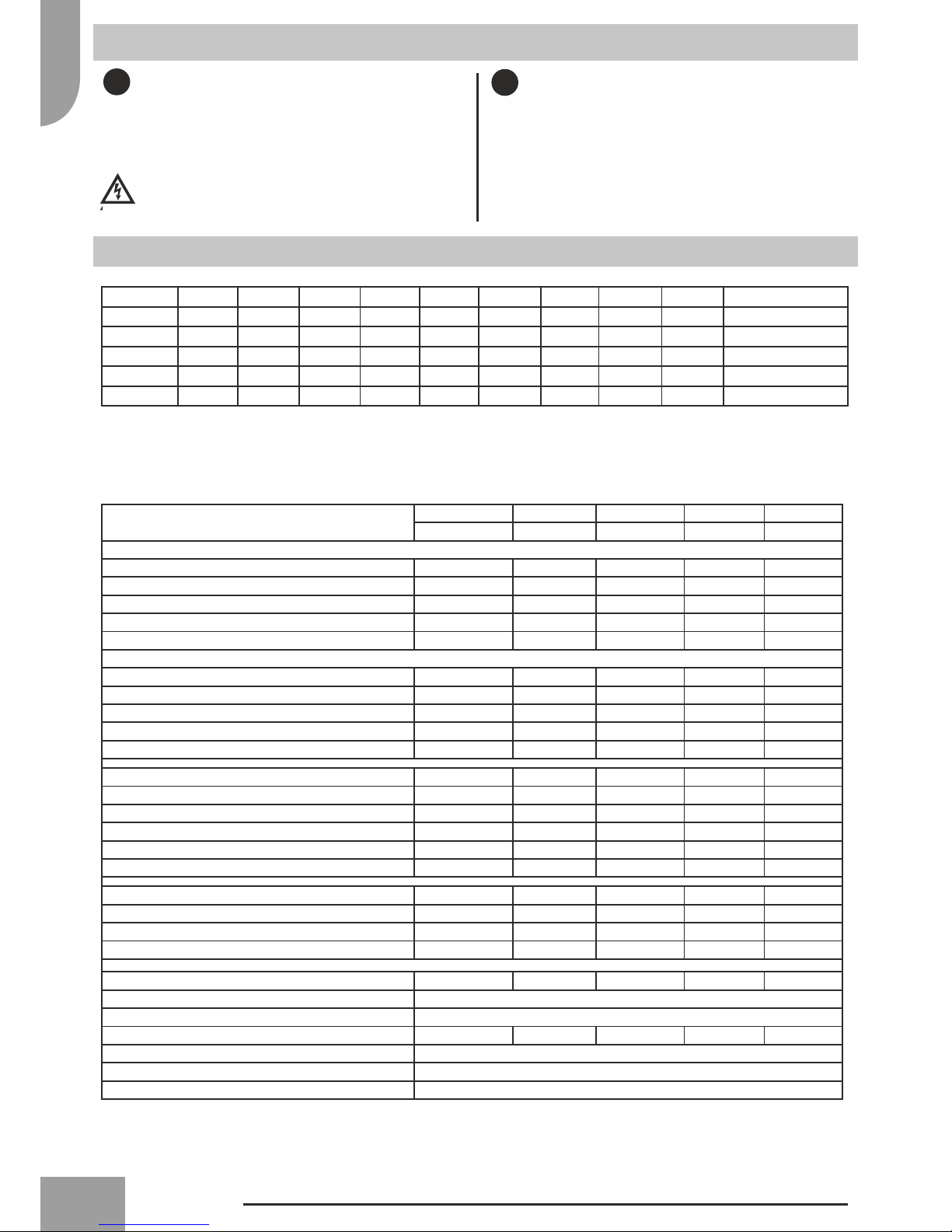
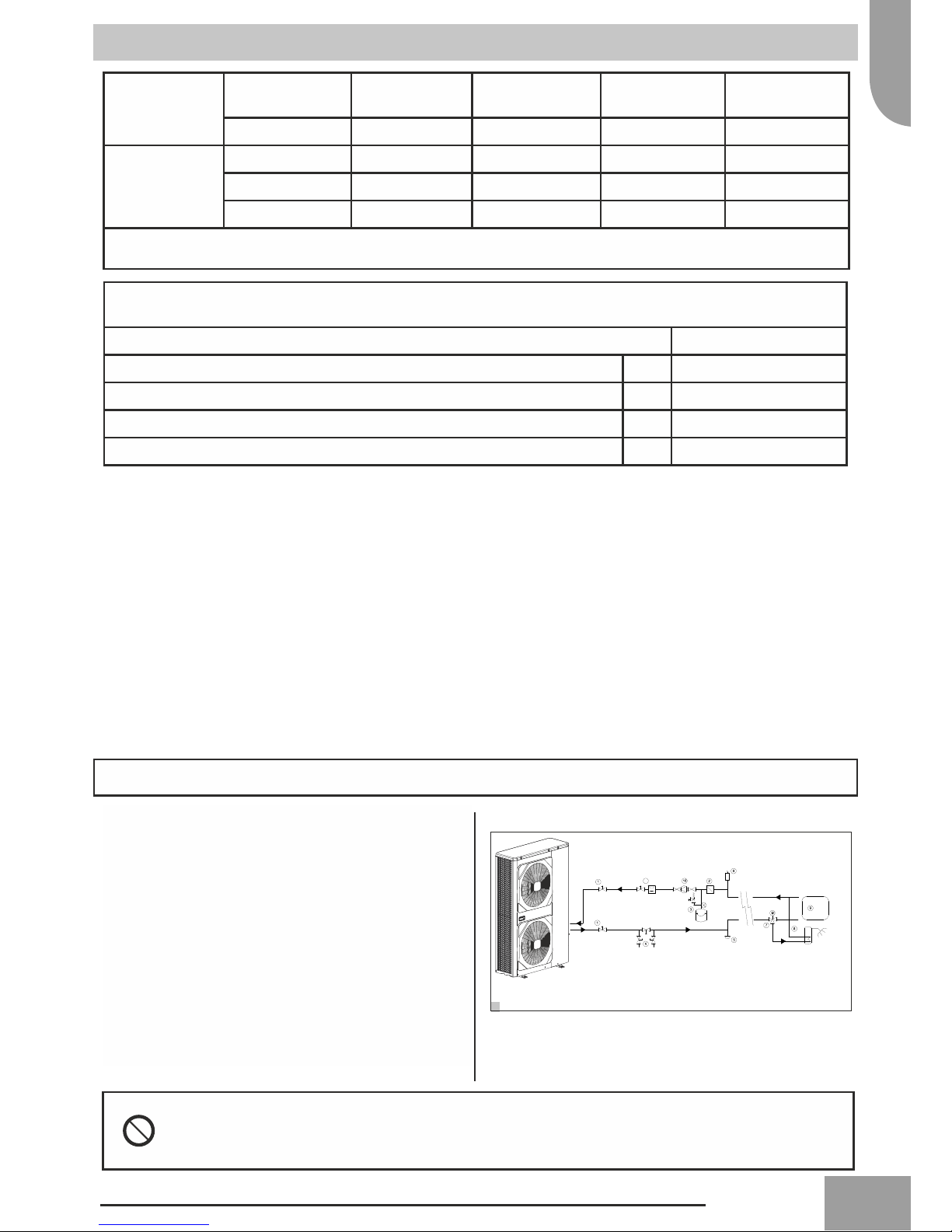
Specifications KHP0041 KHP0038 KHP0039 KHP0040 KHP0042
4kW 6kW 8kW 12kW 15kW
Data at Condition 1: A 7db/6wb W30/35 (EN14511)
Nominal heating capacity kW 4.1 5.8 7.2 11.9 14.5
Power input kW 1.01 1.37 1.82 3.01 3.57
Current Input (A) 4.35 5.95 7.91 13.1 15.5
COP (kW/kW) 4.05 4.24 3.95 3.94 4.06
Eurovent class, heating A A B B A
Data at Condition 2: A 7db/6wb W40/45 (EN14511)
Nominal heating capacity (kW) 3.9 5.8 7.4 12.9 14
Power input (kW) 1.22 1.90 2.32 4.26 4.36
Current Input (A) 5.3 8.26 10.1 18.5 18.9
COP (kW/kW) 3.2 3.06 3.18 3.03 3.21
Eurovent class, heating A B B B A
Water pressure drop, kPa (Condition 1) 16 9.5 14.5 26 33
Fan Power Input (kW) (Condition 1) 0.09 0.09 0.099 0.191 0.19
Fan Speed (RPM) (Condition 1) 680 680 680 710 - 730 780-820
Current Input (A) (Condition 1) 0.65 0.65 0.85 1.63 1.18
Sound power level, heating‡ dB(A) 62 62 64 67 68
Sound pressure level, heating‡ dB(A) 42 42 44 47 48
Nominal Flow Rate (l/min) 12 16.8 19.8 34.8 41.4
Nominal Flow Rate (l/min) (Radiators) 8.0 9.8 10.8 21.0 31.7
Minimum Flow Rate (l/min) (to operate flow switch) 5 8 8 8 8
Maximum Flow Rate (l/min) 15 20 25 40 50
Refrigerant Content (g) R410A 1195 1350 1810 2450 3385
Oil Type Ester Oil VG68
Compressor Type Rotary DC Inverter Technology
Net Water Volume (L) 0.8 0.8 1 2.3 2.3
Water Connections 1" ISO228 (BSP) Male
Maximum Water Pressure (kPa) 300
Product Category (EN14511) – Packaged Monobloc.
Above data applies to new, clean heat exchangers
Factory defult settings for heating are 55°C flow temp. To alter this you will be required to purchase the advanced
controller KHP0008

9
2
3
1
150
500
1000
100
150 300 300 300
200
1000
300
200
300
1000
1000 300 1500 2000 200
150
200
150 300
500
1000 150
Dimensions and Clearances

10
Installation
Drain hose and base pan knockouts (Fig. 6)
How to remove the front panel (Fig. 5)
Opening cable knockouts
There is a pre-cut part that can be removed for running
wires. Do not remove the unit front panel for easier drilling
of the knockouts. The pre-cut section ofthe sheet can be
removed by punching the 3 connection points along the
line first using a screwdriver and finally with your hands
(See Fig. 4).
When the cable knockout is open, remove the burrs and
fit the cable protective bush supplied with the unit for
cable
1.Remove screws ofthe front panel (See fig. 5). 2. Pull the front panel downward with the handle.
See fig. 6.
In case ofdraining through the drain hose, attach the
drain nipple (A) and use the drain hose (Inner diam:
16mm) sold on the market. When there is a possibility of
freezing ofthe drain in cold weather maintain a
continuous downward slope in the drain pipe to prevent
the drain becoming blocked by ice.
The drainage ability increases when knockout holes on
the base pan are opened. (Open the knockout hole to
outside using a hammer (B), etc.). Take care not to
damage the evaporator coil when opening the knockout
holes. We recommend that the knockout holes are opened
for all UK & Ireland installations.
Operating limits (Fig. 10)
Operation in heating: See fig. 10
A- Outdoor air temperature (°C)
B- Outlet water temperature (°C)
Before installation, check strength and levelness ofthe
base so that abnormal noise is not generated. According
to the dimensions and clearances, fix the base firmly
with the anchor bolts (Anchor bolt, nut: 4 off M10).
If the outdoor unit is installed in a very windy place,
protect the fan with a wind protection screen and check
that it works correctly.
Radiator Design / Defrost Cycle
The Aeromax Plus system typically requires at least one
radiator (usually located in the same location as the room
thermostat) to remain “open circuit” with no thermostatic
radiator valve fitted.
The minimum design criteria to be employed by the
installer is to allow 3 ltr per kW ofnominal out ofthe heat
pump.
For example:
8kW Aeromax Plus x 3ltr = 24 ltr ofwater to act as open
loop.
(Fig. 4)
Circulating Pump
A circulating pump is not supplied as part of the
Aeromax Plus installation pack. A suitable circulating
pump must be specified based on the pressure loss in the
system.
Pressure loss curves for the Aeromax Plus are shown in
fig. 11.
(Fig. 11)
Climatic Curve
To qualify as a Weather Compensated heat pump the
Aeromax Plus is pre-programmed with a climatic curve.
See fig. 12.
Care must be taken to ensure this curve is suitable for
the application and heat emitters used. There are 12
pre-programmed climatic curves selectable using the
User Comfort Interface KHP0008. A custom climatic
curve can also be programmed.
(Fig. 12)

11
6
5
4
1
2
3
1
2
3
600150 150
430
400
363
B
A
37
Foundation Specification
Foundation bolt M10 (3/8”)
Thickness ofconcrete 120mm
Length ofbolt 70mm
Weight-bearing capacity 320kg
7
12
Water connections
Make the plate heat exchanger hydraulic connections with
the necessary components, using material which will
guarantee that the screwed joints are leak proof. The
typical hydraulic circuit diagram shows a typical water
circuit installation in an air conditioning system.
For an application with a water circuit, the following
recommendations must be taken into account:
1. The pump must be fitted immediately before the heat
exchanger and after the connection to the system
return (unit without hydronic module).
2. It is advisable to install shut-off valves to allow
isolation ofthe most important circuit components, as
well as the heat exchanger itself.
These valves (ball, globe or butterfly valves) should
produce a minimum loss ofcharge when they are open.
3. Provide unit and system drains and vents at the lowest
and highest system points respectively.
4. Install purges in the higher sections ofthe installation.
5. Flow setter should be installed after the pump on the
return circuit. Leaving approx 200mm to avoid any
turbulence from the pump
6. All piping must be adequately insulated and
supported.
Installation ofthe following components is obligatory:
1. The presence ofparticles in the water can lead to
obstructions in the heat exchanger. It is therefore
necessary to protect the heat exchanger inlet with a
filter or dirt separator. The filter mesh gauge must be at
least 10 mesh/cm2.
2. After assembling the system, or repairing the circuit,
the whole system must be thoroughly cleaned with
special attention paid to the state ofthe filters.
3. Flow rate control is made by the control valve on the
flowmeter/setter installed after the pump (see fig 9
item 11).
4. When water has to reach temperatures below 5°C, or
the equipment is installed in areas subject to
temperatures below 0°C, it is necessary to mix water
with inhibited monopropolyne glycol in a suitable
concentration.
System cleaning and Water Characteristics
In the case ofa new installation, or cleaning the
circuit, it is necessary to perform a preventive
cleaning ofthe system. In order to guarantee the
good operation ofthe product,each time you clean
the system, replace the water or add glycol, check
that the liquid appears clear, without visible
impurities and that the hardness is less than 20 °f
Fig. 8 - Integrated water circuit
1.Automatic valve with air vent
2.Flow switch
3.Pressure relief valve (300kPa, outlet 1/2’)
4.Temperature probe
Fig. 11
A- Water flow rate, (l/s)
B- Pressure drop (kPa)
Water Connections (Fig. 8/9/11)
Pipe water content
Internal Diameter Outer diameter Liters / meter
copper 12 mm 14 mm 0,11 l/m
14mm 16 mm 0,15 l/m
16mm 18 mm 0,20 l/m
20mm 22 mm 0,31 l/m
25mm 28 mm 0,49 l/m
32mm 35 mm 0,80 l/m
steel 12.7 mm (1/2'')" " 3/8''Gas 0,13 l/m
16.3 mm (5/8'')" " 1/2''Gas 0,21 l/m
21.7 mm (7/8'')" " 3/4''Gas 0,37 l/m
27.4 mm (11/16'')" " 1”Gas 0,59 l/m
Unit Aeromax Plus
4kw 6kw 8kw 12kw 15kw
Nominal water
flow Std l/s 0.2 0.28 0.33 0.58 0.69
Working
pressure
Max kPa 300 300 300 300 300
Filling pressure Min kPa 120 120 120 120 120
Difference in
level with unit
at lowest level
Max m 20 20 20 20 20

13
11
1
2
3
4
4
1
2
3
4
4
Integrated water circuit - Safety Devices
1Automatic valve with air vent
2Flow switch
3Pressure relief valve (300kPa, outlet 1/2’)
4Temperature probe
-5 0 5 10 15 20 25 30 35 40 45 50
10
15
20
25
30
35
40
45
50
55
60
65
70
10
15
20
25
30
35
40
45
50
55
60
65
70
-25 -20 -15 -10 -5 0 5 10 15 20 25 30 35
8
OAT °C
LWT °C
10
9
11
8
1 Isolating valves
2 System filter
3 Expansion vessel with PRV & Gauge (Robokit)*
4 Flush & Fill Ports
5 System drain valve (at lowest point ofsystem)*
6 Air purge (at highest points ofsystem)*
7 3-way valve
8 Hot water cylinder
9 Heating system
10 Circulating pump with isolating valves*
11 Flowmeter/setter
*not included in installers pack

14
11
30AWH012X
0
10
20
30
40
50
60
0 0,1 0,2 0,3 0,4 0,5 0,6 0,7 0,8 0,9
30AWH006X
0
5
10
15
20
25
30
35
40
45
50
55
0 0,1 0,2 0,3 0,4 0,5 0,6
6 kW
30AWH004X
0
5
10
15
20
25
30
35
40
45
50
55
60
65
70
0,1
B (kPa)
4 kW
12 kW & 15 kW
30AWH008X
0
5
10
15
20
25
30
35
40
0 0,1 0,2 0,3 0,4 0,5 0,6
8 kW
0,2 0,3 0,4 0,5
A (l/s)
0,0
8
12
15
Installation
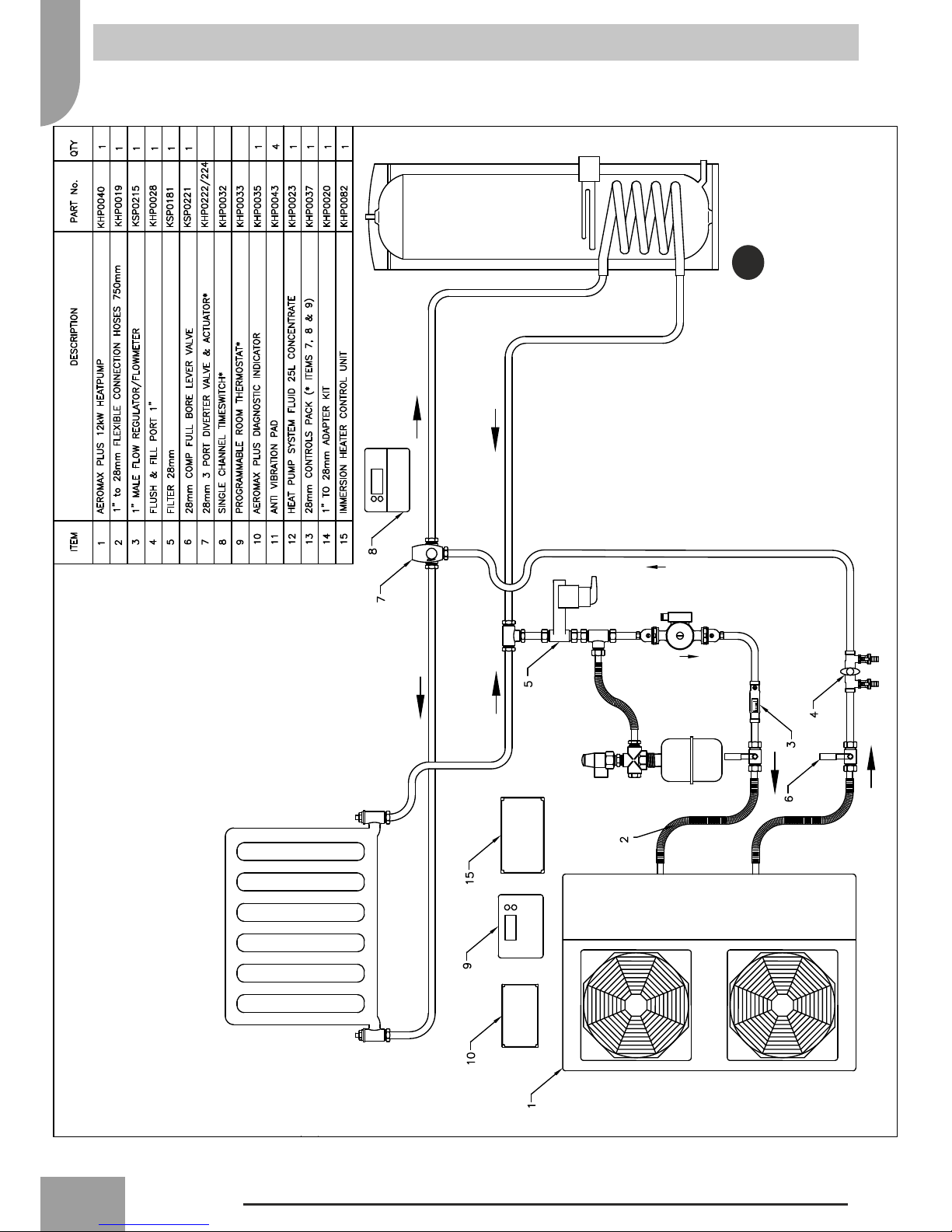
Recommended water diagram (Fig. 9)
Typical water circuit diagram for Aeromax Plus unit
(see fig. 9)
1 Isolating valves
2 System filter
3 Expansion vessel with PRV & Gauge (Robokit)*
4 Flush & Fill Ports
5 System drain valve (at lowest point ofsystem)*
6 Air purge (at highest points ofsystem)*
7 3-way valve
8 Hot water cylinder
9 Heating system
10 Circulating pump with isolating valves*
11 Flowmeter/setter
*not included in installers pack
% Inhibited Propyl-
ene Glycol
10% 20% 30% 40%
Freezing time (*) -4 °C -9 °C -15 °C -23°C
Correction
Factors
Capacity 0,996 0,991 0,983 0,974
Absorbed power 0,990 0,978 0,964 1,008
Loss ofhead 1,003 1,010 1,020 1,033
(*) Note: Temperature values are indicative.
Always refer to the temperatures indicated for the specific product used
TABLE TO USE FOR CALCULATING THE WATER CONTENT IN THE SYSTEM
Installed Unit .............
Unit content (*) l .............
Pipe content (**) l .............
Uses (fan-coil, panels, radiators, etc.) (***) l .............
Total content (****) l .............
(*) Consult the technical data table.
(**) Consult the pipe water content table.
(***) Consult the manual from the relevant manufacturer.
(****) The water content ofthe system must be greater than the minimum value for units without hydronic kit. The minimum
value is necessary to provide optimal comfort.
Detailed installation schematics can be found at the back ofthe manual.
Should you require further technical assistance call your local office – details on the back page of this manual.
Do not use the heat pump to treat industrial process, swimming pool or sanitary water. In all these
cases, provide an intermediate heat exchanger.
9
11
16
If the system details are outside ofthe range shown in
the table the expansion vessel size can be calculated
using the following formula:
V = e * C / {1-[ (Ppre + 1)/(Pmax + 1) ] }
Where:
e = Coefficient of Fluid Expansion with respect to 10°C
(30% Glycol/Water)
C = total System Volume (litres).
Ppre = Pre-charge Pressure (Bar)
Pmax = Max System Pressure (Bar)
Maximum Working Temperature
30 40 50 60 70 80 90
Coefficient of Fluid Expansion with respect to 10°C (30% Glycol/
Water)
0.00272 0.00499 0.00779 0.01108 0.0148 0.01891 0.02336
Pre-charge
Pressure
(Air side ofvessel)
Max System Pressure
(Pressure ReliefValve
Rating)
System
Volume
(Litres)
Approximate Expansion Vessel Volume Required (Litres) as a
Function ofthe Max Working Temperature
0.5 1 100 1.1 2 3.1 4.4 5.9 7.6 9.3
0.5 1.5 100 0.7 1.2 1.9 2.8 3.7 4.7 5.8
0.5 2 100 0.5 1 1.6 2.2 3 3.8 4.7
0.5 2.5 100 0.5 0.9 1.4 1.9 2.6 3.3 4.1
1 1.5 300 4.1 7.5 11.7 16.6 22.2 28.4 35
1 2 300 2.5 4.5 7 10 13.3 17 21
1 2.5 300 1.9 3.5 5.5 7.8 10.4 13.2 16.4
1 3 300 1.6 3 4.7 6.6 8.9 11.3 14
1.5 2 500 8.2 15 23.4 33.2 44.4 56.7 70.1
1.5 2.5 500 4.8 8.7 13.6 19.4 25.9 33.1 40.9
1.5 3 500 3.6 6.6 10.4 14.8 19.7 25.2 31.2
2 2.5 1000 19.1 34.9 54.5 77.5 103.6 132.4 163.5
2 3 1000 10.9 19.9 31.2 44.3 59.2 75.7 93.5
Aeromax Plus Expansion Vessel Sizing – Sizing Examples
Note: the required vessel volume will almost certainly
not correspond exactly to an existing size, therefore the
nearest available size above the value returned for V
must be selected from the available vessels in the
range.
The calculation is valid provided the expansion vessel
and the safety valve are at the same height. The
maximum system pressure for Aeromax Plus Heat
Pumps is 3 bar.
Cylinder Installation for Domestic Hot Water
We recommend the Kingspan Albion Aerocyl is used as it
has a heat pump specific coil fitted.
!Note...
Ifthe Aerocyl is used in conjunction with the 3 port valve
supplied with the Aeromax plus there is no requirement for
the additional 2 port valve.

17
Water connections (Typical Schematic for Radiator System)
4, 6 & 8 kW
No 2 port
required if
using with
heat pump
NOTE
18
Water connections (Typical Schematic for Radiator System)
No 2 port
required if
using with
heat pump
NOTE
12 kW

19
Water connections (Typical Schematic for Radiator System)
15 kW
No 2 port
required if
using with
heat pump
NOTE
20
Electrical connections (Fig. 13)
!All field electrical connections are the responsibility of the installer.
!WARNING
Make water connections before electrical connections. Make ground connection prior to any other electrical
connections.
Unit Aeromax Plus
KHP041 KHP0038 KHP0039 KHP0040 KHP0042
4kW 6kW 8kW 12kW 15kW
Power Supply V - ph - Hz 230 - 1 - 50
Allowable Voltage Range V 207/253
Maximum Power Drawn kW 2 2.3 2.7 5.1 5.1
Maximum Current Drawn A 7.2 11 14 23 20
Power Fuses Type gL Type
Current (A) 10 Type B 15 Type B 15 Type B 25 Type D 25 Type D
Power Supply Cables mm2 H07RN-F 3 x 2.5mm2
Maximum Circulating Pump Current A 2
Use cables H03VV-F 4x0.75 mm² to connect the control to
wire User Comfort Interface (KHP0008)
Cables from Indoors – Heat Pump
2x 3 core 240v
1x 7 core for 0-12v
1x 3 core mains to HP
Wired control For installation of wired remote controller please refer to the control installation manual.
Power supply Size the cable, the cables must be H07RN-F type (3 x 2.5 mm2).
According to the installation instructions, all devices for disconnection from the power supply
mains must have a contact opening (4 mm) to allow total disconnection according to the
conditions provided for the overvoltage class III.
To prevent any risk, the power cable must only be replaced by the technicians ofthe after-sales
service.
Remove the front panel, the electric parts appear at the
front side. The power supply cables can be inserted into
the holders. Be sure to fix the power cable with bundling
band sold on the market so that they do not make contact
with the compressor and the hot pipes.
To ensure good tensile strength, the electric cables must
be fastened using the cable-holder on the plate.
The unit can be controlled and set via:
• User Comfort Interface wire control KHP0008
(Optional)
• Aeromax Plus Controls Pack KHP0036/37
• Switches (not supplied)
For the electrical connections refer to wiring diagram,
while, for use, refer to the relative manuals.
Only for KHP0042 use the strain reliefsupplied with the
unit.
This manual suits for next models
9
Table of contents
Popular Heat Pump manuals by other brands


Airwell
Airwell CKD Series Service manual

Carrier
Carrier 50YQ Installation, Start-Up and Service Instructions

Mitsubishi
Mitsubishi ESA30EH2-25 Technical manual

Nibe
Nibe F1255 Series user manual

STIEBEL ELTRON
STIEBEL ELTRON HPA-O 4 CS Plus Operation and installation instruction

Nibe
Nibe FIGHTER 1310 Installation and maintenance instructions