AEROPOWER Powersky X6 User manual

WWW.AEROPOWER.COM.TW© 2019 ALL RIGHTS RESERVED.
A E R O P OW E R V E NTI L A T I O N CO. , L T D
INSTALLATION
GUIDE
Powersky○
RX6

WWW.AEROPOWER.COM.TW© 2019 ALL RIGHTS RESERVED.
HARDWARE
The fan hardware that suspends the fan and the wing is located on the hardware kit. Before installing,
ensure you have the following hardware.
Installation Hardware Kit 1
Upper Yoke Hardware
Extension Tube Hardware
Lower Yoke Hardware
Main Fan Unit Hardware
•(4) M12 x 50 MM Bolt
•(8) M12 Flat Washer
•(4) M12 Nylock Nut
•Shackle
•(2) M16 x 120 MM Bolt
•(4) M16 Flat Washer
•(2) M16 Nylock Nut
•(2) M16 x 120 MM Bolt
•(4) M16 Flat Washer
•(2) M16 Nylock Nut
•(4) M12 x 25 MM Bolt
•(8) M12 Flat Washer
•(4) M12 Nylock Nut
Airfoil And Winglet Hardware Kit
Airfoil Hardware
Winglet Hardware
Guy Wire 2
•(12) M10 x 50 MM Bolt
•(24) M10 Flat Washer
•(12) M10 Nylock Nut
•(24) M4 Flat Washer
•(24) M4 x 10 MM Bolt
•(4) Locking Carabiner
•(4) 10MM Beam Clamp
•(4) M10 X 25MM Eyebolt
•(4) M10 Nylock Nut
•(4) Gripples
•(4) Guy Wire
1. Square washers are included and are only used when the fan is mounted to the angle iron. The number of square washers required depends on the number of angle
irons used.
2. The guy wire is only supplied when it is necessary to limit the fan shake. If the extension tube is 4 ft (1.2 meters) or longer, the fan is susceptible to strong winds or the
like or the fan is close to the building structure. Aero Power Solutions recommends the use of guy wire.
Parts
Check that you have all the necessary parts before installation. If you order multiple fans, be sure to classify
the components of each fan separately. Each fan has different grades and is not interchangeable.
(2) Beam Clips Upper Yoke2 Lower Yoke Hub Cover Main Fan Unit
(2) Spacers1
Airfoil Winglet Airfoil Retainer Extension Tube3Controller
1. Spacers are only used if the beam flange exceeds 3/8” (10 mm).
2. Ensure you have the correct upper yoke for your mounting method. The upper yoke may differ from
the illustration.
3. Safety cable is attached to extension tube.
WWW.AEROPOWER.COM.TW© 2019 ALL RIGHTS RESERVED.
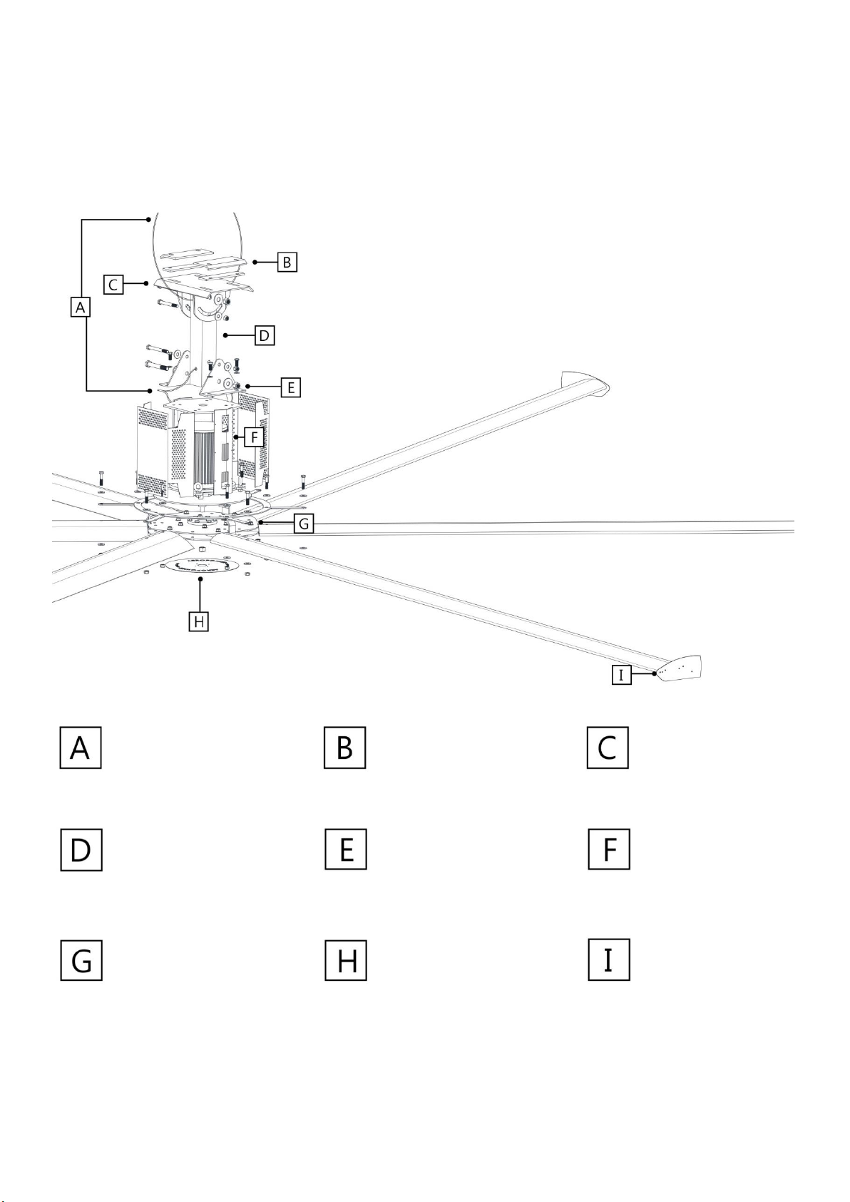
DECOMPOSITION
If you lose any parts or hardware required for installation, please contact customer service.
1. Used only if mounting fan to an I-beam. Spacers are used only when the I-beam flange exceeds 3/8”(10 mm).
Safety Cable
Beam Clips1
Spacers1
Upper Yoke
Extension Tube
Lower Yoke
Main Fan Unit
Hub
Hub Cover
Winglets

WWW.AEROPOWER.COM.TW© 2019 ALL RIGHTS RESERVED.
INSTALLATION LOCATION
Before installation, confirm the following requirements to check that the building structure and fan location
are in compliance with Aero Power Solutions' safety guidelines.
☐If the fan's extension boom is 4 inches (1.2 meters) or longer or the installation structure requires, the
cable must be used to limit fan shake. If the fan is close to any building equipment, Aero Power Solutions
recommends fixing the fan with a cable to ensure safety.
☐When installing the fan, the fan must be perpendicular to the ground.
☐The distance between all fan parts and obstacles is ≥2 ft (61 cm). No obstacles such as lights, cables,
sprinklers or other structural components are allowed in the fan installation area.。
Net space distance guide
If fan usage does not meet these requirements, please contact customer service to discuss other fan
installations or select other fans.
General spacing
☐The distance between the center of the fan must not be less than 2.5x the diameter of the fan.
☐When installing the fan, the fan must be at least 10 ft (3 meters) above the floor.
Ceiling pitch
Depending on the fan size, the fan must be installed at the following distances. The distance between the fan
and the ceiling is the distance between the top of the winglet and the ceiling.
Powersky®X6
Fan diameter
Distance from the ceiling
10 ft(3.0 meters)
4 ft(1.2 meters)
13 ft(4.0 meters)
5 ft(1.5 meters)
16 ft(4.9 meters)
6 ft(1.8 meters)
WWW.AEROPOWER.COM.TW© 2019 ALL RIGHTS RESERVED.
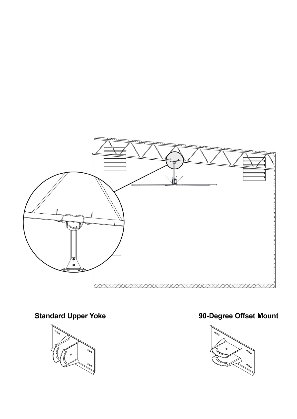
Understanding roof pitch
To ensure the fan is properly mounted, the fan must always hang plumb to the ground and the yoke must be
installed using the bolt holes at the widest locations possible. To accommodate building structures on which
the standard upper yoke does not allow the fan to properly orient itself, the 90-Degree Offset mount should
be purchased.
The example below shows one situation in which the 90-Degree Offset mount must be used so that the fan
hangs plumb to the ground and the widest stance for the upper yoke is ensured. If you are uncertain of your
roof pitch or do not have the correct mount to properly hang your fan, consult a structural engineer or contact
Aero Power Fans Customer Service.
WWW.AEROPOWER.COM.TW© 2019 ALL RIGHTS RESERVED.
Pre-Installation
Mechanical installation
•A 16-ft (4.9-m) Powersky®X6 fan weighs, at maximum, 275 lbs (125 kg). A suitable means for lifting the
weight of the fan, such as a scissor lift, and at least two (2) installation personnel will be required.
•Aero Power Fan can only be mounted to an I-beam or angle irons. If mounting to an I-beam, the I-beam
must be part of the existing building structure. Do not mount the fan to a single purlin, truss, or bar joist.
Consult a structural engineer for installation methods not covered in the guide.
•The mounting structure must be able to withstand the torque forces generated by the fan.
•Fans mounted on fabricated I-beams, which are common in steel buildings, could cause the beam to flex
and the fan to move significantly during operation. If this flexing causes a clearance problem, we suggest
installing the I-Beam Stabilizer kit.
•If the fan’s extension tube is 4 ft (1.2 m) or longer or if the mounting structure requires it, the fan’s lateral
movement must be secured using guy wires. If the fan is close to any building fixtures it is recommended
to secure the fan with guy wires as a safety measure.
•Adhere to the safety requirements in the table below when selecting where to mount the fan.
Safety requirement
Minimum distances
Clearance
≥2 ft from all fan parts. The fan installation area must be free of obstructions such as lights, cables,
sprinklers, or other building structure. See the tables on pp. 2–3 for recommended minimum ceiling
clearances.
Airfoil height
≥10 ft above the floor
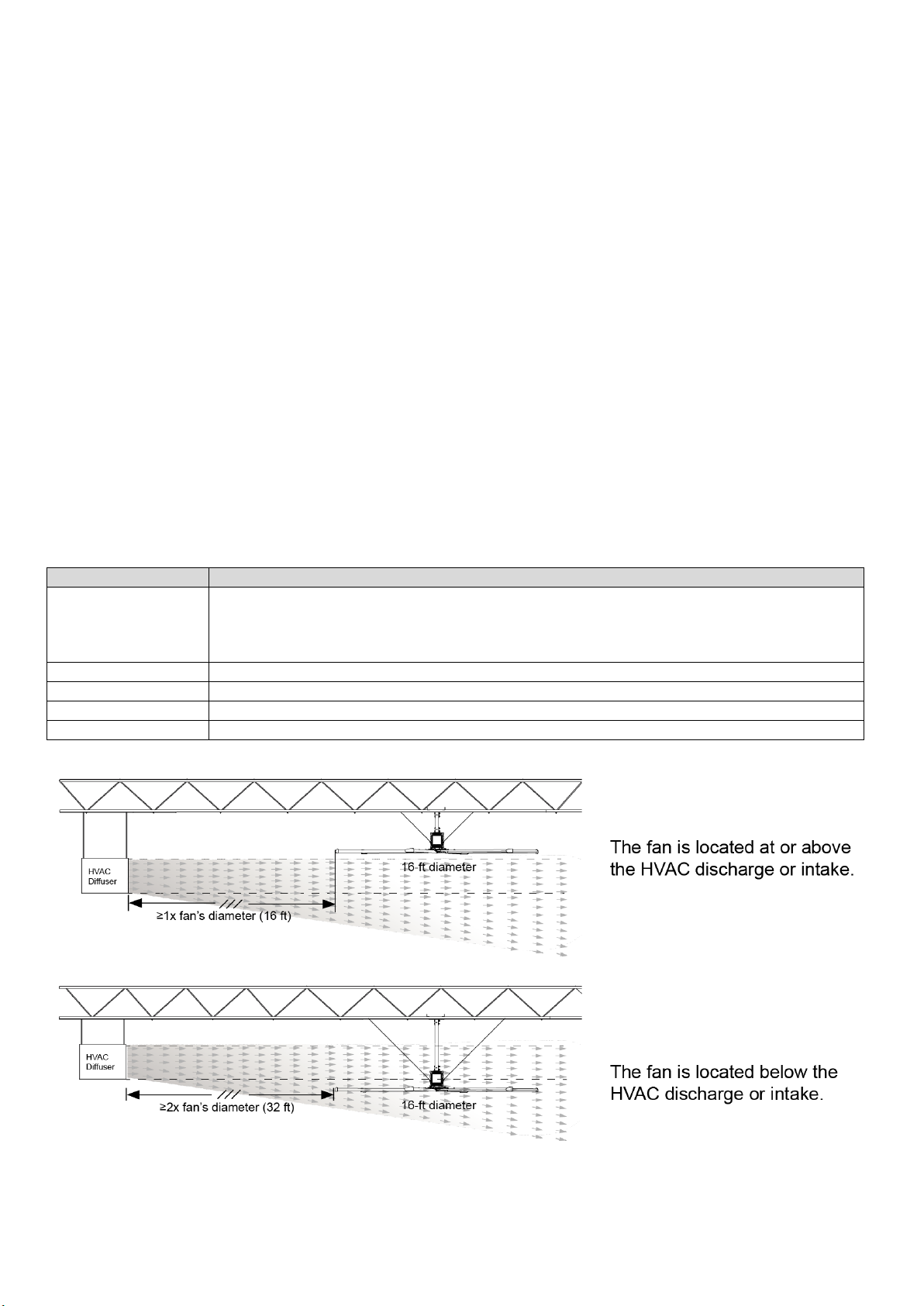
HVAC equipment
≥1x fan diameter if above diffuser. ≥2x fan diameter if below diffuser. Refer to the illustration below.
Fan spacing
2.5x fan diameter, center-to-center
Radiant/IR heaters
See the manufacturer’s requirements for the minimum clearance to combustibles.
WWW.AEROPOWER.COM.TW© 2019 ALL RIGHTS RESERVED.
INSTALLATION
WARNING:The fan cannot be installed unless the structure of the installed fan is strong, undamaged,
and can support the load and installation method of the fan. Structural engineers should verify that the
structure is appropriate before installing the fan. The customer and/or end user is solely responsible for
confirming the stability of the installation structure.
Aero Power Solutions hereby expressly disclaims any liability, or do not use Aero Power Solutions to
provide or install any of the materials or hardware described in the instructions.
NOTICE:Before installation, make sure you have a upper yoke that fits the slope of the roof.
WARNING:Make sure there are no people under the fan during installation!
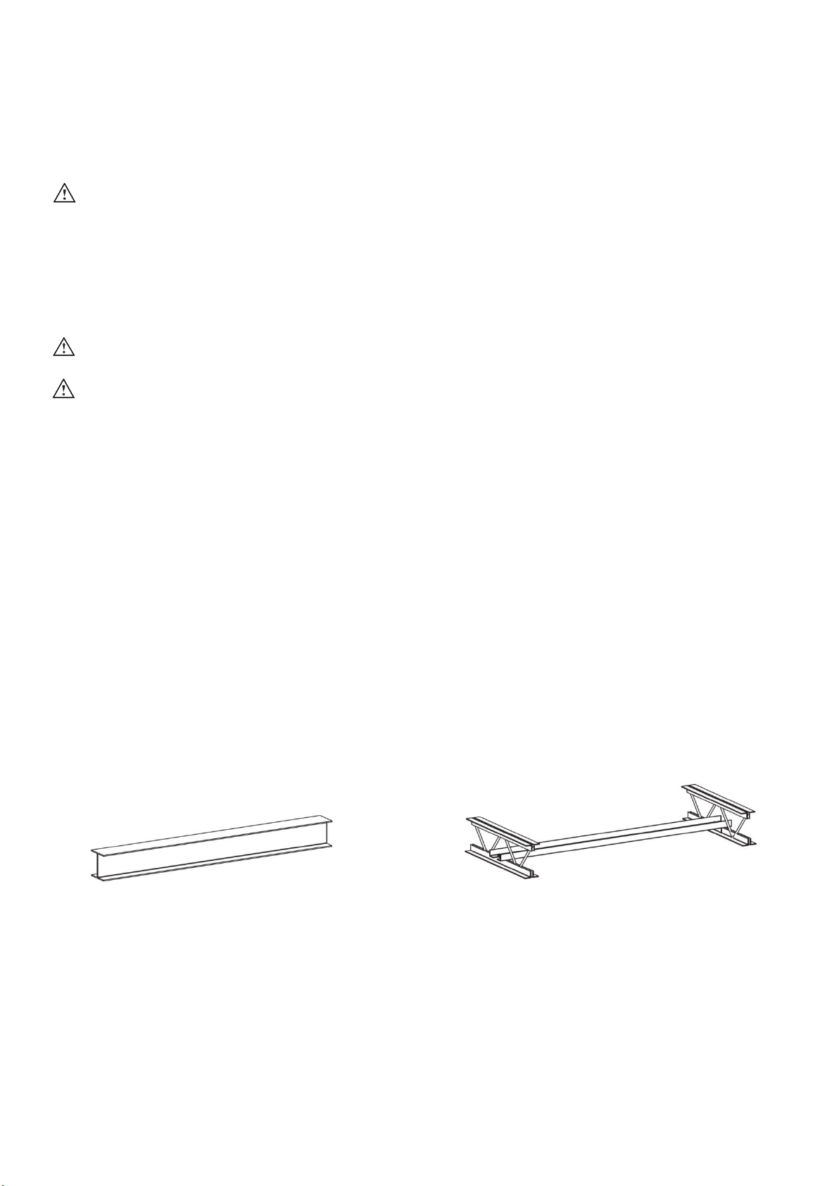
Overview
PowerSky X6 can only be hung from I-beams or bar joists. For structural installation methods not covered in
this manual, please consult a structural engineer.
I-Beam
•It is not recommended to install the fan on the
prefabricated I-beam.
•Do not install the fan directly on the I-beam.
•The I-beam must be part of the existing building
structure.
Angle Iron
•Do not install a fan from a single purlin, truss or
bar joists.
•The unsupported angle iron span should not
exceed 3.7 meters.
•The angle iron must be fixed to the roof structure
at each end.

WWW.AEROPOWER.COM.TW© 2019 ALL RIGHTS RESERVED.
1a. Prepare The I-beam
NOTICE
If you install the fan on the angle iron, continue reading the next page.
Measure the width of the beam edge of the suspended fan. Select the mounting hole that matches the width
of the I-beam as shown in the figure below.
Continue with step 2.
Small upper yoke
13-3/4 inches x10 inches
(349 mm x 258 mm)
I-beam width
5 inches to 9-7/8 inches
(127 至250 mm)
Large upper yoke
18-1/2 inches x10 inches
(470 mm x 258 mm)
I-beam width
9-7/8 inches to 14-5/8 inches
(250 至371 mm)

WWW.AEROPOWER.COM.TW© 2019 ALL RIGHTS RESERVED.
1b.Prepare Angle Irons
WARNING:Do not install a fan from a single purlin, truss or bar joists.
WARNING:The unsupported angle iron span should not exceed 12 ft (3.7 meters).
WARNING:Angle iron must be fixed to the roof structure at each end.
For mounting the fan on the I-beam, see the previous page. For structural installation methods not covered
in this manual, please consult the structural engineer.
A. Select proper angle irons
Using the table and diagrams below, select the proper angle irons for fan installation.
Note: Angle irons and angle iron hardware are not included with the fan.
Angle iron span
(Between installation points)
Minimum angle iron size
(Width X Height X Thickness)
Number of angle irons
required
6 ft(1.8 m)or less
2.5”x2.5”x0.25”
(6.4 cmx 6.4 cm x 0.6 cm)
2
6 ft to 8 ft(1.8 m to 2.4 m)
3”x3”x0.25”
(7.6 cm x 7.6 cm x 0.6 cm)
2
8 ft to12 ft(2.4 m to 3.7 m)
3”x3”x0.25”
(7.6 cm x 7.6 cm x 0.6 cm)
4*
*Two pairs of angle irons. Pairs should be placed back to back and fastened in center
WWW.AEROPOWER.COM.TW© 2019 ALL RIGHTS RESERVED.
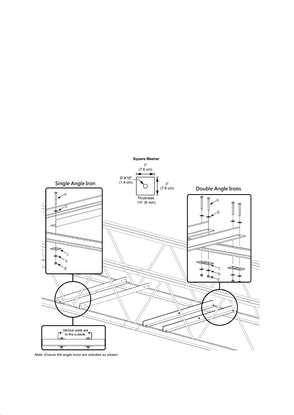
B. Fasten angle irons to roof structure mounting points
Fasten the angle irons to the roof structure mounting points at each end with Grade 8 hardware. Do
not fully tighten the hardware.
Single Angle Iron
Position the angle irons so that the horizontal legs
face each other (vertical legs are on the outside).
Double Angle Irons
Position the angle irons with fan mounting holes on
the inside, facing each other.
Grade 8 Angle Iron Hardware (Installer-Supplied):
a. (4 or 8) M12 GR 8 Bolt
b. (8 or 16) M12 GR 8 Washer
c. (4 or 8) 2”x 3”(51 x 76 mm) Rectangular Washer (APF-supplied; see diagram)
d. (4 or 8) M12 GR 8 Nylock Nut
WWW.AEROPOWER.COM.TW© 2019 ALL RIGHTS RESERVED.
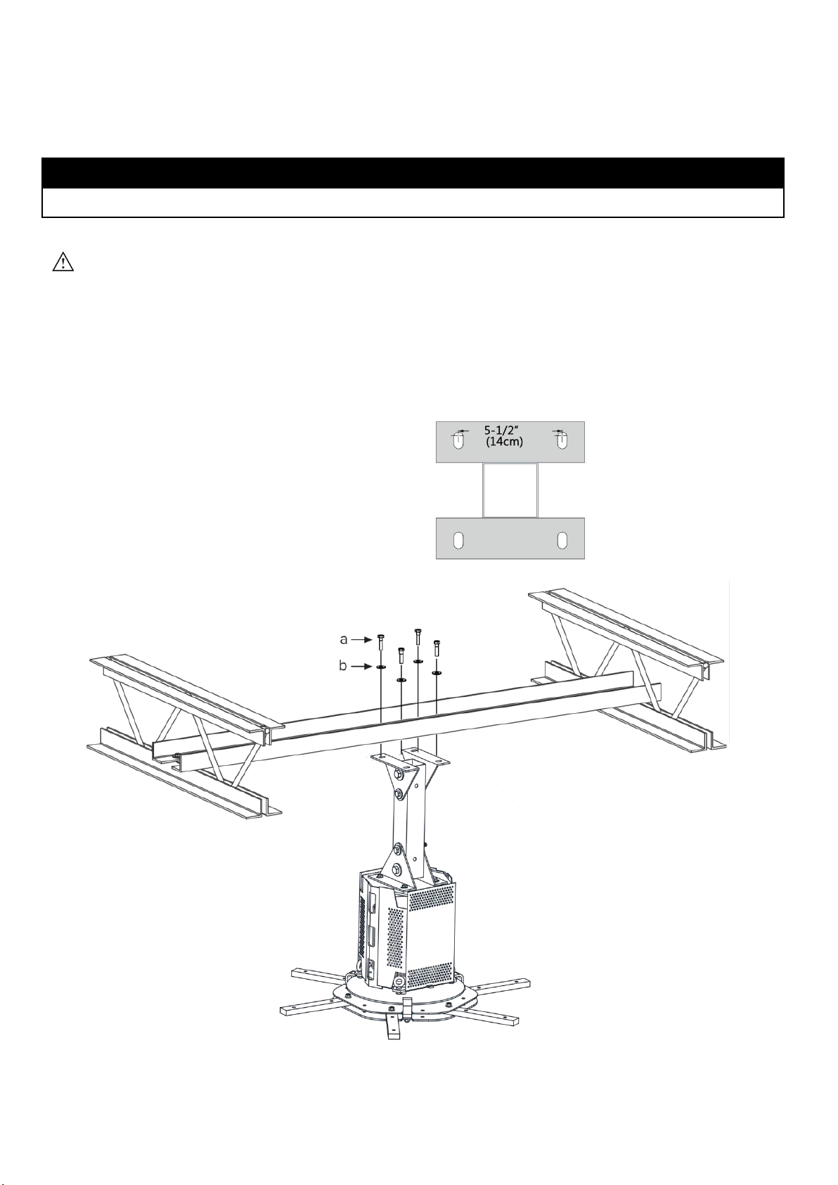
2. Install The Main Fan Unit On The Angle Iron
注意
NOTICE
If using the extension tube to install the fan, skip to step 3a (I-beam) or 3b (angle iron).
CAUTION: The main fan unit is heavy. Use caution when raising it.
Use the fan main assembly kit to secure the fan main unit directly to the angle iron. The distance between
the angle irons is shown in the figure below.
After fixing the main fan part to the angle iron, fix the angle iron to the roof structure.
Proceed to 5.Secure Upper Safety Cable
Main Fan Unit Hardware(APF-Supplied):
a. (4) M12 GR 8 Bolt
b. (8) M12 GR 8 Washer
c. (4) M12 GR 8 Nylock Nut

WWW.AEROPOWER.COM.TW© 2019 ALL RIGHTS RESERVED.
3a.Install Upper Yoke Fixing On The I-beam注意
NOTICE
If you are installing the fan on the angle iron, skip step 3b on the next page.
Measure the flange width of the I-beam from which the fan will be hung. Select the upper yoke mounting
holes that match the flange width of the I-beam.
Secure the upper yoke to the I-beam using the upper yoke hardware kit.
Proceed to 4.Installation Extension Tube
Upper Yoke Hardware(APF-Supplied):
a. (4) M12 X 55 MM GR 12 Bolt
b. (8) M12 Flat Washer
c. (4) M12 Nylock Nut
d. (2) Beam Clip
e. (2) Spacer

WWW.AEROPOWER.COM.TW© 2019 ALL RIGHTS RESERVED.
3b. Attach Upper Yoke (To Angle Irons)
Secure the upper yoke directly to the angle irons with the Upper Yoke Hardware as shown.
Upper Yoke Hardware (APF-Supplied):
a. (4) M12 X 50 MM GR 8 Bolt
b. (8) M12 Flat Washer
c. (4) M12 Nylock Nut
The angle irons should be aligned with the outermost holes on the upper yoke. Do not use beam
clips on angle irons!
WWW.AEROPOWER.COM.TW© 2019 ALL RIGHTS RESERVED.
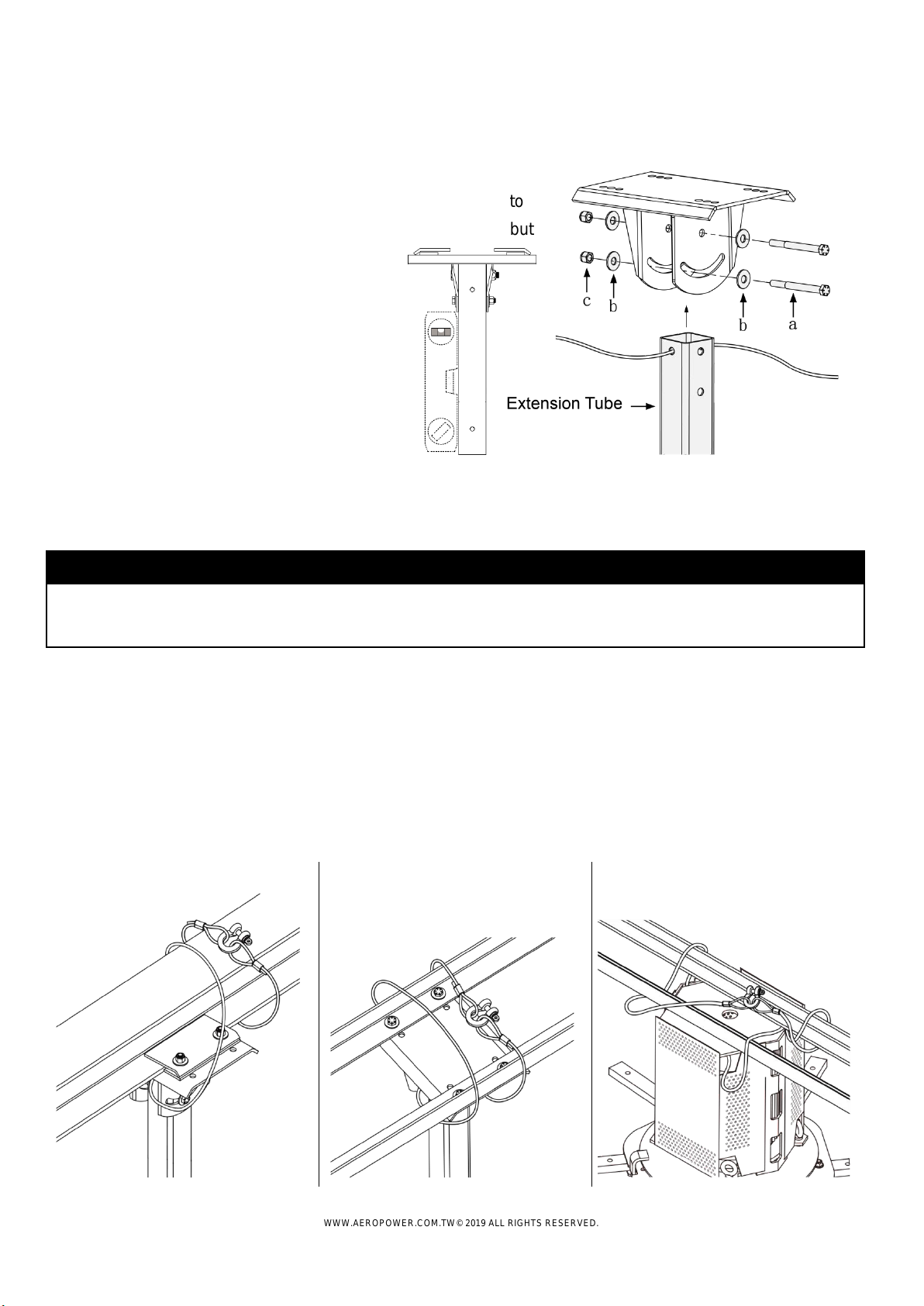
4. Attach Extension Tube (To Upper Yoke)
Secure the extension tube to the upper yoke using the extended
tube hardware. Ensure the extension tube is hanging plumb to
the ground, and then tighten the hardware so that it is snug, but
not fully tightened.
Extension Tube Hardware (APF-Supplied):
a. (2) M16 x 120 MM GR 8 Bolt
b. (4) M16 Flat Washer
c. (2) M16 Nylock Nut
5. Secure Upper Safety Cable
NOTICE
The safety cable is a crucial part of the fan and must be installed correctly. If you have questions
or require assistance, call Customer Service for assistance.
Note: If the fan installation contains an extension tube, the safety cable is pre-connected to the extension
tube. If the fan without an extension tube is installed, the safety cable is individually packaged.
Wrap the safety cable around the mounting structure and secure the looped ends with the shackle as shown.
The cable must be drawn tightly around the I-beam or angle iron, leaving as little slack as possible. The
shackle should be on the topside of the I-beam or angle iron if possible. Securely tighten the shackle.
I-Beam Mount
Angle Iron Mount
Direct Mount

WWW.AEROPOWER.COM.TW© 2019 ALL RIGHTS RESERVED.
6. Attach Lower Yoke (To Extension Tube)
Attach the lower yoke to the bottom of the extension tube with the
Lower Yoke Hardware as shown.
Tighten the hardware so that it is snug, but not fully tightened.
Lower Yoke Hardware (APF-Supplied):
a. (2) M16 x 120 MM GR 8 Bolt
b. (4) M16 Flat Washer
c. (2) M16 Nylock Nut
7. Attach Main Fan Unit (To Lower Yoke)
CAUTION: The main fan unit is heavy. Use caution when raising it.
Attach the main fan unit to the lower yoke with the Main Fan Unit
Hardware as shown. Do not rest the main fan unit on the ground!
Make sure the lower cable is positioned between the lower yoke
brackets as shown on the right.
Main Fan Unit Hardware (APF-Supplied):
a. (4) M12 x 30 MM GR 8 Bolt
b. (8) M12 Flat Washer
c. (4) M12 Nylock Nut
WWW.AEROPOWER.COM.TW© 2019 ALL RIGHTS RESERVED.
8. Confirm Orientation
After securing the main fan unit to the lower yoke, allow the fan to hang so
that the extension tube is plumb to the ground. When it is properly positioned,
fully tighten the mounting hardware (Lower Yoke Hardware and Extension
Tube Hardware).
9. Installing Guy Wires
注意
NOTICE
Guy wires may not be included in your fan order. They are intended to constrain the fan’s lateral movement
and are only included with fans that have extension tubes 4 ft (1.2 m) or greater in length. Depending on
the conditions at the installation site, guy wires may be needed for fans with shorter tubes to prevent any
lateral movement. If guy wires are needed and were not included with your fan order, contact Aero Power
Customer Service.
WARNING : Ensure power is disconnected from the fan before installing the guy wires.
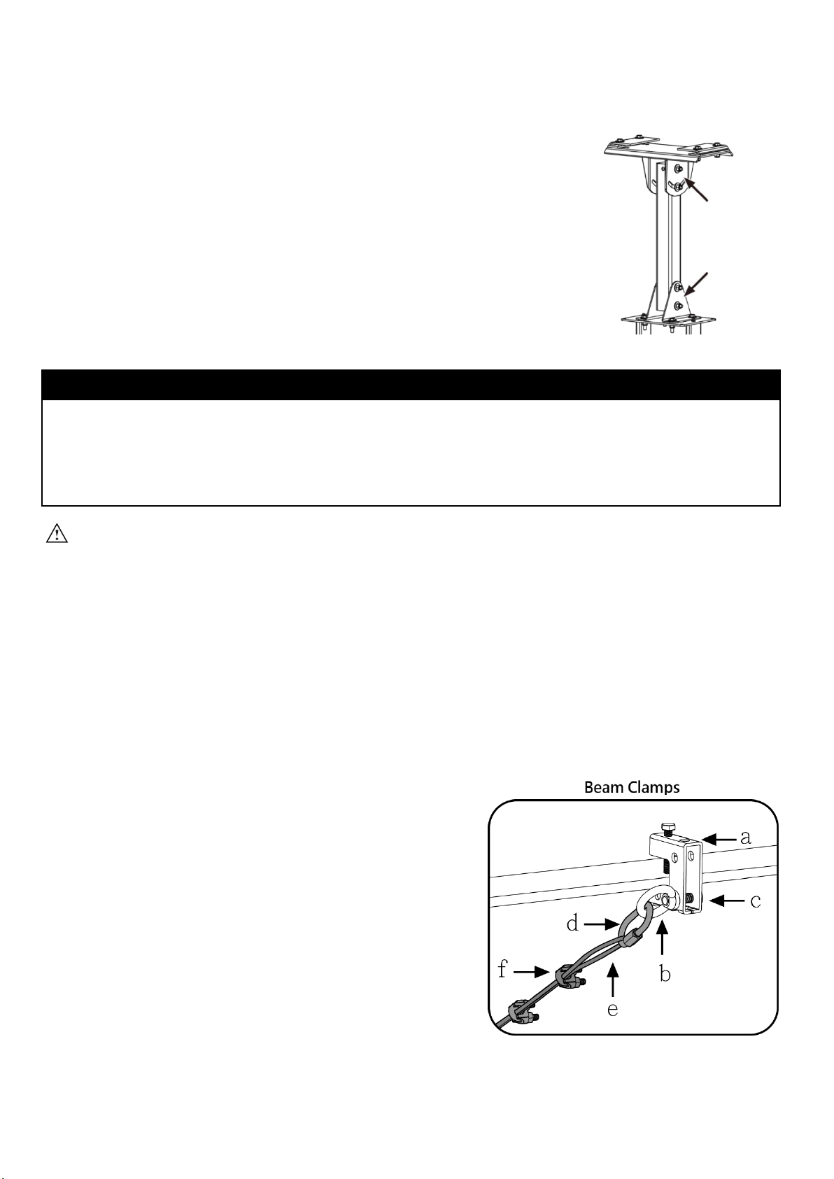
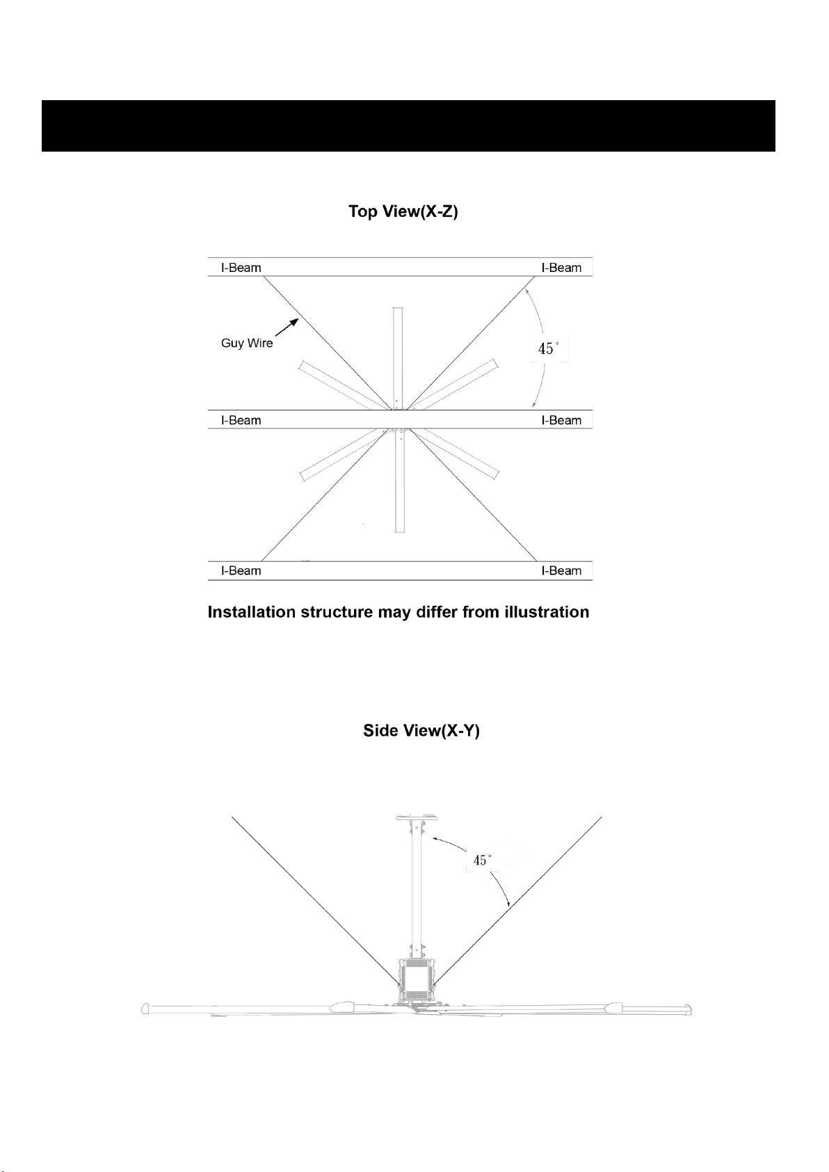
A. Attach beam clamp
Attach the beam clamp to the mounting structure. The guy wire should
be approximately 45°from the horizontal plane. Place the beam clamp
accordingly. Refer to the illustrations on the following page. Fully tighten
the set screw to secure the clamp.
Fasten the small eyebolt and nut onto the beam clamp. The nut will be
on the outside of the beam clamp.
Loop the crimped end of the guy wire into the locking carabiner and
secure to the eyebolt as shown. Securely tighten the carabiner.
Guy Wire Hardware (APF-Supplied):
a. (4) 8MM Beam Clamp
b. (4) M10 X 15 MM Eyebolt
c. (4) M10 x 35 MM Bolt
d. (4) Locking Carabiner
e. (4) Guy Wire
f . (4) Wire Rope Clip
WWW.AEROPOWER.COM.TW© 2019 ALL RIGHTS RESERVED.
For best results, the guy wires should be installed at 45°in the X-Y, Y-Z, and X-Z planes as shown
below. If the angle deviates by more than 15°, contact Customer Service for assistance.

WWW.AEROPOWER.COM.TW© 2019 ALL RIGHTS RESERVED.
B. Route guy wires through Gripples
Route each guy wire through a Gripple and a eyebolt on the fan, and then back through the Gripple. Do not
tighten the Gripples until all guy wires have been installed.
C. Secure guy wires
WARNING:Over-tightening the guy wires could throw the fan off balance.
Repeat step B to install the remaining three guy wires.
Evenly cinch all four guy wires into place using the Gripples. The guy wires should be taut, evenly spaced
around the fan, and away from the path of the airfoils. Maintain a distance of 6”to 8”(152 to 203 mm)
between the Gripples and the carabiners.
Once all of theguy wires are taut and correctlypositioned, secure their loose ends with the wire rope clips and
tighten. Ensure all electrical cords/cables are unobstructed by the guy wire system.
WWW.AEROPOWER.COM.TW© 2019 ALL RIGHTS RESERVED.
10. Install Airfoils
A. Attach winglets to airfoils
NOTE : Examine each airfoil to ensure the winglets is still securely attached before proceeding.
Attach a winglet to each airfoil with the Winglet Hardware. Secure winglets to all airfoils before attaching
the airfoils to the fan.
Winglet Hardware(APF-Supplied):
a. (6) M8 X 25MM Bolt
b. (6) M8 Spring Washer
c. (6) M8 Long Nut
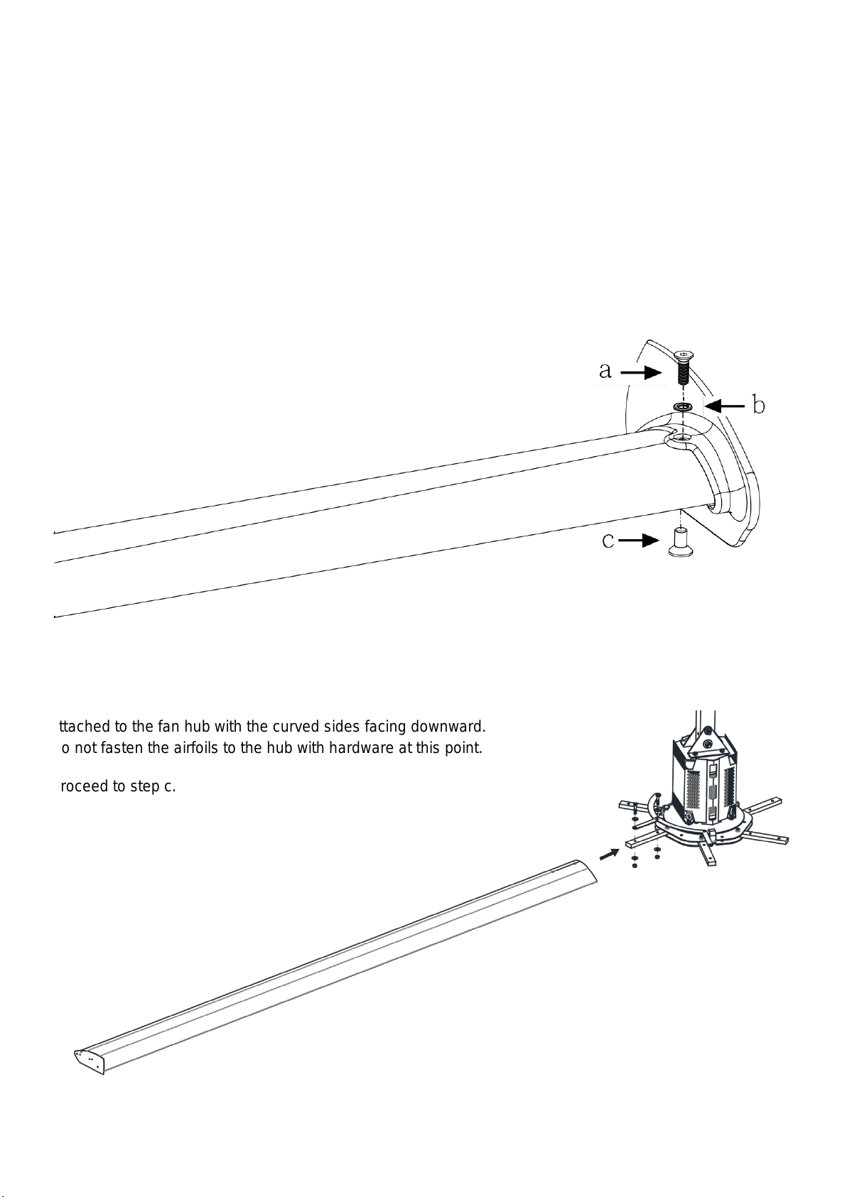
B. Secure airfoils to hub
Slide the airfoils onto the tabs of the fan hub. The airfoils must be
attached to the fan hub with the curved sides facing downward.
Do not fasten the airfoils to the hub with hardware at this point.
Proceed to step c.

WWW.AEROPOWER.COM.TW© 2019 ALL RIGHTS RESERVED.
C. Attach airfoils to hub
Attach the 6airfoilretainers with the Airfoil Hardware. Moving clockwise around the fan hub, positionthe airfoil
retainers end over end as shown. Hole A of the retainer should be positioned over top of Hole B. Do not
tighten the bolts until all the airfoil retainers have been attached!
Airfoil Hardware (APF-Supplied):
a. (12) M10 x 50 MM GR 8 Bolt
b. (48) M10 Flat Washer
c. (12) M10 Nylock Nut
11. Install Hub Cover
Secure the hub cover to the fan hub with the Hub Cover Hardware.
Hub Cover Hardware(APF-Supplied):
a. (4) M4 Bolt
Table of contents
Popular Fan manuals by other brands

Movex
Movex FB Series installation instructions

Activejet
Activejet Action Selected WKS-120CPJ OPERATING MANUAL & WARRANTY

Emerson
Emerson SUMMERHAVEN CF850GES00 owner's manual

Hunter
Hunter Type 3 Models Owners and installation manual

Westinghouse
Westinghouse 73040 instruction manual

Craftmade
Craftmade Quest CQ52 Specifications


Ruck Ventilatoren
Ruck Ventilatoren EM 100L EC 02 Assembly instruction

Varma
Varma FS40-16JA instruction manual

Kichler Lighting
Kichler Lighting Wilton instruction manual

Ventamatic
Ventamatic HVPF 30 WM owner's manual

impress
impress IM-709V manual

Somogyi Elektronic
Somogyi Elektronic Home SFE 41/BK instruction manual