Aerotech NPAQ MR User manual

P/N:EDU210
Revision: 1.06.00
Npaq MRHardware Manual
AEROTECH.COM
ON
OFF
Npaq MR
FEEDBACK COMMUNICATIONS
1 2 3 4 5 6 7 8
1 2 3 4 5 6 7 8
1 2 3 4 5 6 7 8
1 2 3 4 5 6 7 8
EXT DRIVE RS232
AUX ENCODER
JOYSTICK
ESTOPMOTOR
DIGITAL / ANALOG IO

Global Technical Support
Go to www.aerotech.com/global-technical-support for information and support about your Aerotech products. The website
provides downloadable resources (such as up-to-date software, product manuals, and Help files), training schedules, and PC-
to-PC remote technical support. You can also complete Product Return (RMA) forms and get information about repairs and
spare or replacement parts. For immediate help, contact a service office or your sales representative. Have your customer
order number available before you call or include it in your email.
United States (World Headquarters)
Phone: +1-412-967-6440
Fax: +1-412-967-6870
Email: service@aerotech.com
101 Zeta Drive
Pittsburgh, PA 15238-2897
www.aerotech.com
United Kingdom Japan
Phone: +44 (0)1256 855055
Fax: +44 (0)1256 855649
Email: service@aerotech.co.uk
Phone: +81 (0)50 5830 6814
Fax: +81 (0)43 306 3773
Email: service@aerotechkk.com.jp
Germany China
Phone: +49 (0)911 967 9370
Fax: +49 (0)911 967 93720
Email: service@aerotechgmbh.de
Phone: +86 (21) 3319 7715
Email: saleschina@aerotech.com
France Taiwan
Phone: +33 1 64 93 58 67
Email: sales@aerotech.co.uk
Phone: +886 (0)2 8751 6690
Email: service@aerotech.tw
This manual contains proprietary information and may not be reproduced, disclosed, or used in whole or in part without the
express written permission of Aerotech, Inc. Product names mentioned herein are used for identification purposes only and
may be trademarks of their respective companies.
Copyright © 2009-2016, Aerotech, Inc. All rights reserved.

Table of Contents Npaq MR Hardware Manual
Table of Contents
Table of Contents iii
List of Figures v
List of Tables vi
EC Declaration of Conformity vii
Agency Approvals viii
Safety Procedures and Warnings ix
Quick Installation Guide xi
Chapter 1: Introduction 1
1.1. Electrical Specifications 4
1.1.1. System Power Requirements 7
1.2. Mechanical Specifications 8
1.3. Environmental Specifications 10
1.4. Drive and Software Compatibility 11
Chapter 2: Installation and Configuration 13
2.1. Unpacking the Chassis 13
2.2. Electrical Installation 14
2.2.1. ACPower Connections 15
2.2.2. Minimizing Conducted, Radiated, and System Noise 16
2.2.3. I/O and Signal Wiring Requirements 17
2.3. Motor Output Connections 18
2.3.1. Brushless Motor Connections 19
2.3.1.1. Powered Motor Phasing 20
2.3.1.2. Unpowered Motor and Feedback Phasing 21
2.3.2. DC Brush Motor Connections 22
2.3.2.1. DC Brush Motor Phasing 22
2.3.3. Stepper Motor Connections 23
2.3.3.1. Stepper Motor Phasing 23
2.4. Motor Feedback Connections 24
2.4.1. Encoder Inputs 25
2.4.1.1. RS-422 Line Driver Encoder (Standard) 26
2.4.1.2. Analog Encoder Interface 27
2.4.1.3. Encoder Phasing 29
2.4.2. Hall-Effect Inputs 31
2.4.3. Thermistor Input 32
2.4.4. Encoder Fault Input 33
2.4.5. End Of Travel Limit Inputs 34
2.4.5.1. End Of Travel Limit Phasing 35
2.4.6. Brake Output 36
2.4.7. Differential Analog Input 0 37
2.5. Digital / Analog IO Connections 38
2.5.1. Analog Input 1 39
2.5.2. Analog Output 1 40
2.5.3. Opto-Isolated Outputs 41
2.5.4. Opto-Isolated Inputs 43
2.6. Aux Encoder 45
2.6.1. Position Synchronized Output (PSO)/Laser Firing 47
2.7. Communications Connector 49
2.8. PC Configuration and Operation Information 50
Chapter 3: Options 51
www.aerotech.com iii


Table of Contents Npaq MR Hardware Manual
List of Figures
Figure 1-1: Chassis Layout 1
Figure 1-2: Functional Diagram 3
Figure 1-3: Dimensions (4 Axis Version) 8
Figure 1-4: Dimensions (8 Axis Version) 9
Figure 2-1: Power and Control Connections 14
Figure 2-2: Power Switch 14
Figure 2-3: ACLine Filter (UFM-ST) 16
Figure 2-4: Motor Output Connections 18
Figure 2-5: Brushless Motor Configuration 19
Figure 2-6: Encoder and Hall Signal Diagnostics 20
Figure 2-7: Motor Phasing Oscilloscope Example 21
Figure 2-8: Brushless Motor Phasing Goal 21
Figure 2-9: DC Brush Motor Configuration 22
Figure 2-10: Clockwise Motor Rotation 22
Figure 2-11: Stepper Motor Configuration 23
Figure 2-12: Clockwise Motor Rotation 23
Figure 2-13: Line Driver Encoder Interface 26
Figure 2-14: Analog Encoder Phasing Reference Diagram 27
Figure 2-15: Analog Encoder Signals 28
Figure 2-16: Encoder Phasing Reference Diagram (Standard) 29
Figure 2-17: Position Feedback in the DiagnosticDisplay 30
Figure 2-18: Hall-Effect Inputs 31
Figure 2-19: Thermistor Input 32
Figure 2-20: Encoder Fault Interface Input 33
Figure 2-21: End of Travel Limit Inputs 34
Figure 2-22: Limit Input Diagnostic Display 35
Figure 2-23: Analog Input 0 37
Figure 2-24: Analog Input 1 39
Figure 2-25: Analog Output 1 40
Figure 2-26: Outputs Connected in Current Sourcing Mode 42
Figure 2-27: Outputs Connected in Current Sinking Mode 42
Figure 2-28: Inputs Connected to a CurrentSourcing Device 44
Figure 2-29: Inputs Connected to a Current Sinking Device 44
Figure 2-30: Auxiliary Encoder Channel 46
Figure 2-31: PSO Interface 48
Figure 2-32: FireWire Interface 49
Figure 3-1: ESTOP Option Interface 52
Figure 3-2: ESTOP1 53
Figure 3-3: ESTOP2 54
Figure 3-4: ESTOP3 55
Figure 3-5: Joystick Interface 56
Figure 3-6: Joystick Interface 57
Figure 4-1: Power Board 60
www.aerotech.com v

Npaq MR Hardware Manual Table of Contents
List of Tables
Table 1-1: FeatureSummary 2
Table 1-2: Chassis Electrical Specifications 4
Table 1-3: Servo Amplifier Electrical Specifications (MP) 5
Table 1-4: Linear Amplifier Electrical Specifications (ML) 6
Table 1-5: Unit Weight 9
Table 1-6: A3200 Drive and Software Compatibility 11
Table 2-1: Main ACPower Input Voltages and Current Requirements 15
Table 2-2: ACPower Wiring Specifications 15
Table 2-3: UFM-STElectrical Specifications 16
Table 2-4: ACPower Wiring Specifications 17
Table 2-5: Motor Power Output Connector Pin Assignment 18
Table 2-6: Motor Power Output Mating Connector 18
Table 2-7: Motor Feedback Connector Pin Assignment 24
Table 2-8: Encoder Pin Assignment 25
Table 2-9: Encoder Specifications 26
Table 2-10: Analog Encoder Specifications 27
Table 2-11: Hall-Effect Feedback Pin Assignment 31
Table 2-12: Thermistor Interface Pin Assignment 32
Table 2-13: Encoder Fault Pin Assignment 33
Table 2-14: End of Travel Limit Inputs Pin Assignment 34
Table 2-15: Brake Output Pin Assignment 36
Table 2-16: Relay Specifications 36
Table 2-17: Differential Analog Input 0 Specifications 37
Table 2-18: Differential Analog Input 0 Pin Assignment 37
Table 2-19: Digital / Analog IOConnector Pin Assignment 38
Table 2-20: Analog Input 1 Specifications 39
Table 2-21: Analog Inputs Connector Pin Assignment 39
Table 2-22: Analog Output Specifications (TB102B) 40
Table 2-23: Analog Output Connector Pin Assignment 40
Table 2-24: Opto-Isolated Output Connector Pin Assignment 41
Table 2-25: Output Specifications 41
Table 2-26: Digital Input Specifications 43
Table 2-27: Opto-Isolated Input Connector Pin Assignment 43
Table 2-28: Aux Encoder Specifications 45
Table 2-29: Auxiliary Encoder Channel Pin Assignment 45
Table 2-30: PSO Specifications 47
Table 2-31: FireWire Card Part Numbers 49
Table 2-32: FireWire Repeaters (for cables exceeding 4.5 m (15 ft) specification) 49
Table 2-33: FireWire Cables (copper and glass fiber) 49
Table 3-1: Options and Capabilities 51
Table 3-2: ESTOPOption Mating Connector 52
Table 3-3: ESTOPSafety Ratings 52
Table 3-4: Relay Specifications 53
Table 3-5: Joystick Interface Connector Pin Assignment 56
Table 4-1: Component Select 60
Table 4-2: Preventative Maintenance 61
vi www.aerotech.com

Declaration of Conformity Npaq MR Hardware Manual
EC Declaration of Conformity
Manufacturer
Aerotech, Inc.
Address
101 Zeta Drive
Pittsburgh, PA 15238-2897
USA
Product
Npaq MR
Model/Types
All
This is to certify that the aforementioned product is in accordance with the applicable requirements of the
following Directive(s):
2014/35/EU Low Voltage Directive LVD
2006/42/EC Machinery Directive
2011/65/EU RoHS2 Directive
and has been designed to be in conformity with the applicable requirements of the following documents when
installed and used in accordance with the manufacturer’s supplied installation instructions.
EN 61010-1 Safety requirements for electrical equipment
ISO 13849-1 & -2 Safety related parts of control systems
Name
/ Alex Weibel
Position
Engineer Verifying Compliance
Location
Pittsburgh, PA
www.aerotech.com vii

Npaq MR Hardware Manual Declaration of Conformity
Agency Approvals
Aerotech, Inc. Model Npaq MR Drive Racks have been tested and found to be in accordance to the following
listed Agency Approvals:
Approval / Certification: CUS NRTL
Approving Agency: TUV SUD America Inc.
Certificate #: U8 13 10 68995 012
File / Report #: 092-1304522-100
Standards: UL 61010-1; CAN/CSA-C22.2 No. 61010-1
viii www.aerotech.com

Electrical Safety Npaq MR Hardware Manual
Safety Procedures and Warnings
The following statements apply wherever the Warning or Danger symbol appears within this manual. Failure
to observe these precautions could result in serious injury to those individuals performing the procedures
and/or damage to the equipment.
D A N G E R : This product contains potentially lethal voltages. To reduce the possibility of
electrical shock, bodily injury, or death the following precautions must be followed.
1. Ensure that all electrical power switches are in the off position when servicing the
equipment.
2. Disconnect electrical power before servicing equipment.
3. Disconnect electrical power before performing any wiring.
4. Access to the Npaq MR and component parts must be restricted while connected to a
power source.
5. Residual voltages greater than 60V may be present inside Npaq MR chassis for longer
than 10 seconds after power has been disconnected.
6. To minimize the possibility of electrical shock and bodily injury, extreme care must be
exercised when any electrical circuits are in use. Suitable precautions and protection must
be provided to warn and prevent persons from making contact with live circuits.
7. Install the Npaq MR inside a rack or enclosure.
8. Do not connect or disconnect any electrical components or connecting cables while
connected to a power source.
9. All components must be properly grounded in accordance with local electrical safety
requirements.
10. Operator safeguarding requirements must be addressed during final integration of the
product.
W A R N I N G : To minimize the possibility of electrical shock, bodily injury or death the
following precautions must be followed.
1. Use of this equipment in ways other than described by this manual can cause personal
injury or equipment damage.
2. Moving parts can cause crushing or shearing injuries. Access to all stage and motor parts
must be restricted while connected to a power source.
3. Cables can pose a tripping hazard. Securely mount and position all system cables to avoid
potential hazards.
4. Do not expose this product to environments or conditions outside of the listed
specifications. Exceeding environmental or operating specifications can cause damage to
the equipment.
5. If the product is used in a manner not specified by the manufacturer, the protection
provided by the product can be impaired and result in damage, shock, injury, or death.
6. Operators must be trained before operating this equipment.
7. All service and maintenance must be performed by qualified personnel.
8. This product is intended for light industrial manufacturing or laboratory use. Use of this
product for unintended applications can result in injury and damage to the equipment.
www.aerotech.com ix

Npaq MR Hardware Manual Electrical Safety
x www.aerotech.com
This page intentionally left blank.

Quick Installation Guide Npaq MR Hardware Manual
Quick Installation Guide
This chapter describes the order in which connections and settings should typically be made to the Npaq
MR. If a custom interconnection drawing was created for your system (look for a line item on your Sales
Order under the heading “Integration”), that drawing can be found on your installation device.
There are four standard connections that must be made to the Npaq MR.
FEEDBACK COMMUNICATIONS
1 2 3 4 5 6 7 8
1 2 3 4 5 6 7 8
1 2 3 4 5 6 7 8
1 2 3 4 5 6 7 8
EXT DRIVE RS232
AUX ENCODER JOYSTICK
ESTOPMOTOR
DIGITAL / ANALOG IO
FEEDBACK
1
2 3 4
1 2 3 4
1 2 3 4
1 2 3 4
EXT DRIVE RS232
AUX ENCODER JOYSTICK
ESTOPMOTOR
DIGITAL / ANALOG IO
COMMUNICATIONS
PC Connection
Motor Feedback
4
2
Motor Power
3
PC Connection
Motor Feedback
4
2
Motor Power
3
Connect the power source to the AC Power input
8 Axis Model
4 Axis Model
1
Connect the Motors to the Motor Power inputs
4Connect the Motors to the Motor Feedback inputs
2Connect the PC
3
AC Power
1
AC Power
1
Figure 1: Quick Start Connections
Quick Start Summary
Topic Section
ACPower Section 2.2.1. ACPower Connections
PCCommunication Section 2.7. Communications Connector
Motor Power Section 2.3. Motor Output Connections
Motor Feedback Section 2.4. Motor Feedback Connections
www.aerotech.com xi

Npaq MR Hardware Manual Quick Installation Guide
xii www.aerotech.com
This page intentionally left blank.

Introduction Npaq MR Hardware Manual
Chapter 1: Introduction
Aerotech’s Npaq MR is a 3U height, 19” wide, rack-mountable, intelligent drive chassis, that consists of up
to eight ultra-compact PWM and Linear network digital drives providing up to eight axes of motion. Each
drive provides deterministic behavior, auto-identification, and easy software setup. High performance double
precision floating point DSP controls the digital PID and current loops. All system configuration is done using
software-settable parameters, including control loop gains and system safety functions.
Communicate with the PCwith a standard commercial FireWire communication bus. I/O options are
configurable per axis and include a 16 channel digital I/O interface (8 inputs and 8 outputs), one analog input,
one analog output, and a single axis Position Synchronized Output (PSO) signal. Other features and options
available with the MR drive chassis include: an external joystick connection port, integral encoder resolution
multiplication, and integral emergency stop components.
N O T E : The Npaq MR can contain a mix of multiple discrete ML and MP drives. When using the A3200
software, the drives inside the Npaq MR will appear as if they were individual drives on the network.
Motion and I/O commands on axes within the Npaq MR are programmed in the same manner as would be
done for discrete units.
AEROTECH.COM
ON
OFF
Npaq MR
FEEDBACK COMMUNICATIONS
1 2 3 4 5 6 7 8
1 2 3 4 5 6 7 8
1 2 3 4 5 6 7 8
1 2 3 4 5 6 7 8
EXT DRIVE RS232
AUX ENCODER JOYSTICK
ESTOPMOTOR
DIGITAL / ANALOG IO
Power Switch / Circuit Breaker
Motor OutputAC Power Input Digital / Analog IO
Motor Feedback Auxiliary Encoder
ESTOP
JoystickFireWire
Figure 1-1: Chassis Layout
www.aerotech.com Chapter 1 1

Npaq MR Hardware Manual Introduction
Table 1-1: FeatureSummary
Standard Features
lLine driver square wave quadrature encoder input for standard position and velocity feedback
lOne 12 or 16-bit(1) differential analog input (±10 V)
lDedicated 5-24 V Emergency Stop sense input
lDedicated Hall inputs (3 per axis)
lDedicated over travel and home input limits
Options
-IO lOne 16-bit analog output (±10 V)
lOne 12 or 16-bit(1) differential analog input (±10 V)
lOne fail-safe brake or user relay output
l8 optically isolated logic inputs (5 - 24 VDC), may be connected in
current sourcing or sinking mode
l8 optically isolated logic outputs (5 - 24 VDC), user defined as current
sourcing or sinking
lAuxiliary encoder input channel
lRS-422 differential PSOsignal
-MXU (option on the MP) x4,096 encoder interpolation for sine/cosine encoders
-MXU (option on the ML) x4,096 encoder interpolation for sine/cosine encoders
-MXH (option on the ML) x65,536 encoder interpolation for sine/cosine encoders
(1) Only the Ndrive MP has a 12-bit differential analog input
2 Chapter 1 www.aerotech.com

Introduction Npaq MR Hardware Manual
The following block diagram illustrates the features and options of the Npaq MR.
Analog Input 1 +/-
Analog Output 1
8 Opto Outputs
(Sinking or Sourcing)
8 Opto Inputs
(Sinking or Sourcing)
DIGITAL /
ANALOG IO
(up to x8,
optional)
Encoder +5V / Common
Analog Input 0 +/-
Brake +/-
SIN, COS, MRK
-MXU or -MXH
Option(1)
MOTOR
FEEDBACK
(up to x8)
CW, CCW, Home Limits;
Encoder Fault; Hall A, B, C;
Motor Over Temperature
MOTOR
OUTPUT
(up to x8)
Amplifier
Control
Power
Motor
Power
ESTOP
AC Power
Input
Amplifier
Heatsink Over
Temperature A
B
C
Switch
ESTOP
(optional)
SIN, COS, MRK
Encoder +5V / Common
PSO Output, Encoder Echo
AUX
ENCODER
(up to x8,
optional)
Control
Power
Supply
Analog Input +/- (x2)
Digital Input (x3)
JOYSTICK
(optional)
(1) -MXH or -MXU on ML drives; -MXU on MP drives
FireWire PortCOMMUNICATIONS
Figure 1-2: Functional Diagram
www.aerotech.com Chapter 1 3
Npaq MR Hardware Manual Introduction
1.1. Electrical Specifications
The electrical specifications for the Npaq MR drive chassis are listed in Table 1-2 and the electrical
specifications for the servo amplifiers in Table 1-3 and Table 1-4.
N O T E : Specifications represent the maximum capability of a feature. Other system constraints may res-
ult in significantly less performance. This is particularly applicable to the motor output specifications. The
motor output specifications are affected by the Bus supply, the number of axes that are operating at the
same time, the type of motion, the AC Line voltage, and motor requirements.
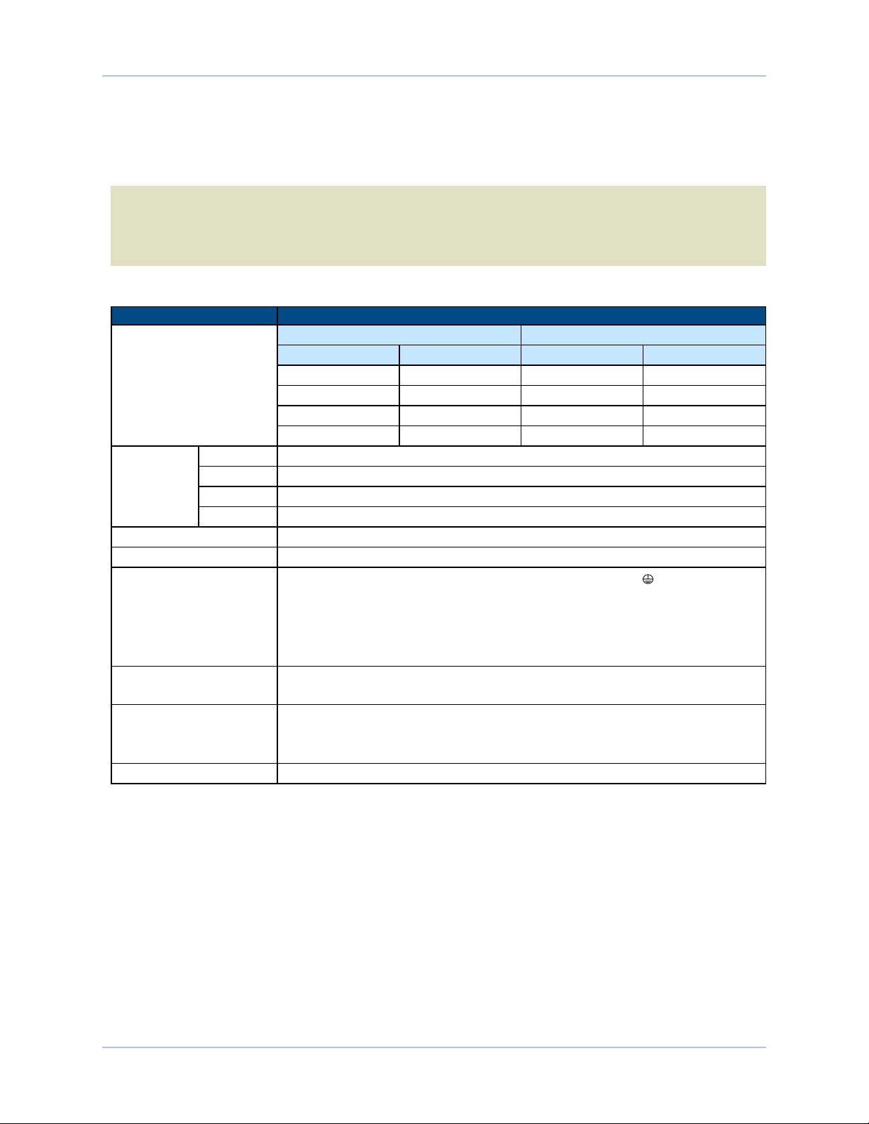
Table 1-2: Chassis Electrical Specifications
Description Specifications
Bus Voltage Options
4-Axis 8-Axis
Unipolar Bipolar Unipolar Bipolar
40 LP@ 300W 10B @ 400W 40LP @ 500W 10B @ 400W
80 LP @ 300W 20B @ 500W 40LP @ 500W 20B @ 500W
40 @ 600W 30B @ 500W 40LP @1000W 30B @ 500W
80 @ 600W 40B @ 600W 40LP @1000W 40B @ 1000W
Input
Current
100 VAC 10 A Maximum
115 VAC 10 A Maximum
200 VAC 6 A Maximum
230VAC 5 A Maximum
Inrush Current 100 A @ 254 VAC
Leakage Current <1/5 mA @ 60 Hz / 254 VAC
AC Power Input
AC input (factory configured): AC Hi, AC Lo, Earth Ground ( ),
l100 VAC (90-112 VAC, 49-63 Hz)
l115 VAC (103-127 VAC, 49-63 Hz)
l200 VAC (180-224 VAC, 49-63 Hz)
l230 VAC (207-254 VAC, 49-63 Hz)
Auxiliary Power Outputs +5 V is provided on all axis feedback connectors for encoder, Hall, and limit
power.
Protection
lPower switch breaker (10 Amps, Supplemental Protection only).
lFuses on motor bus supply transformer.
lBus supply inrush current limit during power-on.
Indicator (Power) Power switch contains a power-on indicator.
4 Chapter 1 www.aerotech.com
Introduction Npaq MR Hardware Manual
Aerotech doesn't specify the input current or power to the drives because it is dependent on the amount of
real power being delivered to the drive(refer to Section 1.1.1.).
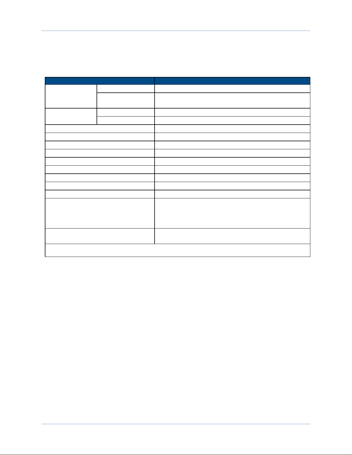
Table 1-3: Servo Amplifier Electrical Specifications (MP)
MP 10
Motor Supply
Input Voltage 10-80 VDC
Input Current
(Continuous) 5 Arms
Control Supply Input Voltage 24-80 VDC (±10%)
Input Current 1 Amax
Output Voltage (1) 10-80 VDC
Peak Output Current (1 second) 10 A
Continuous Output Current 5 A
Power Amplifier Bandwidth 2500 Hz maximum (software selectable)
Power Amplifier Efficiency 85% - 95%(2)
PWM Switching Frequency 20 kHz
Minimum Load Inductance 0.1 mH @ 80 VDC
User Power Supply Output 5 VDC (@ 500 milliamps)
Modes of Operation Brushless; Brush; Stepper
Protective Features
Output short circuit; Peak over current, DCbus over
voltages; RMSover current; Over temperature; Control
power supply under voltage; Power stage bias supply under
voltage
Isolation Optical and transformer isolation between control and power
stages.
1. AC input voltage and load dependent.
2. Dependent on total output power: efficiency increases with increasing output power.
www.aerotech.com Chapter 1 5

Npaq MR Hardware Manual Introduction
Table 1-4: Linear Amplifier Electrical Specifications (ML)
Description ML 10
Motor Supply
Input Voltage ±40 VDC (max)
Input Current
(continuous) 5 A
Input Current (peak) 10 A
Control Supply Input Voltage 24 VDC typical(18-36 VDC)
Input Current 700 mA (max)
Output Voltage (1) ±38V @ 10 A
Peak Output Current (2) 10
Continuous Output Current (2) 5
Power Amplifier Bandwidth 2500 Hz maximum (software selectable)
Minimum Load Resistance 0.5 Ω
Output Impedance 0.2 Ω (each phase)
User Power Supply Output 5 VDC (@ 500 mA)
Modes of Operation Brushless; Brush; Stepper
Protective Features Peak current limit; Over temperature; RMScurrent limit;
Dynamic power dissipation limit
Isolation Isolation between control and power stages.
1. Load Dependent
2. Peak and continuous output current is load dependent (the amplifier will limit its output current based on motor speed and motor
resistance).
6 Chapter 1 www.aerotech.com

Introduction Npaq MR Hardware Manual
1.1.1. System Power Requirements
The following equations can be used to determine total system power requirements. The actual power
required from the mains supply will be the combination of actual motor power (work), motor resistance
losses, and efficiency losses in the power electronics or power transformer.
For switching amplifier types:
An EfficiencyFactor of approximately 90% should be used in the following equations.
Brushless Motor
Output Power
Rotary Motors Pout [W] = Torque [N·m] * Angular velocity[rad/sec]
Linear Motors Pout [W] = Force [N] * Linear velocity[m/sec]
Rotary or Linear Motors Pout [W] = Bemf [V] * I(rms) * 3
Ploss = 3 * I(rms)^2 * R(line-line)/2
Pin = SUM (Pout + Ploss ) / EfficiencyFactor
DC Brush Motor
Pout [W] = Torque [N·m] * Angular velocity[rad/sec]
Ploss = I(rms)^2 * R
Pin = SUM (Pout + Ploss ) / EfficiencyFactor
For linear amplifier types:
An EfficiencyFactor of approximately 50% should be used in the following equations.
Linear Motor
Pdiss[W] = MotorCurrentPeak[A] * TotalBusVoltage[V] * 3 / 2
Pin = SUM (Pdiss ) / EfficiencyFactor
www.aerotech.com Chapter 1 7

Npaq MR Hardware Manual Introduction
1.2. Mechanical Specifications
The Npaq MR must be installed in a rack mount console to comply with safety standards. Mount the Npaq
MR so free airflow is available at the rear of the chassis. Allowance must also be made for the rear panel
connections and cables.
W A R N I N G : Use both handles to lift and carry the Npaq MR.
AEROTECH.COM
ON
OFF
Npaq MR
FEEDBACK
1
2 3 4
1 2 3 4
1 2 3 4
1 2 3 4
EXT DRIVE RS232
AUX ENCODER JOYSTICK
ESTOPMOTOR
DIGITAL / ANALOG IO
COMMUNICATIONS
424.9 [16.93]
333.7 [13.14]41.7 [1.64]
566.1 [22.29]
132.5 [5.22]
57.2 [2.25] 37.7 [1.48]
7.1 [0.28]
(4 pls)
482.6 [19.00]
8.3 [0.33] (TYP.) 465.9 [18.34]
444.5 [17.50]
Drawing Number: 620E1408-
Dimensions: MM [IN]
Figure 1-3: Dimensions (4 Axis Version)
8 Chapter 1 www.aerotech.com
Table of contents
Popular Enclosure manuals by other brands


TESTO
TESTO TopSafe 0516.0220 Application Information

Lian-Li
Lian-Li O11 DYNAMIC XL installation guide

Rockford Fosgate
Rockford Fosgate R1-1X10 Installation & operation

CRU Dataport
CRU Dataport Data Express DE275 install guide

Atlas
Atlas CS95-8 Specifications

Watts
Watts HIU2VSA-2 Installation and operating manual