Aerotech ACS100 User manual

Revision: 1.05.00
ACS Hardware Manual

Global Technical Support
Go to www.aerotech.com/global-technical-support for information and support about your Aerotech products. The website
supplies software, product manuals, Help files, training schedules, and PC-to-PC remote technical support. If necessary,
you can complete Product Return (RMA) forms and get information about repairs and spare or replacement parts. To get help
immediately, contact a service office or your sales representative. Include your customer order number in your email or have
it available before you call.
United States (World Headquarters)
Email: Support@aerotech.com
Phone: +1-412-967-6440
Fax: +1-412-967-6870
101 Zeta Drive
Pittsburgh, PA 15238-2811
www.aerotech.com
United Kingdom China
Email: Support@aerotech.com
Phone: +44 (0)1256 855055
Fax: +44 (0)1256 855649
Email: Support@aerotech.com
Phone: +86 (21) 5508 6731
Germany Taiwan
Email: Support@aerotech.com
Phone: +49 (0)911 967 9370
Fax: +49 (0)911 967 93720
Email: Support@aerotech.com
Phone: +886 (0)2 8751 6690
France
Email: Support@aerotech.com
Phone: +33 2 37 21 87 65
This manual contains proprietary information and may not be reproduced, disclosed, or used in whole or in part without the
express written permission of Aerotech, Inc. Product names mentioned herein are used for identification purposes only and
may be trademarks of their respective companies.
Copyright © 2006-2020, Aerotech, Inc., All rights reserved.

Table of Contents
ACS Hardware Manual 1
Table of Contents 3
List of Figures 4
List of Tables 5
Safety Procedures and Warnings 6
EU Declaration of Incorporation 7
Chapter 1: Overview 9
1.1. Environmental Specifications 12
1.2. Basic Specifications 13
1.3. Air Requirements 16
Chapter 2: Mechanical Specifications and Installation 17
2.1. Unpacking and Handling the Stage 17
2.2. Dimensions 18
2.3. Securing the Stage to the Mounting Surface 22
2.4. Clamping a Workpiece to the Collet 24
2.4.1. Load Capability 24
2.5. Changing the Workholding Devices 25
2.5.1. Collet Change Procedure 25
2.5.2. Changing Collet Chucks (ACS150) 27
2.5.3. Gripper Configurations (ACS150 and ACS200) 29
Chapter 3: Electrical Specifications and Installation 31
3.1. Motor and Feedback Connectors 32
3.2. Motor and Feedback Wiring 36
3.3. Motor and Feedback Specifications 39
3.4. Marker and Machine Direction 43
3.5. Motor and Feedback Phasing 44
Chapter 4: Maintenance 47
4.1. Stage Service and Inspection Schedule 47
4.2. Stage Cleaning and Lubrication 48
4.2.1. Collet and Collet Chuck Lubrication and Cleaning 49
4.3. Seal Replacement 50
4.3.1. Piston Seal Change Procedure 50
4.3.2. Rotary Union Seals for Three-Jaw Gripper Stages 54
4.4. Troubleshooting 56
Appendix A: Warranty and Field Service 57
Appendix B: Revision History 59
Index 61
www.aerotech.com 3
ACS Hardware Manual Table of Contents

List of Figures
Figure 1-1: ACSRotary Stage with Callouts 11
Figure 2-1: ACS100 Dimensions 18
Figure 2-2: ACS150 (-ER Chuck Style) Dimensions 19
Figure 2-3: ACS150 (-3J Chuck Style) Dimensions 20
Figure 2-4: ACS200 (-3J Chuck Style) Dimensions 21
Figure 2-5: ACS Stage Mounting Holes 23
Figure 2-6: Typical ACS150 Stage Showing Side Mounting Holes and T-Slot Detail 23
Figure 2-7: Schematic of Collet Insertion Into and Removal From Collet Nut 26
Figure 2-8: Installation Procedure for Collet 26
Figure 2-9: Collet Assembly Exploded View 27
Figure 2-10: Gripper Mounting Hole Locations in ACS Shaft 29
Figure 2-11: Mounting Holes for Three-Jaw Gripper 30
Figure 2-12: Air Inlets in Three-Jaw Grippers 30
Figure 3-1: Motor and Feedback Wiring (ACS100 -CN1) 36
Figure 3-2: Motor and Feedback Wiring (ACS100 -CN2) 37
Figure 3-3: Motor and Feedback Wiring (ACS150 and ACS200) 38
Figure 3-4: Machine Direction 43
Figure 3-5: Hall Phasing 44
Figure 3-6: Analog Encoder Phasing Reference Diagram 45
Figure 3-7: Encoder Phasing Reference Diagram (Standard) 45
Figure 4-1: Piston Seal Change Exploded View 50
Figure 4-2: Piston Seal Installation Procedure 53
Figure 4-3: Cross-Section View of Piston Showing Seal Orientation 53
Figure 4-4: Exploded Drawing of Rear Seal Components 54
Figure 4-5: Cross-section View of Rear Seal Showing Seal Orientations 55
List of Figures ACS Hardware Manual
4 www.aerotech.com

List of Tables
Table 1-1: ACS100 Model Numbering System 9
Table 1-2: ACS150 Model Numbering System 10
Table 1-3: ACS200 Model Numbering System 11
Table 1-4: Environmental Specifications 12
Table 1-5: ACS100 Series Specifications 13
Table 1-6: ACS150 Series Specifications 14
Table 1-7: ACS200 Series Specifications 15
Table 2-1: Stage to Mounting Surface Hardware 22
Table 3-1: Motor Pinouts (-CN1option on the ACS100; standard on the ACS150 and ACS200) 33
Table 3-2: Mating Connector Part Numbers for the Motor Connector (-CN1option on the ACS100;
standard on the ACS150 and ACS200) 33
Table 3-3: Motor Pinouts (-CN2 option on the ACS100 only) 34
Table 3-4: Mating Connector Part Numbers for the -CN2 Motor Option Connector 34
Table 3-5: Feedback Pinouts 35
Table 3-6: Mating Connector Part Numbers for the Feedback Connector 35
Table 3-7: Feedback Specifications 39
Table 3-8: Encoder Specifications 39
Table 3-9: Maximum Speed (rpm) Per Encoder Option 39
Table 3-10: Motor Specifications (ACS100) 40
Table 3-11: Motor Specifications (ACS150) 41
Table 3-12: Motor Specifications (ACS200) 42
Table 4-1: Recommended Lubricants 49
Table 4-2: Piston Seal Replacement Part Numbers 50
Table 4-3: Rotary Union Seal Replacement Part Numbers 54
www.aerotech.com 5
ACS Hardware Manual List of Tables

Safety Procedures and Warnings
This manual tells you how to carefully and correctly use and operate the ACS. Read all parts of this manual
before you install or operate the ACS or before you do maintenance to your system. To prevent injury to you
and damage to the equipment, obey the precautions in this manual. The precautions that follow apply when
you see a Danger or Warning symbol in this manual. If you do not obey these precautions, injury to you or
damage to the equipment can occur. If you do not understand the information in this manual, contact
Aerotech Global Technical Support.
This product has been designed for light industrial manufacturing or laboratory environments. The protection
provided by the equipment could be impaired if the product is used in a manner not specified by the
manufacturer.
D A N G E R : This product contains potentially lethal voltages. To reduce the possibility of
electrical shock, bodily injury, or death the following precautions must be followed.
1. Access to the ACS and component parts must be restricted while connected to a power
source.
2. Do not connect or disconnect any electrical components or connecting cables while
connected to a power source.
3. Disconnect electrical power before servicing equipment.
4. All components must be properly grounded in accordance with local electrical safety
requirements.
5. Operator safeguarding requirements must be addressed during final integration of the
product.
W A R N I N G : To minimize the possibility of electrical shock, bodily injury or death the
following precautions must be followed.
1. Moving parts can cause crushing or shearing injuries. Access to all stage and motor parts
must be restricted while connected to a power source.
2. Cables can pose a tripping hazard. Securely mount and position all system cables to avoid
potential hazards.
3. Do not expose this product to environments or conditions outside of the listed
specifications. Exceeding environmental or operating specifications can cause damage to
the equipment.
4. The ACS stage must be mounted securely. Improper mounting can result in injury and
damage to the equipment.
5. Use care when moving the ACS stage. Lifting or transporting the ACS stage improperly
can result in injury or damage to the ACS.
6. This product is intended for light industrial manufacturing or laboratory use. Use of this
product for unintended applications can result in injury and damage to the equipment.
7. If the product is used in a manner not specified by the manufacturer, the protection
provided by the product can be impaired and result in damage, shock, injury, or death.
8. Operators must be trained before operating this equipment.
9. All service and maintenance must be performed by qualified personnel.
Safety Procedures and Warnings ACS Hardware Manual
6 www.aerotech.com

EU Declaration of Incorporation
Manufacturer:
Aerotech, Inc.
101 Zeta Drive
Pittsburgh, PA 15238-2811
USA
herewith declares that the product:
ACS Stage
is intended to be incorporated into machinery to constitute machinery covered by the Directive 2006/42/EC
as amended;
and that the following harmonized European standards have been applied:
EN ISO 12100:2010
Safety of machinery - Basic concepts, general principles for design
EN 60204-1:2010
Safety of machinery - Electrical equipment of machines - Part 1:General requirements
and further more declares that
it is not allowed to put the equipment into service until the machinery into which it is to
be incorporated or of which it is to be a component has been found and declared to be in
conformity with the provisions of the Directive 2006/42/EC and with national
implementing legislation, for example, as a whole, including the equipment referred to in
this Declaration.
This is to certify that the aforementioned product is in accordance with the applicable requirements of the fol-
lowing Directive(s):
EU 2015/863 RoHS3 Directive
Authorized Representative:
Simon Smith, European Director
Address:
Aerotech Ltd
The Old Brick Kiln, Ramsdell, Tadley
Hampshire RG26 5PR
UK
Name
/ Alex Weibel
Position
Engineer Verifying Compliance
Location
Pittsburgh, PA
Date
3/31/2020
www.aerotech.com 7
ACS Hardware Manual EU Declaration of Incorporation

This page intentionally left blank.
EU Declaration of Incorporation ACS Hardware Manual
8 www.aerotech.com

Chapter 1: Overview
N O T E : Aerotech continually improves its product offerings; listed options may be superseded at any
time. All drawings and illustrations are for reference only and were complete and accurate as of this
manual’s release. Refer to www.aerotech.com for the most up-to-date information.
Table 1-1: ACS100 Model Numbering System
ACS Mechanical-Bearing Direct-Drive Rotary Collet Stage, 100 mm diameter
Stage Size (Required)
-85 85 mm stage height; 0.6 N·m continuous torque
-135 135 mm stage height; 1.6 N·m continuous torque
Chuck Style (Required)
-ER8 ER8 ultra-precision collet
-ER8MB ER8 microbore collet
Feedback (Required)
-E1 Incremental encoder, 1 Vpp, sine wave output
-E2 Incremental encoder, Digital, RS422 line-driver, x5 interpolation
-E3 Incremental encoder, Digital, RS422 line-driver, x10 interpolation
-E4 Incremental encoder, Digital, RS422 line-driver, x25 interpolation
-E5 Incremental encoder, Digital, RS422 line-driver, x50 interpolation
NOTE: Digital output encoder signals are synthesized with a 16 MHz clock. Ensure that the encoder sample rate on the controller is
at least 16 MHz or higher (slower clock rates are available on request).
Rear Seal (Optional)
-SL Rear seal
Connector (Required)
-CN1 4-pin high-powered D-style motor and 25-pin D-style feedback connectors
-CN2 25-pin D-style motor and 25-pin D-style feedback connectors
Wrench (Optional)
-WR Wrench for changing the collet
Aerotech P/N:MFB25378-01 [Qty-2]
Air Purge (Optional)
-PR Air purge fitting to positive pressurize ACS stage to limit ingress of airborne
particulates
Metrology (Required)
-PL1 Uncalibrated with performance plots
-PL2 Calibrated (HALAR) with performance plots
Accessories (To be Ordered as a Separate Line Item)
Collet-ER8-CLTxx ER8 DIN6499AA electropolished collet, 0.5 mm to 5 mm part sizes diameter
available
Collet-ER8MB-CLTxx ER8 DIN6499AA electropolished mircro-bore collet, 0.2 mm to 0.9 mm part sizes
diameter available
CGF Collet and gripper filtration kit
www.aerotech.com 9
ACS Hardware Manual Chapter 1: Overview

Table 1-2: ACS150 Model Numbering System
ACS Mechanical-Bearing Direct-Drive Rotary Collet Stage, 150 mm diameter
Stage Size (Required)
-115 115 mm stage height; 2.9 N·m continuous torque
-135 135 mm stage height; 5.1 N·m continuous torque
-180 185 mm stage height; 9.3 N·m continuous torque
Chuck Style (Required)
-ER25 ER25 ultra-precision collet
-ER40 ER40 ultra-precision collet
-3J1 3-Jaw gripper, 10 mm stroke, normally closed
-3J2 3-Jaw gripper, 10 mm stroke, normally open
-3J3 3-Jaw gripper, 16 mm stroke, normally closed
-3J4 3-Jaw gripper, 16 mm stroke, normally open
Feedback (Required)
-E1 Incremental encoder, 1 Vpp, sine wave output
-E2 Incremental encoder, Digital, RS422 line-driver, x5 interpolation
-E3 Incremental encoder, Digital, RS422 line-driver, x10 interpolation
-E4 Incremental encoder, Digital, RS422 line-driver, x25 interpolation
-E5 Incremental encoder, Digital, RS422 line-driver, x50 interpolation
NOTE: Digital output encoder signals are synthesized with a 16 MHz clock. Ensure that the encoder sample rate on the controller is
at least 16 MHz or higher (slower clock rates are available on request).
Rear Seal (Optional)
-SL Rear seal
Wrench (Optional)
-WR
Wrench for changing the collet
Aerotech P/N:MCA01857 [Qty-1]
Aerotech P/N:MCA02007 [Qty-1]
Metrology (Required)
-PL1 Uncalibrated with performance plots
-PL2 Calibrated (HALAR) with performance plots
Accessories (To be Ordered as a Separate Line Item)
Collet-ER25-CLTxx ER25 DIN6499AA electropolished collet, 0.5 mm to 15 mm part holding sizes
available
Collet-ER40-CLTxx ER40 DIN6499AA electropolished collet, 15.5 mm to 25 mm part holding sizes
available
CGF Collet and gripper filtration kit
NOTE: ER40 collet sizes less than 15.5 mm diameter are not supported. Use the ER25 collect chuck if these sizes are required.
Chapter 1: Overview ACS Hardware Manual
10 www.aerotech.com

Table 1-3: ACS200 Model Numbering System
ACS Mechanical-Bearing Direct-Drive Rotary Collet Stage, 200 mm diameter
Stage Size (Required)
-155 155 mm stage height; 11.1 N·m continuous torque
-185 185 mm stage height; 15.9 N·m continuous torque
Chuck Style (Required)
-3J1 3-Jaw gripper with 12 mm clear aperture, 10 mm stroke, normally closed
-3J2 3-Jaw gripper with 12 mm clear aperture, 10 mm stroke, normally open
-3J3 3-Jaw gripper with 12 mm clear aperture, 16 mm stroke, normally closed
-3J4 3-Jaw gripper with 12 mm clear aperture, 16 mm stroke, normally open
-3J5 3-Jaw gripper with 25 mm clear aperture, 13 mm stroke, normally closed
-3J6 3-Jaw gripper with 25 mm clear aperture, 13 mm stroke, normally open
-3J7 3-Jaw gripper with 25 mm clear aperture, 20 mm stroke, normally closed
-3J8 3-Jaw gripper with 25 mm clear aperture, 20 mm stroke, normally open
Feedback (Required)
-E1 Incremental encoder, 1 Vpp, sine wave output
-E2 Incremental encoder, Digital, RS422 line-driver, x5 interpolation
-E3 Incremental encoder, Digital, RS422 line-driver, x10 interpolation
-E4 Incremental encoder, Digital, RS422 line-driver, x25 interpolation
-E5 Incremental encoder, Digital, RS422 line-driver, x50 interpolation
NOTE: Digital output encoder signals are synthesized with a 16 MHz clock. Ensure that the encoder sample rate on the controller is
at least 16 MHz or higher (slower clock rates are available on request).
Metrology (Required)
-PL1 Uncalibrated with performance plots
-PL2 Calibrated (HALAR) with performance plots
Accessories (To be Ordered as a Separate Line Item)
CGF Collet and gripper filtration kit
Figure 1-1: ACSRotary Stage with Callouts
www.aerotech.com 11
ACS Hardware Manual Chapter 1: Overview

1.1. Environmental Specifications
W A R N I N G : Do not expose this product to environments or conditions outside of the listed
specifications. Exceeding environmental or operating specifications can cause damage to the
equipment.
Table 1-4: Environmental Specifications
Ambient
Temperature
Operating: 10° to 35° C (50° to 95° F)
The optimal operating temperature is 20° C ±2° C (68° F ±4° F). If at any time the
operating temperature deviates from 20° C, degradation in performance could occur.
Storage: 0° to 40° C (32° to 104° F) in original shipping packaging
Humidity
Operating: 20% to 60% RH
Storage: 10% to 70% RH, non-condensing in original packaging. The stage should be
packaged with desiccant if it is to be stored for an extended time.
Altitude
Operating: 0 m to 2,000 m (0 ft to 6,562 ft) above sea level
Contact Aerotech if your specific application involves use above 2,000 m or below sea
level.
Vibration
Use the system in a low vibration environment. Excessive floor or acoustical vibration
can affect system performance. Contact Aerotech for information regarding your spe-
cific application.
Protection
Rating
The ACS stages are not suited for dusty or wet environments. This equates to an
ingress protection rating of IP40.
Use Indoor use only
1.1. Environmental Specifications ACS Hardware Manual
12 www.aerotech.com

1.2. Basic Specifications
N O T E : Aerotech continually improves its product offerings; listed options may be superseded at any
time. All drawings and illustrations are for reference only and were complete and accurate as of this
manual’s release. Refer to www.aerotech.com for the most up-to-date information.
Table 1-5: ACS100 Series Specifications
ACS Series ACS100-85 ACS100-135
Total Travel ±360° Continuous
Collet Option(1)(6) ER8
Maximum Torque (Continuous) 0.48 N·m 1.6 N·m
Accuracy(2) Calibrated ±73 µrad (±15 arc sec)
Uncalibrated ±146 µrad (±30 arc sec)
Repeatability(2) ±29 µrad (±6 arc sec)
Pin/Collet Runout (ERCollets)(3) <25 µm
Grip Repeatability / Max Jaw Length (3 Jaw) ± 20 µm / 50 mm
Maximum Aperture ER8 5 mm 5 mm
Maximum Load(4) ER8 1.5 kg (Axial); 0.5 kg (Radial); 0.75 N·m
(Moment)
Rated Speed(5) 800 rpm
Bus Voltage Up to 340 VDC
Total Mass 2.5 kg 4.5 kg
Finish Table Hardcoat
Stage Black Anodize
1. ACS collet chuck accepts Rego-Fix ER collets manufactured to DIN6499 specifications only.
2. Repeatability and accuracy are dependent on encoder resolution. To achieve the listed specifications, encoder resolution must
be 1.2 arc sec or less.
3. Measured TIR of precision gage pin chucked with an ultra precision ER collet (DIN6499) 6 mm away from collet face with no load.
4. Maximum loads are mutually exclusive. Loading limits are due to the collet chuck mechanism. Contact Aerotech directly if part
load requirement exceeds specifications.
5. Maximum speed based on stage capability. Maximum application velocity may be limited by system data rate and system
resolution.
6. Collet chuck mechanism is normally-closed. Collet mechanism requires air to open collet chuck. Air supply must be dry (0ºF dew-
point) oil-less air OR 99.99% pure Nitrogen. Air or nitrogen must be filtered to 1 micron particle size or better.
www.aerotech.com 13
ACS Hardware Manual 1.2. Basic Specifications
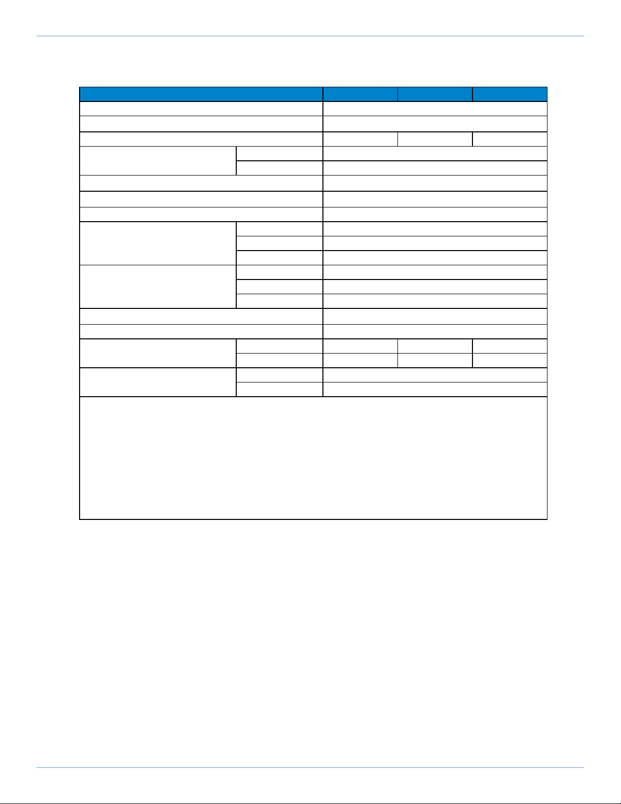
Table 1-6: ACS150 Series Specifications
ACS Series ACS150-115 ACS150-135 ACS150-180
Total Travel ±360° Continuous
Gripper/Collet Option(1)(6) ER25, ER40, 3J-12
Maximum Torque (Continuous) 2.85 N·m 5.06 N·m 9.29 N·m
Accuracy(2) Calibrated ±73 µrad (±15 arc sec)
Uncalibrated ±146 µrad (±30 arc sec)
Repeatability(2) ±29 µrad (±6 arc sec)
Pin/Collet Runout (ERCollets)(3) <25 µm
Grip Repeatability/Max Jaw Length (3 Jaw) ±20 µm/50 mm
Maximum Aperture
ER25 16 mm
ER40 30 mm
3J-12 12 mm
Maximum Loads(4)
ER25 10 kg (Axial); 5 kg (Radial); 6 N·m (Moment)
ER40 15 kg (Axial); 10 kg (Radial); 12 N·m (Moment)
3J-12 20 kg (Axial); 11 kg (Radial); 6 N·m (Moment)
Rated Speed(5) 600 rpm
Bus Voltage Up to 340 VDC
Total Mass ER25 / ER40 8.0 kg 10.0 kg 14.0 kg
3J-12 7.8 kg 9.7 kg 13.7 kg
Finish Table Hardcoat
Stage Black Anodize
1. ACS collet chuck accepts Rego-Fix ER collets manufactured to DIN6499 specifications only.
2. Repeatability and accuracy are dependent on encoder resolution. To achieve the listed specifications, encoder resolution must
be 1.2 arc sec or less.
3. Measured TIR of precision gage pin chucked with an ultra precision ER collet (DIN6499) 6 mm away from collet face with no load.
4. Maximum loads are mutually exclusive. Loading limits are due to the collet chuck mechanism. Contact Aerotech directly if part
load requirement exceeds specifications.
5. Maximum speed based on stage capability. Maximum application velocity may be limited by system data rate and system
resolution.
6. Collet chuck mechanism is normally-closed. Collet mechanism requires air to open collet chuck. Air supply must be dry (0ºF dew-
point) oil-less air OR 99.99% pure Nitrogen. Air or nitrogen must be filtered to 1 micron particle size or better. With 3-jaw gripper, air
or nitrogen should be filtered to 20 micron particle size or better.
1.2. Basic Specifications ACS Hardware Manual
14 www.aerotech.com

Table 1-7: ACS200 Series Specifications
ACS Series ACS200-155 ACS200-185
Total Travel ±360° Continuous
Gripper Option 3J1 through 3J8
Maximum Torque (Continuous) 11.2 N·m 15.93 N·m
Accuracy(1) Calibrated ±73 µrad (±15 arc sec)
Uncalibrated ±146 µrad (±30 arc sec)
Repeatability(1) ±29 µrad (±6 arc sec)
Grip Repeatability(2) ±20 µm
Max Jaw Length from Chuck
Face
3J-12 50 mm
3J-25 70 mm
Aperture 3J-12 12 mm
3J-25 25 mm
Maximum Loads(3) 3J-12 20 kg (Axial); 11 kg (Radial); 6 N·m
(Moment)
3J-25 30 kg (Axial); 18 kg (Radial); 13 N·m
(Moment)
Rated Speed(4) 600 rpm
Bus Voltage 340 VDC
Total Mass 20.2 kg 24.3 kg
Finish Table Hardcoat
Stage Black Anodize
1. Repeatability and accuracy are dependent on encoder resolution. To achieve the listed specifications, encoder resolution must
be 1.2 arc sec or less.
2. Measured TIR of precision gage pin 10 mm away from gripper face with no load.
3. Maximum loads are mutually exclusive. Loading limits are due to the collet chuck mechanism. Contact Aerotech directly if part
load requirement exceeds specifications.
4. Maximum speed based on stage capability. Maximum application velocity may be limited by system data rate and system
resolution.
www.aerotech.com 15
ACS Hardware Manual 1.2. Basic Specifications

1.3. Air Requirements
The air pressure supplied to the collet holder or gripper is important in ensuring that the material or tool is
released properly, or for the optional gripper, that the material is held securely.
lIf compressed air is used, it must be filtered to 1 micron, dry to 0º F dew point, and oil free.
lIf nitrogen is used, it must be 99.99% pure and filtered to 1 microns.
For stages equipped with a three-jaw gripper, air must be regulated to between 3 and 7 bar (45 and 100 psig).
Higher pressures could cause damage to the gripper assembly and should be avoided. The chuck becomes
fully open at approximately 4-7 bar (60-100 psig) depending on the collet size. Higher pressures will not
cause damage to the rotary union, but high flow rates will result. Because of the noncontact rotary union
design on collet-equipped stages, a small amount of leakage will occur. Approximate leakage rates of
between 10 Lpm (0.5 CFM) and 40 Lpm (1.4 CFM), depending on pressure, will be observed when the collet
is open.
1.3. Air Requirements ACS Hardware Manual
16 www.aerotech.com

Chapter 2: Mechanical Specifications and Installation
W A R N I N G : ACS installation must be in accordance to instructions provided by this manual
and any accompanying documentation. Failure to follow these instructions could result in injury
or damage to the equipment.
2.1. Unpacking and Handling the Stage
W A R N I N G : It is the customer's responsibility to safely and carefully lift the stage.
lMake sure that all moving parts are secure before moving the ACS. Unsecured moving
parts may shift and cause bodily injury.
lImproper handling could adversely affect the performance of the ACS. Use care when
moving the ACS.
lLift only by the base. Do not use the tabletop or cables as lifting points.
N O T E : If any damage has occurred during shipping, report it immediately.
Carefully remove the ACS stagefrom its protective shipping container. Gently set the ACS stage on a
smooth, flat, and clean surface.
Before operating the ACS stage, it is important to let it stabilize at room temperature for at least 12 hours.
Allowing it to stabilize to room temperature will ensure that all of the alignments, preloads, and tolerances are
the same as they were when tested at Aerotech. Use compressed nitrogen or clean, dry, oil-free air to
remove any dust or debris that has collected during shipping.
Each ACS has a label listing the system part number and serial number. These numbers contain information
necessary for maintaining or updating system hardware and software. Locate this label and record the
information for later reference.
Shipping Clamps
If the ACS has shipped as part of a system, shipping clamps (typically red, anodized aluminum) may have
been installed to secure the system prior to shipment. The shipping clamps, if installed, will need to be
removed prior to machine start up.
www.aerotech.com 17
ACS Hardware Manual Chapter 2: Mechanical Specifications and Installation

2.2. Dimensions
N O T E : Aerotech continually improves its product offerings; listed options may be superseded at any
time. All drawings and illustrations are for reference only and were complete and accurate as of this
manual’s release. Refer to www.aerotech.com for the most up-to-date information.
Figure 2-1: ACS100 Dimensions
2.2. Dimensions ACS Hardware Manual
18 www.aerotech.com

Figure 2-2: ACS150 (-ER Chuck Style) Dimensions
www.aerotech.com 19
ACS Hardware Manual 2.2. Dimensions

Figure 2-3: ACS150 (-3J Chuck Style) Dimensions
2.2. Dimensions ACS Hardware Manual
20 www.aerotech.com
This manual suits for next models
9
Table of contents
Popular Power Tools manuals by other brands

Parkside
Parkside PBSG 95 E6 Translation of the original instructions

SM CONTACT
SM CONTACT SM CRIMP 2000 Operator's manual

Bosch
Bosch GSC 160 Professional Original instructions

Bosch
Bosch GST Professional 65 Original instructions

Rockwell
Rockwell Shop Series instruction manual

Kyocera
Kyocera TJEP FH 21/90 GAS 2G manual

Bartell
Bartell BR3570 Owner's manual and parts book

Stanley
Stanley FATMAX V20 SFMCN618 manual

BorMann
BorMann PRO BDC3200 user manual

RAMSET
RAMSET LOW VELOCITY POWDER ACTUATED TOOL Operator's instruction & training manual

Bosch
Bosch GDR 14 Original instructions

Cembre
Cembre RH50 Operation and maintenance manual


