Aerovent IM-895 Instruction manual

Centrifugal Fans
Installation, Operation & Maintenance Manual
Gas
Door Air Heaters
IM-895
July 2021
This manual has been prepared to guide the users of gas door air heater units in the proper installation, operation and maintenance
procedures to ensure maximum equipment life with trouble-free operation. For safe installation, startup and operational life of
this equipment, it is important that all involved with the equipment be well-versed in proper door air heater safety practices and
read this manual. It is the user’s responsibility to make sure that all requirements of good safety practices and any applicable
safety codes are strictly adhered to. Additional product and engineering information is available at www.aerovent.com.
Refer to the Safety section(s) in this manual prior to installing or servicing the door air heater. The most current version of this installation
and maintenance manual can be found on our website at www.aerovent.com/resources/im-manuals.
SAFETY NOTICE
REVIEW AMCA BULLETIN 410 PRIOR TO INSTALLATION
Table of Contents
Safety & Hazard Warnings ......................................................... 2
Receiving, Inspection & Unpacking...........................................3
Unit Storage ................................................................................3
Handling ......................................................................................3
General Installation.....................................................................4
Unit Installation (Gas Connections)........................................... 5
Unit Installation (Electrical Connections)..................................6
Control Cabinet Features.........................................................7-8
Unit Features...............................................................................8
Accessories..................................................................................9
Check, Test & Start Procedure............................................. 10-12
Commissioning...........................................................................12
Sequence of Operation .............................................................13
Final Step....................................................................................13
Maintenance ......................................................................... 14-15
Troubleshooting Guidelines .................................................15-16
Start-up Checklist and Report...................................................17
Field Start-Up Sheet..............................................................18-22
Model ADH

Installation, Operation & Maintenance Manual
IM-895
2
Safety & Hazard Warnings
For general safety practices for air moving equipment, see AMCA Bulletin 410. Aerovent offers many safety accessories. These
safety devices include (but are not limited to) Firestat, inlet and discharge screens. The use and suitability of safety devices is the
responsibility of the purchaser.
The use and storage of gasoline or other flammable vapors and liquids in open containers in the vicinity of this appliance is
hazardous. If you smell gas:
• Open windows (indoor installation only)
• Do not touch electrical switches
• Extinguish any open flame
• Immediately call your gas supplier
Facility-related safety conditions include fans’ accessibility and location. How easily can non-service personnel access the unit? Is
the fan in a hazardous duty environment? Was the unit ordered for this duty? Other concerns must also be addressed. All fans
should be powered through switches, which are easily accessible to service personnel from the fan. Fan power must have the
ability to be “locked out” by service personnel trained in lockout/tagout procedures per OSHA requirements (29CFR1910.147).
When performing lockout, be aware of factors, such as building pressure and additional fans in the system that can influence
unwanted fan rotation (wind milling). If you have any doubt about your ability to perform a task, seek a person qualified to do that
task. Before any work is done on a fan, ensure that the fan is isolated from the electrical supply using a 'lockout/tagout system.'
Note: A stationary, non-rotating fan does not mean that the fan is isolated from the electrical supply. A non-rotating fan could be
subject to controls or other circuit protection devices that may start the fan without notice.
The following safety precautions should be followed, where applicable:
• Do not attempt to slow a rotating impeller even when it is isolated from the electrical supply. Fan impellers have a high inertia
and injury could result from an attempt to stop it. It is recommended that the impeller is isolated by closing off the inlet or
outlet to prevent wind-driven rotation. If an impeller is chocked to prevent rotation, ensure that the chocks are removed prior
to start up.
• Wear appropriate personal protective equipment. This may include protective clothing, eye protection, ear protection,
respiratory equipment, hand and foot protection when installing or servicing the fan.
• Always use caution when entering a fan's air path. High velocity airflow can cause you to lose your balance.
• Motor, bearings and drives can be hot, and similarly if the fan is subject to processes that are hot, the fan housing could be
hot.
• Fans are often used to move hazardous materials that could be dangerous. Always wear protective clothing and take
precautions not to inhale dust/gases. If hazardous chemical vapors are present, respiratory equipment may be required.
• Sharp edges – wear protective gloves when handling, installing or servicing a fan.
• Fans can operate at high decibel sound levels. Wear proper ear protection to protect from excessive noise levels.
• Access Doors – Do not open access doors when fan is in operation. The effects of suction and air pressure could result in injury.
• When working around pulleys and belts, keep hands away from pinch points. This pertains to when the fan is under or off
power.
Throughout this manual, there are a number of HAZARD WARNINGS that must be read and adhered to in order to prevent
possible personal injury and/or damage to equipment. Two signal words "WARNING" and "CAUTION" are used to indicate the
severity of a hazard and are preceded by the safety alert symbol. It is the responsibility of all personnel involved in installation,
operation and maintenance to fully understand the warning and caution procedures by which hazards are to be avoided.
DANGER: Indicates the most serious hazard and is used when serious injury or death WILL result from misuse or failure to
follow specific instructions.
WARNING: Used when serious injury or death MAY result from misuse or failure to follow specific instructions.
CAUTION: Used when minor or moderate injury or product / equipment damage MAY result from misuse or failure to follow
specific instructions.
NOTICE: Indicates information considered important, but not hazard-related.

Installation, Operation & Maintenance Manual IM-895
3
Unit Storage
If door air heater installation is to be delayed, store the unit in an environmentally stable and protected area. The unit should be
reasonably protected from any accidental impacts. Cover the door air heater to prevent any foreign material or moisture from
entering the inlet or discharge.
Receiving, Inspection & Unpacking
When the equipment is received all items should be carefully checked against the bill of lading to be sure all crates and cartons
have been received. Before accepting delivery, carefully inspect each carton or crate for visible shipping damage. If any damage
is noticed, the carrier should make the proper notation on the delivery receipt acknowledging the damage. Make notations of all
damage on all copies of the bill of lading and have all copies countersigned by the delivering carrier. The carrier should also fill
out a Carrier Inspection Report. The factory Traffic Department should then be contacted. File claim for damage with the carrier.
Physical damage to the unit after acceptance is not the responsibility of Twin City Fan Companies, Ltd.
Unpack each carton or crate and verify for conformance with description of product ordered and all required parts and proper
quantities of each item have been received. Refer to drawings for part descriptions. Report shortages or missing items to your
local representative to arrange for replacement parts. Due to availability of carriers and truck space, it is not possible to guarantee
that all items will be shipped together. Verification of shipments must be limited to only those items on the bill of lading.
The unit nameplate must be checked to make sure the voltage agrees with the power supply available.
Handling
Handling of all air moving equipment should be conducted
by trained personnel and be consistent with safe handling
practices. Verify the lift capacity and operating condition
of handling equipment. When using hoisting equipment,
only qualified and trained personnel should operate the
equipment.
1. Maintain handling equipment to avoid serious personal injury and
do not stand under the load.
2. If supplied, only use the provided lifting lugs to lift the equipment.
3. Ensure that the lifting equipment is rated for the capacity to be
lifted.
CAUTION
Installation, Operation & Maintenance Manual
IM-895
4
Sheet metal parts, screws, clips and similar items inherently
have sharp edges and it is necessary that the installer and
service personnel exercise caution.
CAUTION
General Installation
The installation of this equipment shall be in accordance with the regulations of authorities having jurisdiction and all applicable
codes.
This equipment is to be installed by an experienced installation company and fully trained personnel.
The mechanical and electrical installation of the door air heater consists of making final connections between the unit and
building services.
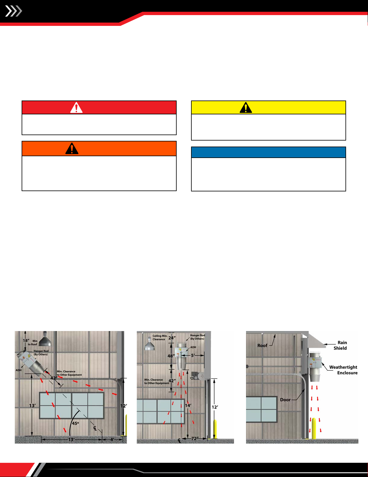
Prior to installing the unit in the final location, review the following:
1. Follow site preparation instructions for suspended mounting recommendations.
2. Check the rating plate of the unit before lifting to ensure that the model number shown matches that shown on the plans.
Although the units may look similar, their function, capacities, options and accessories may vary widely.
3. Check the unit dimensions for proper fit.
4. Hanger rods and channel iron, adequate to support the weight of the unit, will be required.
5. Attach the hanger rods to the building structure so they hang down and attach to the angle rings on the door air heater. Make
sure the rod locations do not interfere with gas train or electrical control panel access. If desired, provide one suspension
type vibration isolator in each hanger rod. The minimum combined ratings of the vibration isolators and suspension materials
should equal 150% of the total weight of the fully assembled unit.
6. Move the unit to its installation location.
7. Fully assemble the unit with all included components.
8. Raise the unit so that the hanger rods drop through the hole(s) in the angle extension.
9. Attach two nuts to each hanger rod and jamb the two nuts together to prevent loosening.
Failure to follow proper lifting instructions could result in
property damage, serious injury or death. Lifting should only
be done by a qualified rigging company. Use ALL lifting points.
Test lift to ensure proper balance and rigging. Never lift in high
winds.
WARNING NOTICE
Installation in an airplane hangar must be in accordance with
the Standard for Aircraft Hangars, ANSI/ NFPA 409 and (2)
public garage in accordance with the Standard from Parking
Structures, ANSI/NFPA 88A or the Standard for Repair Garages,
ANSI/NFPA 88B and with CAN/CGA B149 Installation Codes.
Appliances must not be installed where they may be exposed
to a potentially explosive or flammable atmosphere.
DANGER
Interior – 45° Angle Interior – Vertical Exterior – Vertical

Installation, Operation & Maintenance Manual IM-895
5
Follow proper handling instructions as given earlier.
1. Installation of piping must be in accordance with local
codes and ANSI Z223.1-latest edition, "National Fuel Gas
Codes" (in Canada CAN/CGA-B149 Code).
2. Piping to the unit must conform to local and national
requirements for type and volume of gas handled, and
pressure drop allowed in the line. Refer to the unit rating
plate to determine the BTU capacity of the unit and
the type of gas the unit is designed to use. Using this
information, refer to the ASHRAE Guide Fundamentals
Handbook, or other gas pipe sizing guides, to determine
the correct supply pipe size. Allow sufficient pipe size
based on allowable pressure drop in supply line. Where
several units are served by the same main, the total
capacity of all the units served by the main must be used.
Do not use pipe sizes smaller than 1/2".
3. Pipe size to the unit must match the factory side access
gas connection size, 1" NPT.
4. Install a ground joint union with brass seat and a manual
shut-off valve external to the unit casing, as shown in
Figure 7.1, adjacent to the unit for emergency shut-off
and easy servicing of controls. Include a 1/8" NPT plugged
tapping accessible for test gauge connections.
5. Provide a sediment trap, as shown in Figure 7.1, before
each unit and where low spots in the pipeline cannot be
avoided.
6. This unit requires a constant minimum gas supply pressure,
6.5" w.c., when the unit is operating at maximum gas flow.
If the gas supply pressure exceeds 1 psig, a gas pressure
regulator must be installed before the unit to prevent
damage to the internal valve components. If the pressure
is lower than 6.5" w.c., the heater may not perform to
specifications.
7. Support piping so that no strains are imposed on the unit
controls when connected.
Unit Installation (Gas Connections)
1. All field gas supply lines should be pressure/leak tested prior to operation. Never use an open flame. Use a soap solution or equivalent
for testing.
2. Gas pressure to the unit controls must never exceed the pressure shown on the unit rating plate. The unit and its individual shutoff valve(s)
must be disconnected from the gas supply during any test pressure more than 0.5 psig (3.5 kPa).
3. For test pressure less than 0.5 psig (3.5 kPa), the unit gas control must be isolated from the supply gas piping by closing the unit manual
shutoff valve(s).
4. For an indoor unit, where required by Code, use a dedicated line for venting gas to the outside of the building.
WARNING
1. Purging of air from gas supply lines should be performed
as described in ANSI Z223.1-latest edition “National Fuel Gas
Code” or in Canada in Can/CGA-B149 codes.
2. Do not operate unit with a gas input rate greater than that
shown on the unit rating plate.
3. A Model ADH cannot substitute for make-up air. If severe
negative pressure exists because of exhaust loads, make-up
air must be provided for the ADH to operate properly.
CAUTION
8. Blow out the gas line to remove debris before making
connections.
9. Purge the gas line to remove air before attempting to start
unit. Purging of air from gas lines should be performed as
described in ANSI Z223.1-latest edition "National Fuel Gas
Code" or in Canada in CAN/CGA-B149.
10. All field gas piping must be pressure/leak tested prior
to unit operation. Use a non-corrosive bubble forming
solution or equivalent for leak testing. The heater and
its individual shut-off valve must be disconnected from
the gas supply piping system during any pressure testing
of that system at test pressures more than 0.5 psig. The
heater must be isolated from the gas supply piping system
by closing its individual manual shutoff valve during any
pressure testing of the gas supply piping system at test
pressures equal to or less than 0.5 psig.
11. Weatherize all utility clearance holes on the unit after
connections have been made.
Figure 7.1. Required Piping to Unit Gas Controls
GAS
SUPPLY LINE
GROUND
JOINT
UNION
W/ BRASS
SEAT
GAS
SUPPLY LINE
MANUAL GAS
SHUT-OFF VALVE
TO
CONTROLS
3 "
MIN.
PLUGGED
1 /8" NPT TEST
GAGE
CONNECTION
SEDIMENT
TRAP
Manual gas shut-off valve is in
the "off" position when handle
is perpendicular to pipe.

Installation, Operation & Maintenance Manual
IM-895
6
Unit Installation (Electrical Connections)
1. Installation of wiring must conform with local building codes, or in the absence of local codes, with the National Electric Code
ANSI/NFPA 70 - Latest Edition. Unit must be electrically grounded in conformance to this code. In Canada, wiring must comply
with CSA C22.1, Part 1, Electrical Code.
2. Job specific wiring diagrams are furnished with each unit. A permanent laminated diagram is located on the inside of the
electric control cabinet door. The unit is supplied with a labeled terminal strip for ease of wiring. Refer to this diagram for all
wiring connections.
3. Make sure all multi-voltage components (motors, transformers, etc.) are wired in accordance with the power supply voltage.
4. The power supply to the unit must be protected with a lockable fused or circuit breaker disconnect switch. If a disconnect
switch is not supplied with the unit, the field-supplied disconnect must have adequate ampacity and must be installed in
accordance with Article 430 of the National Electric Code, ANSI/NFPA 70.
5. The power supply must be within 5% percent of the voltage rating and each phase must be balanced within 2% of each other.
If not, advise the utility company.
6. The factory-supplied door switch must be installed so that the unit energizes and de-energizes as part of the process.
7. External electrical connections to be installed include:
• Supply power connection (115, 208, 230, 380, 460 or 575 volts).
• Connection of thermostats and remote monitoring panels that may be supplied (115 and/or 24 volts - refer to unit wiring
diagram).
• Connection of door switch (shipped loose).
1. Electric shock hazard. Could cause severe injury or death. Failure to bond the frame of this equipment to the building electrical ground
by use of the grounding terminal provided or other acceptable means may result in electrical shock. Disconnect electric power before
servicing equipment. Service to be performed only by qualified personnel. Make sure power is turned off and locked in the OFF
position.
2. All appliances must be wired strictly in accordance with the wiring diagram furnished with the unit. Any wiring that is different from the wiring
diagram could result in a hazard to persons and property.
3. Any original factory wiring that requires replacement must be replaced with wiring material having a temperature rating of at least 221°F
(105°C).
4. Spark testing or shorting of control wires by any means will render the control transformer inoperative. DO NOT allow this to happen
as it IS NOT covered under the warranty.
WARNING
1. Ensure that the supply voltage to the appliance, as indicated on the serial
plate, is not 5% less than the rated voltage.
2. Since a failure of the unit may affect the proper operation of other fuel
burning equipment in the building, the unit shall be electrically interlocked
to open balancing air inlet dampers or other such devices.
CAUTION

Installation, Operation & Maintenance Manual IM-895
7
Control Cabinet Features
1. Non-Fused Disconnect Switch
2. Control Power Transformer
3. Flame Safeguard Control
4. Control Relay
5. Air Flow Proving Switch
6. 24V Isolation Transformer
Feature and Factory-Mounted Option Locations
1. Non-Fused Disconnect Switch – Factory-installed on the stationary panel next to the door, the switch provides a convenient
method of turning off power to the unit. When in the "OFF" position, power is disconnected to all unit wiring electrically
following the switch but remains energized before the switch.
2. Control Power Transformer and Fuses – All units include a transformer used to reduce the supply voltage to the voltage
required for the unit controls.
3. Flame Safeguard Control – The flame safeguard control monitors safety devices to determine if the gas ignition sequence
should be initiated. Once initiated, the control will also monitor a flame rod flame sensor to verify burner flame. The control
includes a pre-purge timer to clear any residual gas in the unit before ignition can be initiated.
7. High Temperature Limit Thermostat
8. Temperature Control Amplifier
9. Regulating Valve
10. Main Gas Valve
11. Modulating Gas Valve
12. Gas Pressure Test Port
If equipped with the factory installed disconnect switch option, when the switch is in the "OFF" position, supply power remains energized
at the supply power terminal strip and the top of the disconnect switch. When providing service on or near these terminals, building supply
power to the unit should be de-energized.
WARNING
Installation, Operation & Maintenance Manual
IM-895
8
4. Control Relay – Includes double-pole, double throw (DPDT) contacts for sequence of operation control switching.
5. Air Flow Proving Switch – The switch monitors the pressure drop across the burner to ensure that sufficient air flow exists
before allowing the burner to operate. The switch is electrically interlocked with the flame safeguard control (#3).
6. 24V Isolation Transformer – A 24V to 24V transformer is used to electrically isolate sensitive controls from the rest of the
control circuit.
7. High Temperature Limit Thermostat – The high temperature limit control prevents the burner from firing if excessive heated
air temperatures are experienced. The limit control is mounted on the blower housing and is electrically interlocked with the
flame safeguard control (#3). The switch requires a manual reset if tripped.
8. Temperature Control Amplifier or Signal Conditioner – The amplifier converts the temperature control signal from the
discharge air temperature sensor.
9. Regulating Valve – All.
10.Main Gas Valve – All units are supplied with redundant automatic main gas shut-off valves to control gas flow to the modulating
gas valve (#11). These valves may be a combination gas valve as shown, which have two valve seats in one valve body or two
separate gas valves on higher MBH capacity models.
11. Modulating Gas Valve – The modulating gas valve is controlled by the temperature control amplifier or signal conditioner (#8)
to vary the flow of gas to the burner.
12. Gas Pressure Test Port – Used during start-up to easily connect a manometer to measure profile pressure drop during unit
balancing.
13. Inlet Gas Pressure Gauge (not shown) – The inlet gas pressure gauge provides a method to easily determine if the gas pressure
entering the unit is within the range required, without having to connect a manometer.
Control Cabinet Features (cont.)
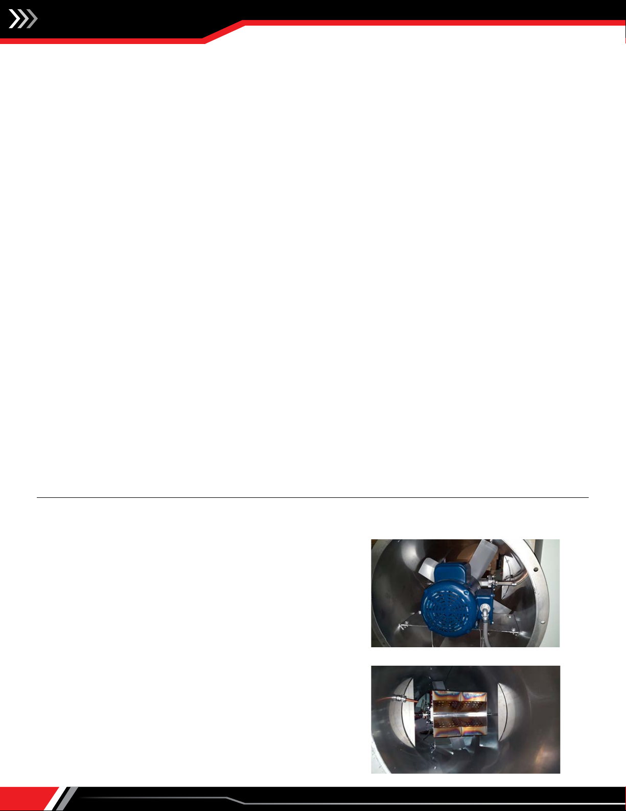
1. Direct Drive Axial Fan with Inlet Guard
2. Blower Motor
3. Direct Fired Burner
4. High Temperature Limit Thermostat – The high temperature
limit control prevents the burner from firing if excessive heated
air temperatures are experienced. The limit control is mounted
on the blower housing and is electrically interlocked with the
flame safeguard control (#3). The switch requires a manual reset
if tripped. Photo to the right shows high limit sensor.
Unit Features
Installation, Operation & Maintenance Manual IM-895
9
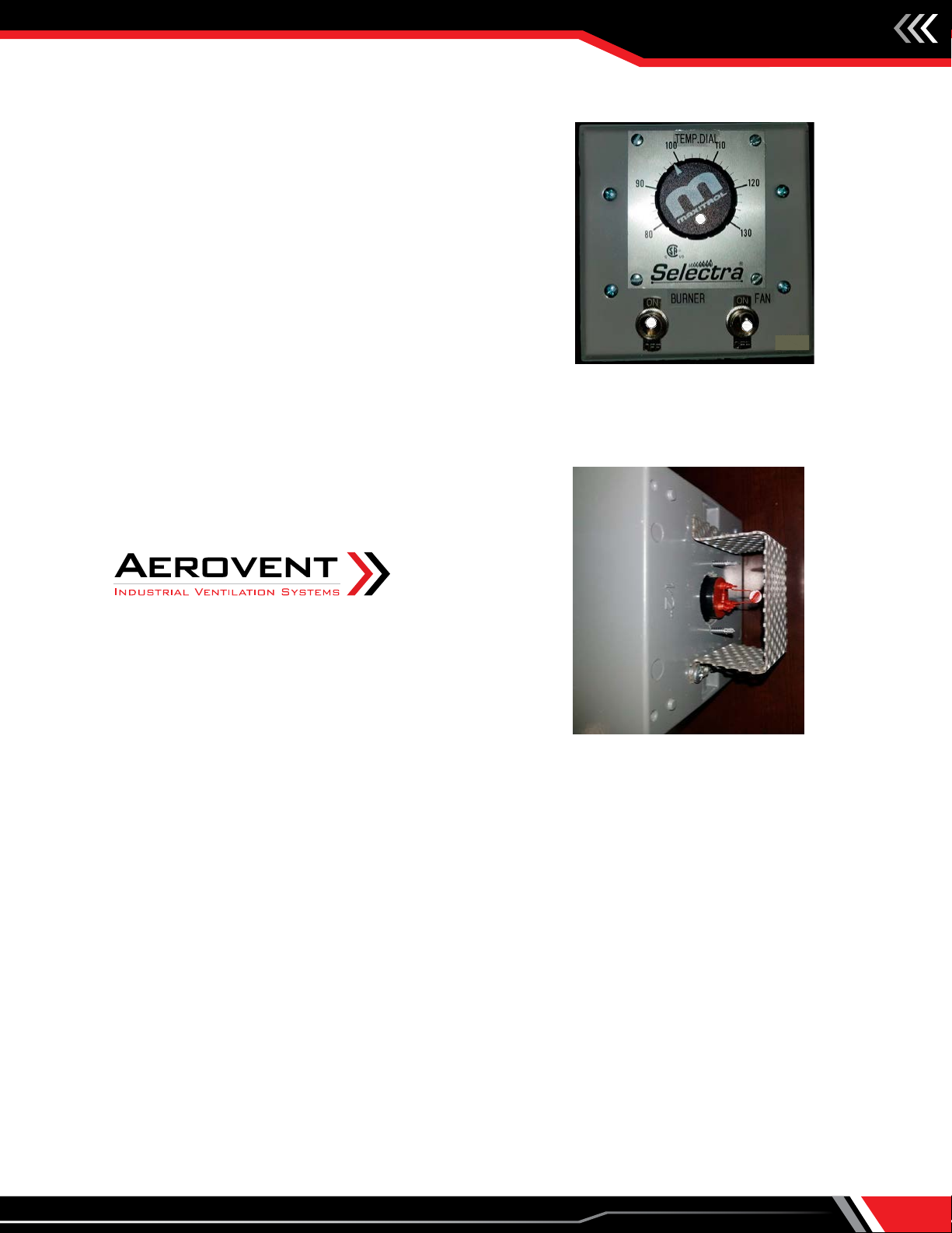
Accessories (Field Installed)
1. Remote Monitoring Panel – The remote monitoring panel
is used to control the operation of the door air heater.
Remote monitoring panel features include:
Fan Switch – All panels include a fan On/Off switch.
Burner Switch – All panels include a burner On/Off switch.
Temperature Control
• Discharge Temp Setpoint Dial: Maxitrol 14 units
1
2
3
REMOTE PANEL
Typical Remote Monitoring (Maxitrol 14 shown)
TEMP SENSOR
Temp Sensor Module
(Back of Remote Monitoring Panel)

Installation, Operation & Maintenance Manual
IM-895
10
Check, Test & Start-Up Procedure
Each unit is supplied with this Installation and Service Manual, which includes a Field Start-Up Form, starting on page 18. The Field
Start-Up Form must be followed and properly filled out by the installer, with one copy kept with the unit.
Before continuing with the start-up and checkout procedure, it is important to familiarize yourself with the controls and features
of the unit. Review the following:
• Documents shipped with the unit to determine which options/controls are included.
• Photographs, locations and descriptions throughout this manual for unit features, options, accessories and controls.
To properly perform the start-up, the following instruments are required:
• Ohm Meter
• Gas Pressure Gauge (range dependent on inlet pressure to unit)
• Slack Tube Manometer or 0-30" w.c. Pressure Gauge
• Inclined Manometer (0-5" w.c.)
• Handheld Tachometer (contact, reflective or strobe type)
Once a thorough review of these controls and devices has been made, the step-by-step Start-Up Procedure as described below
must be performed.
Pre-Start-Up Inspection
Although this unit has been assembled and tested at the factory, the following pre-operational procedures must be performed
to assure the unit is ready for operation.
1. Before proceeding, turn off all power to the unit. Turn all manual hand gas valves to the closed position.
• Remove all shipping straps, braces and tie downs.
• Perform a visual inspection of the unit to make sure no damage has occurred during shipment or installation.
• Check burner and fan impeller to ensure it is secure.
• Check all electrical connections for tightness.
• Check to ensure there are no obstructions to the inlet air supply or the discharge air supply.
• Check gas piping for leaks using a soap/water solution.
2. After these preliminary checks have been made, the unit can be prepared for start-up.
Performing the Start-Up
After the unit has been installed and the preliminary checks have been made from the previous section, the following start-up
can be performed.
1. Turn off all power to the unit. Turn all hand gas valves to the closed position.
2. Set the Burner On/Off and Fan On/Off switches on the remote-control panel to the "Off” position and set all thermostats to
their lowest settings.
3. Make sure all service doors are installed and/or closed.
1. If equipped with the factory installed disconnect switch option, when the switch is in the "OFF" position, supply power remains energized
at the supply power terminal strip and the top of the disconnect switch. When providing service on or near these terminals, building
supply power to the unit should be de-energized.
2. Proper air velocity over the burner is critical. If the velocity is not within the unit specifications, the unit will not operate efficiently, may
have nuisance shutdowns and may produce excessive carbon monoxide (CO) or other gases.
WARNING
NOTICE
Start-up and adjustment procedures should be performed by a
qualified service technician.
1. Do not operate unit with a gas input rate greater than that
shown on the unit's rating plate.
2. Purging of air from gas supply lines should be performed
as described in ANSI Z223.1-latest edition “National Fuel Gas
Code” or in Canada in Can/CGA-B149 codes.
CAUTION
Installation, Operation & Maintenance Manual IM-895
11
4. With the Fan On/Off switch still in the "Off" position, turn on the electrical supply to the unit.
5. Move the Fan On/Off switch to the "On" position (to activate the unit with heat disabled).
6. Check the blower for proper rotation per the airflow arrow on the blower.
7. Check the motor voltage. For three phase systems, check to make sure the voltage on all 3 legs vary less than 2%.
8. Check the motor Amp draw to be sure it does not exceed the motor nameplate FLA rating.
9. Measure the unit air volume being delivered and compare to the rated air volume on the unit serial plate. The most accurate
way to measure the air volume is by using a pitot traverse method downstream of the blower. Other methods can be used but
should be proven and accurate.
10.Recheck the gas supply pressure by installing a gas pressure gauge connected to the inlet gas pressure test port indicated on
the piping diagram included with the unit.
If the unit has an inlet gas pressure gauge, the pressure can be read directly from the gauge without needing to connect
a separate gauge. Refer to rating plate for proper gas supply pressure to unit. If inlet gas pressure exceeds the maximum
pressure specified on the rating plate, a gas pressure regulator needs to be added upstream of the factory furnished and piped
components.
Refer to the heater rating plate for determining the minimum gas supply pressure to obtain the full heating capacity for which
this heater is specified.
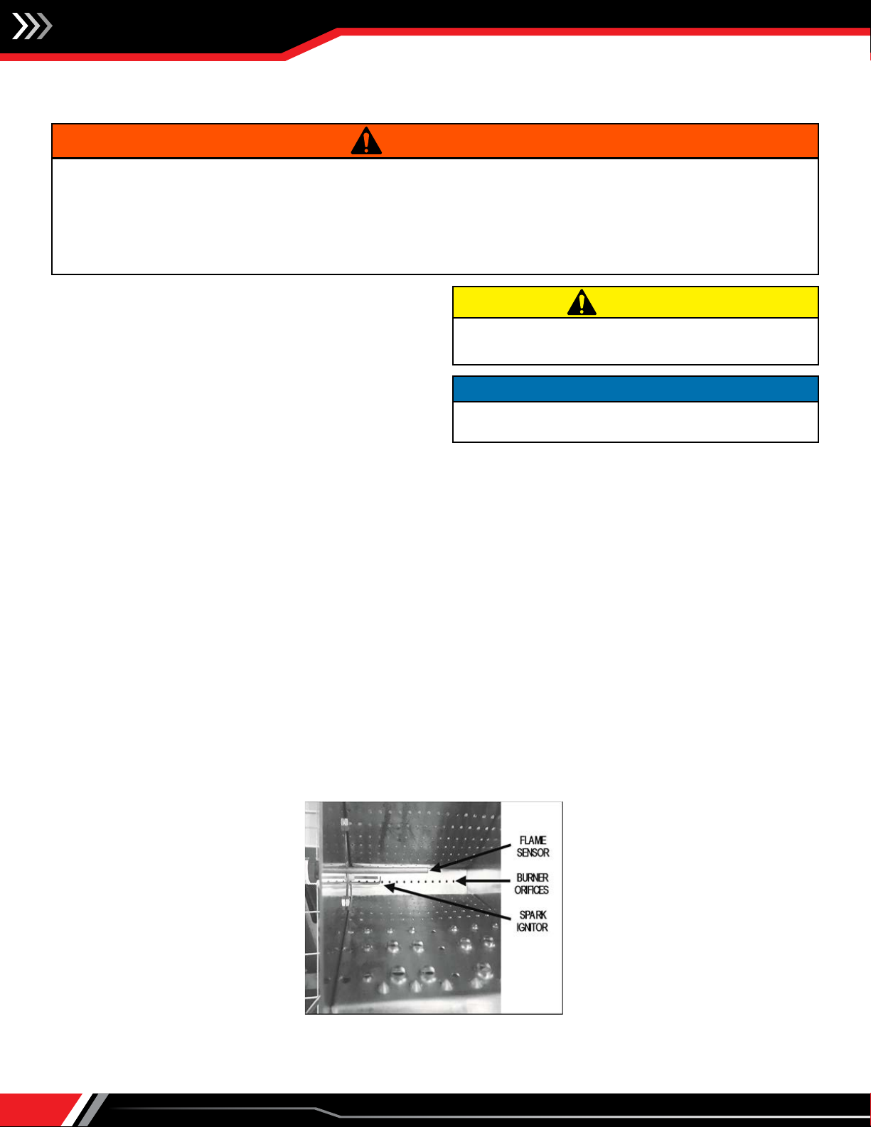
11. The unit includes Direct Spark Ignition (no pilot line), check the flame rod
flame sensor signal with the following steps:
a. Check that all manual reset safety devices have been reset to their
normal operating position.
b. Set the Burner On/Off switch to "On" and set the temperature controls
to call for heat.
d. The spark ignitor should begin to spark in approximately 10 seconds
and the burner flame should be established within 10 seconds.
12. Check the pressure differential across the burner profile per the following:
a. Remove the tubing plug from the burner gas pressure tap labeled
"BGPT" and connect an inclined manometer.
b. If the outdoor air temperature is below 60°F, fire the main burner to achieve a discharge air temperature of approximately
70°F. If the burner does not fire under these conditions, refer to the Troubleshooting Guidelines section of this manual for
additional guidance. If the outdoor temperature is 60°F or greater, do not fire the main burner.
c. Read the pressure differential reading on the burner pressure gauge or manometer. The actual installed pressure differential
reading must be 0.55" w.c. +/- 0.05" w.c. or 0.50" w.c. to 0.60" w.c.
d. If the differential pressure is out of range and cannot be achieved, contact the factory for additional guidance.
e. When the correct burner velocity pressure differential is verified, turn the unit off and open the main disconnect switch.
Remove the manometer and replace the tubing plugs in the burner gas pressure tap.
13.The high fire manifold (burner) pressure must be checked to ensure it matches the pressure shown on the unit serial plate.
Over-firing from high pressure can result in poor combustion and undesirable levels of combustion byproducts being
introduced to the heated space. The procedure is outlined in the following steps:
a. With the unit off, close the main gas manual hand valve. If not equipped with a burner gas pressure gauge, remove the
1/8" pipe plug test port at the burner and attach a water manometer or "U" tube that is at least 12" high. See piping diagram
furnished with the unit for pressure tap locations.
b. Start the unit and record the burner suction pressure present at the test port and record the negative number. Next, open
the gas valve and allow the burner to ignite (resetting the burner lockout if necessary). Observe the flame during the 10
second at low fire start to make sure it lights across the entire length of the burner and is stable with a clean blue flame.
c. Add the high fire pressure listed on the rating plate to the negative burner suction pressure recorded above. The resulting
sum is the actual measured gas pressure required for high fire in the next step.
d. Initiate a short (10-second) period of high fire. High fire can be achieved by removing wire 29 from terminal 4 on the
Maxitrol amplifier.
Check, Test & Start-Up Procedure (cont.)
Direct Spark Ignition Components
SIDE VIEW
INTO AIRFLOW VIEW
Installation, Operation & Maintenance Manual
IM-895
12
Check, Test & Start-Up Procedure (cont.)
If the actual measured pressure is within (+/-) 0.50" w.c. of the calculated burner pressure above, adjust the gas valve regulator
until the measured pressure matches the calculated pressure.
If the actual measured pressure is greater than 0.50" w.c. from the calculated burner pressure above, check the inlet gas
pressure to the unit. Adjust the main gas valve regulator to the correct inlet pressure within the range indicated on the unit
rating plate. Once corrected, repeat step #13 to measure the burner pressure.
e. With the high fire manifold pressure set to match the setting on the unit serial plate, observe the flame while in high fire.
The flame should be stable and burning clean. The flame should be predominantly blue, although a slight orange tip may be
present and is acceptable.
f. After the high fire pressure is correctly set, check the low fire burner flame. Install the wires removed in “d” above. Low
fire can be achieved by removing CR12 from its relay base.
g. Recycle the ignition sequence to make sure the burner lights smoothly and the flame is present across the entire length of
the burner.
14.With the unit off, close the main gas manual hand valve. If applicable, remove the "U" tube manometer and replace the 1/8"
pipe plug test port at the burner.
15.Test the gas seal of the safety shut-off valve(s) with the following steps:
a. While the unit is off, close the main gas hand valve and attach a pressure gauge to the downstream side of the last safety
shut-off valve (SSOV) closest to burner.
b. Open the main gas hand valve and following the startup procedure described in this manual, turn the unit on and allow the
burner to go to main flame.
c. Shut the unit off and let the pressure drop to zero.
d. Close the manual gas hand valve closest to the burner and wait 5 minutes. The main gas manual hand valve should remain
open.
e. There should be no changes in pressure. If the pressure increases, the second SSOV needs to be replaced.
f. Open the main gas manual hand valve.
Commissioning
After all the initial start-up procedures have been performed, the unit is ready for commissioning. Check the unit operation in
all modes against the General Sequence of Operation on the following pages or refer to the job specific sequence of operation
included with the unit as shipped.

Installation, Operation & Maintenance Manual IM-895
13
Sequence of Operation – General
The following describes the general sequence of operation for the unit. However, each unit may be slightly different based on
unit configuration and application. Each unit includes a laminated job specific Sequence of Operation affixed to the inside of the
control access door. Refer to that document for the actual unit Sequence of Operation.
Fan On/Off Switch = "Off"
The unit is shut down with no blower operation.
Fan On/Off Switch = "On"
1. With the blower motor control circuit energized, the motor starter contacts will close.
2. The gas and temperature controls are locked out to prevent heating during the Fan "On" mode of operation.
Burner On/Off Switch = "Off"
The unit is shut down with no burner operation.
Burner On/Off Switch = "On"
1. Before the ignition control sequence can be initiated, the following safety devices are checked for closure:
a. The airflow pressure switch ensures the airflow is at or below the maximum allowable to ensure clean combustion and
reduced flame disturbance.
b. The high temperature limit control ensures the supply air temperature does not exceed the maximum allowable limit for
safe operation.
2. With the safety devices described in the above steps verified, the flame safeguard control is enabled to initiate the ignition
sequence. After 10 seconds of pre-purge time, the ignitor is energized to produce spark ignition as follows:
• The main valve(s) opens and with the modulating valve at minimum position, the burner is allowed to light (direct spark
ignition).
3. The burner remains on low fire momentarily, then the temperature controls take over and fire the burner based on load
demands.
4. If any of the devices discussed in step #3 open, the gas circuit is disabled, the unit goes into lockout and the burner lockout
light is lit. Before resetting, a service person must inspect the unit, determine the cause and take corrective action.
Sequence of Operation – Blower
The blower control circuit is configured from the factory as initiated. The motor starter contacts will close and the blower motor
will operate at rated speed. The speed is fixed and not adjustable.
Final Step
With Start-Up and Commissioning complete, set the temperature controls for automatic operation if the unit is to be put into
service immediately.
If the unit is to be left off, set the On/Off switch to the “Off” position and turn the power off at the unit disconnect switch.
Installation, Operation & Maintenance Manual
IM-895
14
Maintenance (refer to safety section)
All heating equipment should be serviced before each heating
season to assure proper operation. The following items may
be required to have a more frequent service schedule based
on the environment in which the unit is installed and how
long the equipment is operated.
Motor Assembly
Check the motor sheave setscrews and the motor slide base
bolts for tightness upon initial start-up and before each
heating season. The motor bearings are pre-lubricated at the factory for initial operation but should be re-lubricated (when
provided with grease fittings) at six (6) month intervals. The recommended lubricants are Shell Oil Company "Dolium R", Chevron
Oil "SRI No. 2" or Texaco "Premium RB" lubricant. When lubricating, consider the following:
1. Clean the grease fitting and then apply the grease with a proper grease gun. Keep grease clean.
2. Use two full strokes for each bearing. Do not over-lubricate.
3. Do not mix petroleum grease with silicone.
4. Lubricate motors at standstill.
Burner
Annually, prior to each heating season, a check should be made of the burner and components. Clean the igniter and flame rod
and examine porcelain for cracks. Perform the following:
1. Inspect the burner carefully, including upstream and downstream sides of mixing plates as well as burner body face. Any
accumulation of scale or foreign material on either side of the mixing plates should be removed with a wire brush.
2. Add fresh di-electric grease (Grainger p/n 23YC40) inside the flame rod boot.
3. Check visually that no holes in the mixing plates are blocked. If any mixing plates are loose or missing fasteners, tighten/
replace as necessary. Always use zinc plated or stainless fasteners.
4. Check burner orifices for carbon build-up and clean. Use a pin vise with a #43 drill bit for Maxon NP-I burner orifices.
DO NOT ENLARGE BURNER ORIFICES – THIS MAY AFFECT PERFORMANCE.
When using a drill bit to clean the burner gas ports, do not
distort or enlarge the ports. Use a pin vise not a power drill.
CAUTION
1. Electric shock hazard. Could cause severe injury or death. Failure to bond the frame of this equipment to the building electrical ground
by use of the grounding terminal provided or other acceptable means may result in electrical shock. Disconnect electric power before
servicing equipment. Service to be performed only by qualified personnel. Make sure power is turned off and locked in the OFF
position.
2. If equipped with the factory installed disconnect switch option, when the switch is in the "OFF" position, supply power remains energized
at the supply power terminal strip and the top of the disconnect switch. When providing service on or near these terminals, building
supply power to the unit should be de-energized.
WARNING
Burner Orifices (Direct Spark Ignition shown)
NOTICE
Service and maintenance procedures should be performed by a
qualified service agency.

Installation, Operation & Maintenance Manual IM-895
15
Maintenance (cont.)
Gas Train
An annual inspection of the gas control assembly should be made. Internal and external piping should be checked for leaks. Relief
vents on gas controls should be checked for clogging.
Air Pressure Switches
An annual check of the tube for the airflow switch, and the entering and leaving side of building pressure switches, should be
made to ensure against blockage.
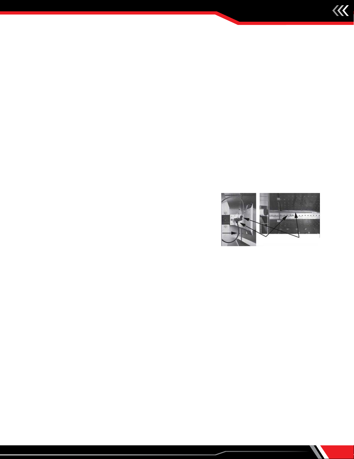
Discharge Air Sensor
Remove the cover from the sensor assembly junction box, which will expose the temp sensor module (see page 9). Remove the
two screws that hold the sensor module in the junction box. The sensor assembly junction box does not get removed. Insert a
bottle brush into the sensor sampling tube to clean out any dust or dirt, then replace the sensor module and junction box cover.
Gas and Electric Controls
Inspect for general cleanliness and tightness of electric and mechanical connections.
Put the system back into operation and view the burner from the downstream side while cycling the burner through its full firing
range. A good flame will be blue, with minimal yellow "fingers". The flame length in forced "high fire" should be 12-18" long.
Procedure for Extended Shutdown Periods
If the unit is to be shut down for an extended period of time, the following precautions should be followed:
1. Turn off all manual shutoff valve(s) in the gas train of the unit and in the gas supply line to the unit.
2. Turn off the electric supply to the unit at the unit disconnect. Lock the disconnect to prevent tampering.
3. Protect outside air openings to prevent the unit from being soiled.
Troubleshooting Guidelines
PROBLEM POSSIBLE CAUSE POSSIBLE REMEDY
A. Power Failure
1. Disconnect not turned on 1. Turn on disconnect
2. Blown fuses 2. Check and replace
3. Main to unit disconnect not on 3. Turn on power at main
B. Motor Not
Operating
1. Disconnect not turned on 1. Turn on disconnect
2. Blown fuses 2. Check and replace
3. Main to unit disconnect not on 3. Turn on power at main
4. Failed motor 4. Check and/or replace
5. Loose wiring to motor 5. Check and tighten
6. Motor overloaded 6. Check for proper speed
7. Improper supply voltage 7. Check and correct
8. Motor overheating 8. Check ring rate of unit
C. Blower Not
Operating
1. See Problems "A" and "B" 1. See Problems "A" and "B"
2. Broken drive belt(s) 2. Check and replace
3. Bearings seized 3. Check and replace
Do not reuse any mechanical or electrical component that has
been wet. Such components must be replaced.
CAUTION
NOTICE
To check most of the Possible Remedies in the troubleshooting
guide listed, refer to the applicable sections of the manual.
When servicing or repairing this equipment, use only factory-
approved service replacement parts. A complete replacement
parts list may be obtained by contacting the factory. Refer to
the rating plate on the unit for complete unit model number,
serial number and company address. Any substitution of parts
or controls not approved by the factory will be at owner's risk.
WARNING

Installation, Operation & Maintenance Manual
IM-895
16
Troubleshooting Guidelines (cont.)
PROBLEM POSSIBLE CAUSE POSSIBLE REMEDY
D. Burner Not
Operating
1. See Problems "A" thru "C". 1. See Problems "A" and "C"
2. Damper end switch not functioning 2. Check and/or replace
3. Failed air ow switch 3. Check and/or replace
4. Loose wiring connection at air proving 4. Check and tighten
5. No pilot 5. See Problem "F"
6. Flame safeguard in lockout mode 6. Check and reset
7. High limit tripped 7. Check and/or replace
8. Too high or low gas pressure 8. Check pressure switches and gas pressure
9. Failed control transformer 9. Check and/or replace
10. Blown control transformer fuse 10. Check and/or replace
11. Failed or malfunctioning main gas valve(s) 11. Check and/or replace
12. Faulty or failed freeze stat or inlet on/o stat 12. Check and/or replace
13. Failed safeguard control 13. See vendors instructions shipped with unit
14. Airow too low, low airow proving switch is
open
14. Check for reason of insucient airow and
correct
15. Airow too high, high airow cuto switch is
open
15. Check for reason of excessive airow and
correct
E. Flame Will Not
Prove
1. Inadequate signal to safeguard control 1. Check micro-Amps or Vdc from ame sensor
2. Insucient gas pressure to pilot 2. Check and adjust
3. Loose wires from ame sensor 3. Check and correct
4. Dirty ame rod 4. Clean and/or replace
5. Moisture on ame rod leads 5. Check and dry leads. Use di-electric grease inside
boot
6. Defective ame rod 6. Check and/or replace
7. Defective ame safeguard controller 7. Check and/or replace
8. Short in ame sensor leads 8. Check and/or replace
9. Excessive air velocity across burner 9. Check burner velocity and correct
F. Erratic
Temperature
1. Defective temperature selector or sensor 1. Check and/or replace
2. Temperature sensor subject to poor air ow or
located in drafty area 2. Check sensor location and move if required
3. Discharge sensor blocked by duct insulation 3. Check and remove blockage
4. Faulty amplier or modulating valve 4. Check and/or replace
G. Unable to
Achieve High Fire
1. Low gas supply pressure 1. Check and adjust
2. Modulating controls improperly set 2. See vendor literature shipped with unit
3. Faulty temperature sensor 3. Check and/or replace
4. Faulty amplier or modulating valve 4. Check and/or replace
H. Unable to
Achieve Low Fire
1. Modulating controls improperly set 1. See vendor literature shipped with unit
2. Faulty temperature sensor 2. Check and/or replace
3. Faulty amplier or modulating valve 3. Check and/or replace
I. No Gas Flow 1. Manual gas valve(s) closed 1. Open manual gas valve(s)
2. See Problem "D", Items 2 thru 13 2. See Problem "D", Items 2 thru 13
J. Unable to
Achieve Desired
Discharge
Temperature or
Space Temperature
1. Temperature sensors improperly set or faulty 1. Adjust or replace
2. Improper gas supply pressure 2. Check and correct
3. Faulty amplier or proportioning motor 3. See vendor literature shipped with unit
4. Airow too high 4. Check blower speed and/or burner velocity
dierential pressure
5. Burner capacity undersized 5. Check rating plate for conformance to design
specications

Installation, Operation & Maintenance Manual IM-895
17
Start-up Checklist and Report
Become familiar with the equipment by looking at the fan assembly drawing for
special instructions and accessories.
NOTICE
1. This Start-Up Check List and Report must be used in conjunction with the Installation and Service Manual originally shipped with the unit,
in addition to any other accompanying component supplier literature.
2. The use of this Start-Up Check List and Report is specifically intended for a qualified installation and service agency. All installation and
service of the unit(s) to which this applies must be performed by a qualified installation and service agency.
3. After completion of start-up, make a copy of this completed form for your files as necessary and leave the original copy with the owner
for future reference.
Project Information
Project Name:
Address:
City, State, Zip:
Equipment Information
Model #:
Serial #:
Start-Up Contractor Information
Company Name:
Contact Name (print):
Contractor Address:
Telephone #:
Owner Operation and Maintenance Review
Owner/Owner's Rep Name:
Title:
CUSTOMER'S AUTHORIZED SIGNATURE:
I acknowledge that I have been instructed on the operation and maintenance of this equipment.
Signature: Date:
Telephone #:
THIS MANUAL IS THE PROPERTY OF THE OWNER. PLEASE LEAVE IT WITH THE OWNER WHEN YOU LEAVE THE JOB.

Installation, Operation & Maintenance Manual
IM-895
18
Customer:
Sales Representative:
Model Number:
Serial Number:
FIELD START-UP SHEET
Direct Gas-Fired Equipment
INITIAL INSPECTION
I. Installer Responsibilities
1. Remote Panel (all interconnecting wires run from remote to unit): Yes N/A
Temperature control interconnect wires to remote ran in: Shielded Cable Separate Conduit
Remote Panel Location: ______ feet from unit (approx.) Inside Wall Outside Wall
PLEASE NOTE: If the Remote to Main Panel Interconnect Wiring is over 200' Long, Please Consult Factory!!
2. Gas supply connected with proper gas pressure regulator, drip leg, etc.: Yes No
3. Electrical supply connected with proper voltage/amperage, as stated on nameplate: Yes No
4. All electrical connections on all components are tight, including motor connections: Yes No
5. All "shipped loose" items installed properly (door switch, temp sensor, temp dial and gas valve assembly):
Yes No Comments:
II. Miscellaneous Items
1. Visible Physical Damage: No Yes
Explain:
2. Hardware Tight and Secure: Yes No
3. Damper Linkage Secure: Yes N/A
Comments:
III. Fan & Motor
1. Fan Secured Tightly to Motor Shaft:
2. Bushing Bolts Secure:
3. Motor Manufacturer: HP: FLA: Frame Size:
Comments:
Installation, Operation & Maintenance Manual IM-895
19
IV. Burner Inspection
1. Spark Igniter Secured Properly: 2. Flame Rod Secured Properly:
3. Ignition Wire Attached at Igniter and Transformer: 4. Unions Tight and Secure:
Comments:
V. Gas Manifold & Vent Piping
1. Manifold Assembly Components Tight and Securely Mounted:
2. All Fittings and Components Tight and Securely Mounted:
Comments:
VI. Electric Service
1. Electrical Service Provided to Unit: Volts Phase Hertz Amps
2. Unit Nameplate Electrical Requirements: Volts Phase Hertz Amps
3. Main Fusing Size (if applicable): Volts Amps
4. Overload Relay Setting (if applicable): Amps
5. Terminal Strip Wires Tight and Secure at: Main Panel: Yes Remote Panel: Yes N/A
6. Componentry and Relays Mounted Securely in Place: Yes
7. Unit has been grounded by installer at the main unit panel: Yes
Comments:
VII. Gas Service (see maximum and minimum gas pressure requirements on unit rating plate)
Natural Gas LP Gas Service Pressure: ________" w.c. - or- ________oz. - or- ________psig
Comments:

Installation, Operation & Maintenance Manual
IM-895
20
VERIFICATION OF OPERATION
NOTE: Refer to the Sequence of Operation & Wiring Diagram in the Owner’s Manual for specic data on this unit.
See Factory Start-up & Test Sheet in the Unit Owner’s Manual to note the unit settings prior to shipment.
I. Fan Operation
1. Fan Rotation is in the same direction as the rotation arrow (on fan):
Check the following:
Unit O Unit On/O Running (Burner O)
A-B _________Volts A-B _________Volts _________Amps
B-C _________Volts B-C _________Volts _________Amps
A-C _________Volts A-C _________Volts _________Amps
II. Burner Operation
4. The Prole Pressure Drop: __________ " w.c. (measured using high and low pressure ports)
5. The Burner Suction Static Pressure: __________ " w.c. (measured at the manifold pressure tap with unit fan on
and gas o)
6. The Burner High Fire Pressure: __________ " w.c. (measured as above, but with fan and gas on and unit in forced
high re)
7. The Service Pressure with burner in high re is: __________ " w.c. - or- ________oz. - or- ________psig
8. The High Temperature Limit Switch is eld set to: __________ ° F (maximum setting is 150°F)
9. Set the burner low-re gas pressure so there is a continuous "ribbon" of ame approximately 1" wide across face
of burner.
10. Flame Relay. If a Honeywell model, it should read 1.25 to 5.0 Vdc at terminals marked (+ -) on the ame relay
face, if Fireye, it should read 4.0 to 10.0 Vdc at terminals marked (+ -) on the ame relay face.
Verify the motor running
amps does not exceed
the motor nameplate FLA!
1. Enter "Gas Pressure Requireed at Burner for Max Rated Capacity" on rating plate ________" w.c.
3. The resulting pressure (________" w.c.) is the net
pressure required at the BGPT during High Fire
2. Subtract the Negative pressure measured at BGPT
when the fan is operating: ________" w.c.
Forcing High Fire
Δ – Maxitrol 14 System – Disconnect wire 29
Example: 4.6" w.c. on rating plate – 1.2" w.c. burner suction (measured with just fan running = 3.4" w.c. net measured at the BGPT.
Table of contents
Other Aerovent Heater manuals


Popular Heater manuals by other brands


Remington
Remington REM-221A-120 User's manual & operating instructions

Frico
Frico Thermozone AG 4000 A Series Assembly and operating instructions

Klarstein
Klarstein 10032004 manual

uniwatt
uniwatt UHC WCW Series owner's manual

ElectrIQ
ElectrIQ HS10-600-0.6DGW user manual

Webasto
Webasto DUAL TOP RHA 100 installation guide


