AETEK CH-200 User manual

CH-200 Powered Fiber Cable Transition Box
1. Use Power cables and Fiber cables.
2. Please avoid using low quality cables, which will seriously limit the cabling distance and power delivery.
Model Description
CH-200 12C ber panel with Power terminal block
IMPORTANT:
INTRODUCTION
PACKAGE CONTENTS
Quick Installation Guide
* 1x Quick Installation Guide * 1x Screw parts
RACKMOUNT INSTALLATION
P/N: 5019945200
Version : V1.0
1. General product information
This document provides the installation procedure for the Powered Fiber Cable Transition Box. The CH-200 is
designed to facilitate the transition from indoor rated Powered Fiber Cable to outdoor rated Powered Fiber Cable in a
neat and orderly fashion that maintains physical separation of the dierent media types.
2. Tools and additional items required
• Round Cable Stripper
• Electrical Wire Stripper
• Large Flat Screwdriver
• Small Flat Screwdriver
• Power Drill/Driver (as needed)
• Fiber optic termination and cleaning supplies
• 6 Port Fiber Adaptor in appropriate ber mode
• Furcation Tubing as required
3. Components
Cover
Fiber Spool
Ground Screw
Fiber Adapter
Cable Ties
CH-200

4. Description
The CH-200 contains the plenum rated transition box and cover, plenum rated cable ties. The CH-200 is designed to
accommodate up to six (6) PFC channels, with each channel consisting of two power conductors (+ and -) and one
duplex ber connection (TX/TR).
The CH-200 is designed for indoor use, and may be located in the plenum space. Cable can enter the box through
28.2mm hole. Excess ber can be safely managed and stored on the built-in ber spool.
5. Installation steps
Step 1 – Mounting and Grounding the CH-200
1.Attach 12 AWG (or larger) ground wire to the TB using the green ground screw as shown in Figure 1. Attach wire to
Earth ground.
2. Secure the ground wire to cable clamp with a supplied cable tie as shown in Figure 1.
6.Powered Fiber Cable Termination and Closeout
Step 1 – Route and terminate incoming/indoor Powered Fiber Cable
1. Route the incoming Powered Fiber Cable into the CH-200 and secure to the cable clamp with a supplied cable tie, as
shown in Figure 2. Ensure adequate length for ber slack (1-1.5 meters).
2. Strip the outer jacket of the PFC using a round cable stripper so that there is approximately 25mm of jacket extending
inside the box, as shown in Figure 3. Trim any strength members or other cable components except for power conductors
and bers.
Ground
Screw Terminal
Strip
Figure 1 Figure 2
Approx. 25mm of Cable Jacket
Figure 3
3. Cut the insulated power conductors to length. Strip o 5mm of insulation from the conductors using an electrical wire
stripper (12 AWG – 2.0mm; 14 AWG –1.6mm; 16 AWG –
1.3mm; 18 AWG -1.0 mm; 20 AWG– 0.8mm; 22 AWG – 0.65mm; 24 AWG – 0.5mm).
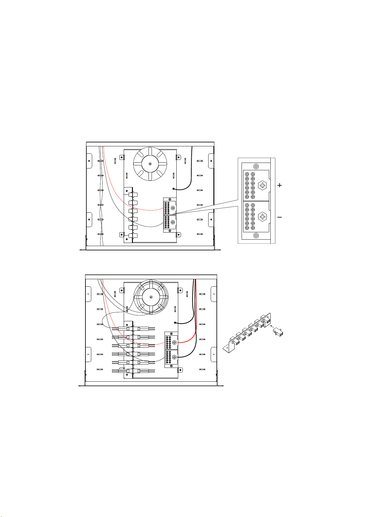
4. Match the wire polarity from the cable plant with the terminal strip polarity, as shown in Figure 4.
5. Using a small at screwdriver open the screw terminals until the wires insert into the terminal ports. Push each wire
into its port. Screw each terminal down hand tight to make contact between the terminal and the wire conductor. Verify
the wires are secure in the terminals with no exposed wire conductor, as shown in Figure 4.
6. Terminate the LC Fiber Optic plugs , Clean and install the LC terminations into the adapter Store excess ber on the
spool, as shown in Figure 5.
7. Repeat steps 1 – 5 for all incoming Powered Fiber Cable's
Step 2 – Route and terminate outgoing/outdoor Powered Fiber Cable
1. Route the outgoing Powered Fiber Cable into the CH-200 and secure to the cable clamp with a supplied cable tie, as
shown in Figure 6. Ensure adequate length for ber slack (1-1.5 meters).
2. Separate the cable into two sections along the tear lines
3. For the outgoing power termination repeat steps 3 – 5 from Section 6 Step 1, verifying any end device powered
equipment wiring polarity with polarity connections on terminal strip, as shown in Figure 6.
Note: Polarization indentation along one side of the cable for polarity identication
Figure 4
Figure 5

AETEK INC.
6F, No.192-1, Lien-Cheng Rd., Chung-Ho, New Taipei City, 235, Taiwan, R.O.C.
|T:+886-2-82452822|W: www.aetektec.com|E:[email protected]
All specications are subject to change without noice.
Copyright © 2023 AETEK INC. All rights reserved.
4. Terminate the LC Fiber Optic plugs per product specications instructions.
Note: Furcation tubing can be used to protect coated ber.
5. Clean and install the LC terminations into the adapter; see installation and cleaning instructions: TECP-96-194. Store
excess ber slack on the spool, as shown in Figure 11.
6. Repeat steps 1 – 5 for all outgoing PFCs.
Step 3 – Install CH-200 cover
1.Place the cover, tighten the cover screws to secure, as shown in Figure 7.
2.Install to 19" rack mount , as shown in Figure 8.
Figure 6
Figure 7
Figure 8
Table of contents
Other AETEK Surge Protector manuals


Popular Surge Protector manuals by other brands


Digitus
Digitus DN-95425 Quick installation guide
 installation manual")
RST
RST Power T2 3+1 275V (FM) installation manual

Eaton
Eaton BRSURGECSA Series Installation and operating guide

MTL
MTL HICKMAN EdgeBox RI installation guide

SECO-LARM
SECO-LARM Enforcer EVT-PB1-V1TSQ Specification sheet

Black Lion Audio
Black Lion Audio PG-2 owner's manual


