AEV Stargate User manual

AEV STARGATE
Futurcom Srl via della Tecnica 35, 40050 Argelato Bologna ITALY
1
AEV STARGATE
Stereo coder
&
Radio Data System
AEV STARGATE
Futurcom Srl via della Tecnica 35, 40050 Argelato Bologna ITALY
2
Guarantee
The equipment is warranted for a period of 2 years from the date of invoice (ex-works). The
warranty does not cover faults provoked by carelessness, natural causes and parts sub ect to
wear. In addition, the cost of labour and shipment is not covered. The warranty will be voided
if the equipment is mishandled.
Technical Support
If you require technical support, contact AEV SERVICE giving a clear and concise account of
your specific problem. Quote the serial number of your equipment by referring to the AEV
nameplate attached to the equipment itself as this is the most important piece of information
to be provided.
Telephone: 39+051+6634711 Fax: 39+051+6634700
Factory Service and Repairs
If problems arise while the equipment is being installed, consult this manual and check that
the installation is being carried out properly. If the problems still cannot be solved, call the AEV
SERVICE Department for further information. If the problem is a minor one we can a telephone
call will probably suffice. If, on the other hand, the equipment is to be shipped to AEV for
service or repairs, the AEV SERVICE Dept. will accept it only if the RMA return authorisation
number has been provided. This number must be included in the shipping documents. We also
recommend providing a detailed description of the fault which has occurred, the type of service
needed and (if required) the name of the employee at the AEV SERVICE Dept. you have
spoken to. No repairs will be made if the cost of shipment is charged to AEV. In this case, we
will not accept the delivery.
Shipping Instruction
When shipping the equipment to AEV, use the original package in order to be certain that it will
be fully protected during handling. If you need the original package, call us for a new one.
If you ship the equipment in a different packing container, take care to provide a double
package by interposing padding material between the two containers in order to fully protect
the equipment during shipment. The package should be marked "FRAGILE" in red.
Remember that the RMA number must be clearly visible on the package. If it is not, the
equipment will not be accepted.
SAFETY PRECAUTIONS
IMPORTANT: Carefully read this paragraph as it contains important instructions concerning
operator safety and directions regarding the installation, operation and maintenance of the
equipment.
Failure to observe the safety instructions and information given in this manual constitutes an
infringement of t e safety rules and design specifications provided for t is piece of
equipment.
AEV S.p.A. declines all responsibility if any one of the safety rules given herein is not
observed.
AEV S.p.A. declines all responsibility if the end-user resells the product.
The equipment is to be used by people capable of operating it in a trouble-free manner and it
is assumed t at t ey are aware of t e following safety rules.
• Keep this manual with the utmost care and close at hand so that it can be consulted
whenever needed.
• After unpacking the equipment, check it for condition.
• Avoid banging the equipment.
• The packing material (plastic bags, polystyrene, nails, etc.) must never be left within the
reach of the children, as t ese items are potential sources of danger.
• Do not use the equipment in places where the temperature is not within the recommended
range, as specified by the manufacturer.
• Before connecting the equipment, make sure the nameplate specifications correspond to the
mains electricity supply (the nameplate is located on the equipment enclosure).
• Do not remove the sticker from the equipment as it contains important specifications and the
relevant serial number.

AEV STARGATE
Futurcom Srl via della Tecnica 35, 40050 Argelato Bologna ITALY
3
• To oin the equipment to the mains supply, use the power cord purchased with the
equipment.
• The equipment must be used only for the purpose it was designed for.
• Abuse or misuse of the equipment is extremely dangerous for people, pets and property.
The manufacturer declines all responsibility for damage and in ury resulting from improper
use and mis andling.
• Certain basic safety rules must be observed when using electrical equipment, in particular:
- Never touch the equipment with wet and/or damp hands or other parts of the body.
- Keep the equipment away from drops of water or sprinkling systems.
- Never use the equipment near high heat sources or explosive material.
- Do not introduce any extraneous matter into the equipment.
- Do not allow children or untrained people to use the equipment.
• Before cleaning or servicing the equipment outside, disconnect it from the supply and wait at
least 2 seconds before working on it, as recommended by current safety regulations.
• In the event of faults and/or improper operation, turn off the equipment, shut off the
electrical power and call your dealer.
• Do not attempt to make repairs and/or ad ustments when covers/ guards or circuit boards
are to be removed.
• Blown fuses inside the power supply indicate that there may be a fault in the power supply
itself. The fuses must be replaced by qualified and authorised persons. It is advisable to call
your nearest dealer.
• Call your dealer for any repairs and be certain original spare parts are used. Failure to
observe t is rule may adversely affect t e safety level of your equipment.
• The equipment is to be connected to the mains supply and provided with adequate and
efficient earth conductors.
• The electrical wiring must be done in compliance with current electrical codes CEI 64-8
“Electrical specification for domestic buildings”.
• When installing, leave a clearance of at least 1 cm around the equipment to allow air to pass
freely.
NOTE. T is piece of equipment as been manufactured to t e ig est standards of
workmans ip. It must be used properly and serviced as recommended to ensure
long-term dependable operation.
RDS 4500 is an equipment that should be installed in a rack. The installation must be done in
order to be able to guarantee an easy access to the cable of feeding. The device of dissection
of the equipment is the cable of feeding, so it must be unconnected from the equipment every
time it is necessary to do any type of maintenance.

AEV STARGATE
Futurcom Srl via della Tecnica 35, 40050 Argelato Bologna ITALY
4
Contents
Guarantee ..............................................................2
Technical Support ......................................................2
Factory Service and Repairs ............................................2
Shipping Instruction ...................................................2
SAFETY PRECAUTIONS..................................................... 2
Contents….............................................................. 4
Introduction ............................................... .......... 5
General description ...................................... ............ 5
Initial power-up ...................................................... 5
Command Description ..................................... ............. 5
Front panel .............................................. ..... ...... 5
Rear panel .............................................. ............. 6
MultiCoder Adjustments ................................. .............. 6
Input level.................................................... ....... 6
Pre-emphasis............................................. ..............6
Baudrate RS32 .................................................. ...... 6
Pilot level................................................... ........ 6
Pilot phase................................................ ........... 6
L and R (Left and Right Enable) .......................... ............ 7
Mono / Stereo Mode .................................................... 7
Output level............................................... ........... 7
RDS level ......................................... ................... 7
Overview of the RDS service............................................ 7
SCA input level........................................... ............ 7
Configurations and in/out connections ................................ .7
Connections ................................................ ......... .7
Inputs/Outputs ............................................... ....... .7
Positioning of STARGATE ........................................ .......8
Overview of the RDS service .................................... .......8
- RDS - radiodata ..................................................... 8
Features RDS ......................................................... .9
Applications ..........................................................12
General Description ...................................................12
Definition of terms....................................................13
Program Identifier (PI) ...............................................13
Program Service name (PSN) ........................................... 13
Traffic Program identifier (TP) .......................................13
Alternative Frequency list (AF) .......................................13
Traffic Announcement identifier (TA) ..................................13
Program Type (PTY) ....................................................13
Decoder Identifier (DI) ...............................................13
Music / Speech (M/S) ..................................................13
Program Identification Number (PIN) ...................................13
Radiotext (RT) ........................................................13
Other Network information (EON) .......................................13
Transparent Data Channel (TDC) ........................................13
Clock Time (CT)........................................................13
Fast basic tuning and switching information ...........................13
Traffic Message Channel ...............................................14
Enanched Other Network (EON) ..........................................14
Linkage Information (LI) ..............................................14
Lenguage Identification Code (LIC) ....................................14
Extended Country Code (ECC) ...........................................14
Application Identifications (AI) ..................................... 14
Program Type Name (PTN).................................... .......... 14
Interconnection ...................................................... 14
RS232 Serial Port .................................................... 15
PC software........................................................... 15

AEV STARGATE
Futurcom Srl via della Tecnica 35, 40050 Argelato Bologna ITALY
5
Electrical Specifications ............................................ 30
INPUT................................................................. 30
STEREO Generator ....................................... ...... ...... 30
RDS Generator ........................................................ 31
Data Syncrhonization.................................................. 31
Remote I/O ........................................................... 31
General Data ......................................................... 31
Connection PC - RS232................................................. 31
Sample connection Remote ............................................. 32
Jumper & Dip Setting ................................................. 33
Preset dip ............................................................33
Setup dip .............................................................33
Introduction
General description
STARGATE is a digital stereo coder and RDS able to interface to any transmitter in common
use around the world.
The MULTI CODER STARGATE (stereo and RDS generator) uses a digital control circuit to
produce a system with an outstanding performance, high stability and total control of the
signal; amplitude and phase are both ad ustable to ensure optimal matching with all
transmission systems and the best possible stereo separation.
The RDS setup is also available via satellite.
Initial power –up
The Stargate inst ruct ion manual should be read carefully to ensure cor rect use of the unit .
1 . The STARGATE encoder`should be installed to qualify personel.
Connections between units must be as short as possible since reactive properties of the
connection cables will produce phase shifts on the multiplexed signal that will vary with
frequency. This will result in a reduction of stereo separation which can be severe.
It is recommended that connection cables do not exceed 3 metres in length.
2 . Position the encoder away from sources of heat.
Avoid humid sites with extremes of temperature.
3 . Check that the line voltage is suitable for the MultiCoder STARGATE before connection with
the cable supplied.
4 . Take care to ensure that input and output connections are made properly since, in the
ma ority of cases, hum and noise are caused by poor connections.
5 . Never use alcohol or chemical solvents to clean the unit as these can cause damage to the
finish.
6 . Should the unit appear faulty, switch off, the unit and contact your nearest AEV service
center.
7 . Keep this manual for future reference and to avoid possible operational error.
Failure to observe the above inst ruct ions will result in the immediate expiry of all
guarantees.
Command Description
Front panel
1. Indicator LED Power On/Off
2. 19 KHz pilot enable switch and indicator LED
3. MONO / STEREO MODE enable switch and indicator LED
5. RDS ON Indicator led
6. Compensation overshoot enable switch and indicator LED
AEV STARGATE
Futurcom Srl via della Tecnica 35, 40050 Argelato Bologna ITALY
6
7. Right channel insertion switch and indicator LED
8. Left channel insertion switch and indicator LED
9. Level meter
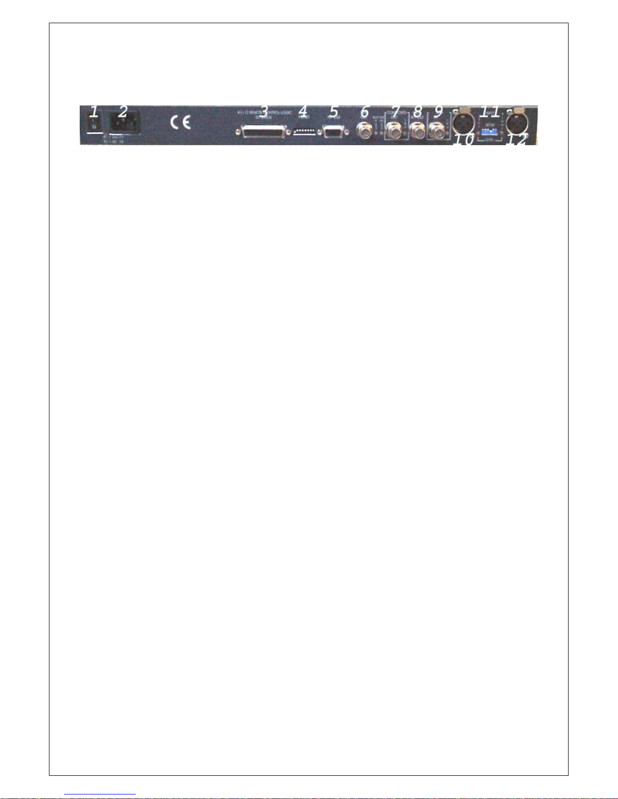
Rear panel
1. Switch On/Off
2. Line input connector, MAIN
3. Connector Remote for telecontrol
4. Dip-Switch to setup baudrate RS232
5. Connector RS232
6. RDS output signal Pilot phase ad ust Rds level ad ust
7. Composite signal output Composite level ad ust
8. 19 KHz input/output signal for locking of external systems
9. SCA signal input SCA level ad ust
10. Left channel input Left channel and level ad ust
10. AES/EBE digital input audio signal
12. Right channel input Right channel and level ad ust
Multi Coder Adjustments
Input level is the ad ustment for the input signal level; it may be varied using 2 multi-turn
trimmers. The input accepts signal levels from -10 to +10 dBu.
Pre- emphasis
The pre-emphasis setup can be selected via dip-switch "PRESET":
PRE-EMPHASIS
ON 50 µSec EUROPEAN standard
ON 75 µSec AMERICAN standard
OFF
See Technical Data section.
Baudrate RS 232
The serial baudrate setup mast be set by Dip-Switch on the rear panel "PRESET".
Pilot level
This controls the pilot signal level, relative to the amplitude of the MPX output signal.
The range available is between 4 and 12% of the optimum level (-20 dB with respect to 0 dBu
of the MPX signal. This is 10% of the signal which produces a deviation of ±75 KHz).
Pilot phase
This controls the phase of the 19 KHz pilot signal and allows the stereophonic separation to be
optimized by correcting for unwanted phase shifts introduced by transmission lines.
To optimize the stereophonic separation in the absence of a professional measurement
decoder, a receiver with a good stereo separation figure should be used as described in the
following procedure:
1. apply a music signal to the STARGATE inputs.
2. disable one channel e.g. left.
3. a signal will be present on only one channnel of the receiver.
4. reduce the level of the active channel on the receiver to zero and increase the level of the
other channel until a residual signal is detected.
5. minimize this signal by ad usting the pilot phase; the calibration is complete when a
minimum is achieved.
L and R ( Left and Right Enable)

AEV STARGATE
Futurcom Srl via della Tecnica 35, 40050 Argelato Bologna ITALY
7
These are the controls which enable the encoder’s L and R channels.
Press the switch to enable the L/R channels; the relevant led will illuminate.
Mono / Stereo Mode
This control enables and disables the coder modulator.
Pressing the STEREO switch changes between MONO and STEREO operation.
In the mono position the 19 KHz subcarrier is automatically disabled and the output becomes
equal to the average of the L and R channels: (L+R)/2.
Output level
Output level is the ad ustment for the input signal level; it may be varied using 2 multi-turn
trimmers.
The MPX output is ad ustable from 0 to +12 dBu.
The output RDS is ad ustable from infinite to -16 dBu.
The output should be ad usted for maximum permissable deviation at the transmitter
RDS level
RDS level is the ad ustment for the RDS signal level; it may be varied using a multi-turn
trimmer.
The RDS output is ad ustable from infinite to -16 dBu.
SCA input level
The points raised in the preceeding paragraph apply to this control apart from the range
which is from +6 to -14 dBu.
Configurations and in/ out connections
Connections
It is recommended that for input/output connections, a high quality flexible cable with a good
screen is used.
Special attention should be paid to the grounding of the unit and the quality of the line supply
ground connections. GROUND and CHASSIS connections between units should be kept
separate in order to avoid interference caused by earth loops.
Inputs / Outputs
The XLR inputs are electronically balanced with an input impedance of 10 k_.
The range of input levels is from -20 dBu to +10 dBu.
The output is unbalanced on a BNC connector situated on the rear panel. This output can
drive an impedance of 50 or 75 ohm at a distance of upto 100 m using RG 58 coaxial cable
before any appreciable degradation of the composite signal takes place.
The level can be ad usts in a range from 0 to +12 dBu.
An other input can accept SCA signal which may be regulated by trimmer and summed with
the MPX output signal.
An input or output are available for external synchronization (selectable via dip-switch
"PRESET"):
19 KHz IN 1 Vpp SqW ± 2 Hz for locking to external coders.
19 KHz OUT 1 Vpp SqW for locking by external coders.
Positioning of STARGATE
The best position for the STARGATE is as close as possible to the transmitter, in order to

AEV STARGATE
Futurcom Srl via della Tecnica 35, 40050 Argelato Bologna ITALY
8
minimize the distance between the two and thus reduce any distortion that could be
introduced by the cable.
The buf fered outputs of STARGATE can drive cable lengths of upto 100 m before any
appreciable distortion occurs to the MPX signal.
To guarantee the best transmission quality, all equipment used, should be carefully aligned
and capable of satisfying the appropriate requirements for bandwith, distorsion, signal path
delay and gain stability.
This equipment should be calibrated at regular intervals; the signal source should be lownoise,
have as flat a frequency response as possible from 30 ÷ 15,000 Hz and have a low
content of non-linear distortion.
Overview of the RDS service
There is a growing, global interest, both on the part of industry, as well as broadcasters, in
information systems which utilize a data channel inserted into radiophonic transmissions.
The interest in these new systems has been stimulated by the continuing evolution of radio
receiver technology which, with the introduction of LSI (large scale integration) circuitry and
the microprocessor, has allowed operation to be simplified and new possibilities to be offered.
Many of these new possibilities have been developed for FM (frequency modulation) radio
where, thanks to the bandwidth available, it is possible to insert an additional data channel
onto the subcarrier, whilst maintaining compatibility with the stereophonic transmission and
remaining completely inaudible.
By transmitting channel and program identification codes on the additional data channel, it is
possible to simplify the manual tuning of receivers and even make it fully automatic. This is of
particular benefit with today’s large and continuously growing number of FM radio stations. It
is also possible to receive up-to-date traffic news and offer other interesting features.
In the future, when radios will be fitted with voice synthesizers, it will be possible to transmit
traffic news (or other information) on the additional data channel as well as on the regular
program, as happens now, which will continue to be received uninterrupted and independently
of the data channel.
- RDS - radiodata
This system for the transmission of additional information on mono and stereo VHF (87.5-
107.5MHz), represents the most technically advanced and, for the huge range of possible
applications, the only that has any real chance of being adopted on a global basis.
It fulfils the various requirements needed by systems for the transmission of additional data on
radio programs, namely:
COMPATI BI LI TY WI TH THE MAI N PROGRAM
,
MONO AND STEREO
;
ABSENCE OF I NTERFERENCE ON ADJACENT
FM
CHANNELS
;
POTENTI ALLY BETTER COVERAGE AREA COMPARED TO MONO TRANSMI SSI ONS
COMPATI BLE WI TH OTHER I DENTI FI CATI ON SYSTEMS
,
ALREADY I N SERVI CE
.
Radiodata is the fruit of work undertaken by a specialized UER group, based on five proposals
formulated by Sweden, The Netherlands, Great Britain, Finland and France.
The superiority of this system results mainly from its protection from transmission errors,
crucial for in-car reception, high speed to synchronize the data groups, from its high data rate,
its potential for new applications and flexibility of use.
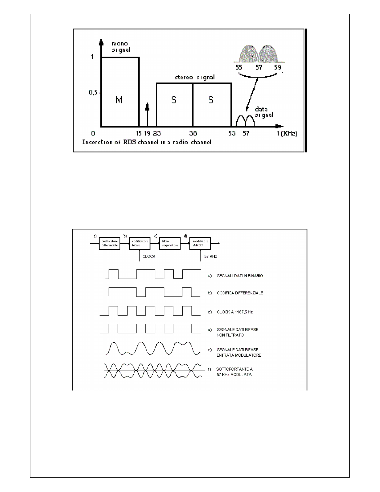
The spectrum of a multiplex, stereophonic signal, containing data is shown in fig.1.
AEV STARGATE
Futurcom Srl via della Tecnica 35, 40050 Argelato Bologna ITALY
9
Figure 1
The signal is transmitted by amplitude modulating, in suppressed carrier mode, a 57 KHz (3
times the 19 KHz pilot) subcarrier with a deviation of ± 2 KHz of the RF carrier, retaining
a maximum deviation of ± 75 KHz for the multiplex, composite audio/data signal.
Data transmission speed is 1187.5 bit/s and, being biphase coded, produces a spectrum of
about ± 2 KHz around the 57 KHz frequency which is suppressed-carrier modulated.
Carrier suppression is required to enable co-existance with ARI signals, since the latter
transmits information using narrow-band (about 250 Hz) DSB amplitude modulation.
The most important waveforms produced by this modulation are shown in fig.2 below.
To avoid phase ambiguity on recovering the 57 KHz subcarrier, in the case of coherent
demodulation, the binary data signal undergoes differential encoding prior to biphase
encoding.
Fig.3 gives an example of the 57 KHz subcarrier after modulation by the data signal.

AEV STARGATE
Futurcom Srl via della Tecnica 35, 40050 Argelato Bologna ITALY
10
Figure 3
The system satisfies the protection ratios specified by the CCIR for mono and stereophonic
transmissions.
Figure 4
Protection ratios for FM radiophony (max. deviation: ± 75 KHz)
Fig.5 shows the protection ratio curves for the three services.

AEV STARGATE
Futurcom Srl via della Tecnica 35, 40050 Argelato Bologna ITALY
11
Figure 5
The structure of the data signal is shown in fig.5.
Base-band structure of Radiodata
The structural element is the “group” containing 104 bits.
Each group comprises 4 blocks of 26 bits each, of which 16 are information and 10 are for
protection.
Each block is directly identifiable by an 8 bit word which is summed in module-2 with the 10
protection bits.
The transmission is completely synchronous and there are no interruptions between
consecutive groups and blocks.
Each block is protected by a self-synchronizing, compressed, cyclical code (26,16), having the
following properties:
DETECTS ALL SI NGLE AND DOUBLE ERRORS
;
DETECTS ERROR STRI NGS OF UP TO AND I NCLUDI NG
1 0
BI TS
;
DETECTS APPROXI MATELY
9 9 .8%
OF ERROR STRI NGS OVER
1 0
BI TS LONG
.
The code (26,16) performs well in correcting error strings which occur frequently in in-car
reception.
All error strings of upto 5 bits can be corrected.
It should be noted that the correction of reception errors implies a finite possibility of accepting
as correct, an incorrect message that has not been detected.
There is a choice, therefore, between simple error detection which will not recover the
message and full error correction which will do so.
From the results of reception tests carried out in Sweden, it would seem that the optimum
decoding strategy, both for domestic as well as in-car reception, requires correction of single
errors and ad acent double errors and the detection of long error strings.
The application of the error detection and correction code is however left to the receiver
manufacturer.
Features RDS
The principal features of this encoder are as follows:
· 50 PSN
· 100 AF LISTE
· RS 232 C
· DATE, HOUR and CT
· RADIOTEXT
· TA - PTY - MS
· Fast tuning and switching information
· Traffic Message Channel
· Enhanced Other Network
· Linkage Information
· Lenguage Identification Code
· Extended Country Code
· Application Identifications
· Program Type Name
· 19 KHz Input available on the rear panel

AEV STARGATE
Futurcom Srl via della Tecnica 35, 40050 Argelato Bologna ITALY
12
· Command TA - TA EON 0 - TA EON 1 - TA EON 2 - TA EON 3 - TA EON 4 - MS - RDS
OFFremote
available on the rear panel via Cannon 25 pin connector
· Enabling of transmitted groups (eg. RDS - CT - RADIOTEXT)
· Control of leap years
· RDS segnal level ad ust
Applications
Radiodata (RDS) has been developed principally for transmitting tuning information, such as
the channel identifier, for the control of radio networks and the control of basic functions of the
new generation of radio receivers. It also, however, offers basic ARI functions for in-car
reception besides many interesting possibilities for domestic radio reception.
For example, it will be possible to transmit a commentary to the main program, as a
RADIOTEXT message comprising text made up of alphanumeric characters (ASCII) that will
appear on a display integrated into the receiver, and ultimately be able to control a voice
synthesizer.
It is also possible to use Radiodata for the distribution of computer software.
It will thus be possible for software users to record software transmissions without the
inconvenience of often extended interruptions to the main program being transmitted.
General Description
Definition of terms
T
HE FOLLOWI NG LI ST OF DEFI NI TI ONS RELATE TO THE STANDARDI ZATI ON SPECI FI CATI ON ANTERI OR TO THE
EBU
TECHNI CAL DOCUMENT
- T
ECH
. 3 2 4 4 - E
AND
CENELEC
FOR
EN 5 0 0 6 7 .
Program Identifier ( PI )
This is a code which enables the receiver to distinguish the country of origin and the
identification of the transmitted program.
The most important application of this information is the ability for the receiver to search
automatically for alternative frequencies in the event of bad reception of the program to which
it is tuned.
The change of frequency happens when a better signal with the same code of PI (program
Identifier) is found.
Program Service name ( PSN)
This function allows transmission of messages upto a length of eight alphanumeric characters
which can be used by the receiver to display to the listener the name of the currently tuned
station and other information.
The Program Service name is not used for automatic searching.
Traffic Program identifier ( TP)
This is a function that identifies stations which transmit traffic information to drivers by, for
example, changing the colour of the receiver’s display.
Alternative Frequency list ( AF)
This function allows lists comprising 25 alternative frequencies to be transmitted. The receiver
can thus hop automatically to the best reception frequency of the transmission.
Traffic Announcement identifier ( TA)
When this function is enabled by the station, the receiver will switch automatically from
cassette to radio listening.
The car radio, as well as being tuned to the station transmitting traffic announcements, has to
be enabled to receive ARI INFO or TA.
Once the announcement has been made, the radio automatically reverts to cassette listening.
This function is analogous to ARI.
Program Type ( PTY)
This function allows a code corresponding to the type of program to be transmitted with the
program in order to identify it.
This service is not yet available on all receivers, but will eventually allow the receiver to be
programmed to record certain types of program.
31 categories of program have already been defined by the EBU and are listed as follows:
0. No program type or undefined
1. News
2. Current Affairs

AEV STARGATE
Futurcom Srl via della Tecnica 35, 40050 Argelato Bologna ITALY
13
3. Information
4. Sport
5. Education
6. Drama
7. Culture
8. Science
9. Varied
10. Pop music
11. Rock music
12. M.O.R. Music
13. Light classics
14. Serious classics
15. Other music
16. Weather
17. Finance
18. Children's programs
19. Social Affairs
20. Religion
21. Phone-In
22. Travel
23. Leisure
24. Jazz Music
25. Country Music
26. National Music
27. Oldies Music
28. Folk Music
29. Documentary
30. Alarm Test
31. Alarm
Decoder Identifier ( DI )
This function allows the identification of 16 different modes of operation including:
monophonic transmission
stereophonic transmission
artificial stereophonic transmission
processed mono
processed stereo
artificial processed stereo
Music / Speech (M/ S)
This function allows the program to be identified as music or speech.
Compatible receivers will have two controls for independant volume ad ustment of music and
speech to the listener’s preference.
Program I dentification Number ( PI N)
This function allows selection of program type by the listener, such as light music, news or
other.
Radiotext ( RT)
This function allows the transmission of 64 characters addressed to domestic receivers
equipped with a particular display.
With in-car receivers, where it is not possible to display text for safety reasons, it maybe
possible in the future to communicate the radiotext message using a voice synthesizer.
Other Netw ork information ( EON)
This service allows control of the TA, TP, PTY and PIN functions of ten radio networks.
Transparent Data Channel (TDC)
This service, which is similar to Radiotext, allows serial alphanumeric information,
correspondingto computer software or other non displayable information, to be transmitted.
Clock Time ( CT)
As per CCIR standards, information relating to time and date is defined by Coordinated
Universal Time (UTC) and by Modified Julian Day (MJD).
The listener will not have direct access to this information which will be used, internally, by the
receiver.
Fast basic tuning and switching information

AEV STARGATE
Futurcom Srl via della Tecnica 35, 40050 Argelato Bologna ITALY
14
Fast tuning service.
Traffic Message Channel
This service is used to send traffic information through a specific channel.
Enanched Other Netw ork ( EON)
This service transmits network information.
Linkage I nformat ion ( LI )
This information is transmitted together with the EON.
Lenguage I dent if icat ion Code ( LIC)
Language used by the radio station.
Extended Country Code ( ECC)
Specify oncemore the country name in order to be recognized inequivocably beside the
information already transmitted together with the PI.
Application Identifications ( AI )
Type of ODA signal to be transmitted together with the TMC.
Program Type Name ( PTN)
Specify the kind of PTY (example PTY=SPORT, PTN=BASEBALL max 8 characters).
Interconnection
The RDS data encoder must be connected between the stereo encoder and the transmitter.
The stereo encoder’s multiplex output should be connected to the MPX I N input of the RDS
encoder.
The MPX+ RDS OUT output should be connected to the input of the transmitter.
It is advisable to keep cable lengths to less than 3 metres.
The in ection of the RDS signal has been factory-ad usted for an MPX input level of 0 dBm (and
a 19 KHz pilot level of -20 dB).
For higher input signal levels, turn the “RDS LEVEL” multi-turn potentiometer clockwise.
This will increase the RDS signal level.
Internat ional standards recommend an RDS level of - 3 1 .5 dB w ith respect to the
stereo and consequent ly - 1 1 .5 dB w ith respect to the pilot .
No phase adjustment is required as synchronizationis per formed automatically by
internal circuitry.
In the event of monophonic transmissions, the RDS data encoder should be connected
betweenthe last low frequency unit in the audio chain and the transmitter.
Interconnection
The RDS data encoder must be connected between the stereo encoder and the transmitter.
The stereo encoder’s multiplex output should be connected to the MPX I N input of the RDS
encoder.
The MPX+ RDS OUT output should be connected to the input of the transmitter.
It is advisable to keep cable lengths to less than 3 metres.
The in ection of the RDS signal has been factory-ad usted for an MPX input level of 0 dBm (and
a 19 KHz pilot level of -20 dB).
For higher input signal levels, turn the “RDS LEVEL” multi-turn potentiometer clockwise.
This will increase the RDS signal level.
I nternat ional standards recommend an RDS level of - 3 1 .5 dB w ith respect to the
stereo and consequent ly - 1 1 .5 dB w ith respect to the pilot .
No phase adjustment is required as synchronizat ion is per formed automat ically by
internal circuit ry.

AEV STARGATE
Futurcom Srl via della Tecnica 35, 40050 Argelato Bologna ITALY
15
In the event of monophonic transmissions, the RDS data encoder should be connected
between the last low frequency unit in the audio chain and the transmitter.
RS232 Serial Port
The Serial connection RS232C is standard and has a 9 poles Cannon connector.
As per each RS232 connection, the length must not be superior to 20 m and the shielding
must be adequate.
Anyway, it is possible to extend the connection at any time by using a couple of standard line
extensors.
Pc Software
The RDS coder control program is supplied together with this handbook in CDROM
version. It must be installed on a computer with CPU Pentium 266 or better and a
Windows 95/98 version must be installed. The software cannot run without these
configurations or, in the best of cases, it will run but will not be able to communicate
correctly with the coder.
To install the program, go to the CDROM reader drive, and double click on the Setup.exe icon.
The program will be automatically installed and a link will be created on the program bar.
To execute the program, click on the Star t button on the applications bar with the left button
of the mouse. Select the Programs file, then the Rdspcsat file. Now, using the mouse, click
on the Rdspcsat program.
The following window will appear:
An error message may be received when the program is started for the first time, due to the
default parameters set, which may not be suitable for your system. The parameters of the
serial port must therefore be modified.
AEV STARGATE
Futurcom Srl via della Tecnica 35, 40050 Argelato Bologna ITALY
16
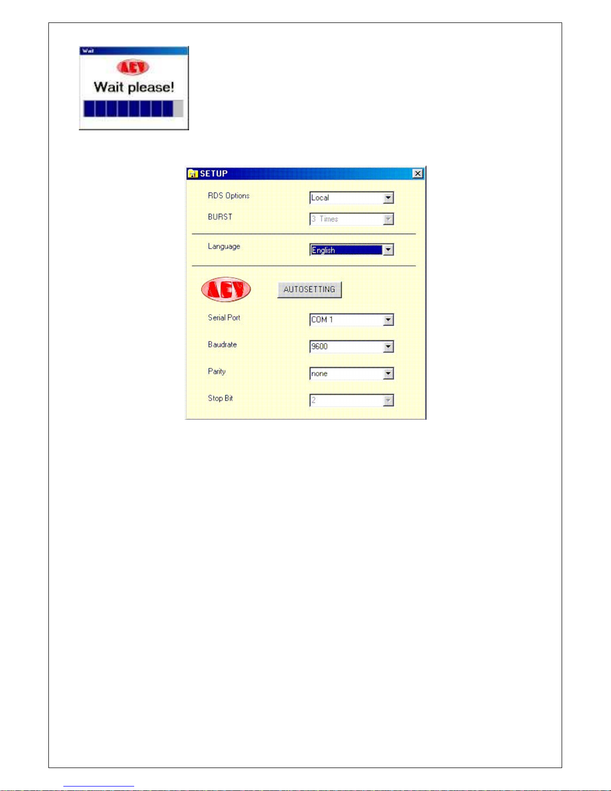
Select the RS232 icon and the following window will appear:
Let’s now see the parameters and their meaning:
- RSD Option
this is used to choose whether a coder programmed locally or via satellite is involved.
This choice affects all the programming windows and disables or enables certain functions.
In the case of programming "via satellite", only the transmission function is available therefore
all the reading push buttons will be disabled. A new push button called BURST will also be
enabled, which automatically repeats the transmission performed a number of Times, equal to
that set in the specific option.
This performance has been implemented to overcome the problem of any "MTF’s" transmitted
with the consequent incompleteness of the parameters sent.
- BURST
3 Times 4 Times ..... 10 Times as explained above, this parameter takes care of the
transmission, repeating it 3, 4 ....10 times.
- LANGUAGE
Choice of the operational language.
- AUTOSETTI NG
This push button is enabled only in the “Local” configuration and automatically searches
the communication parameters of the serial port. It may in any event always be entered
manually.
- Ser ial Por t
Choice of the communication port: COM1, COM2, COM3 or COM4.
- Baudrate
Choice of the transmission speed. It must be set according to all set on the dipswitches of
the coder.
It may assume the following values: 2400, 4800, 9600 or 19200
- Parity
Choice of the parity, which may take on the following values: none, even or odd
AEV STARGATE
Futurcom Srl via della Tecnica 35, 40050 Argelato Bologna ITALY
17
- Stop Bit
This parameter may not be altered. It is used to display the status of the "Stop Bit".
For connections in downlink from satellite mode, a baud rate of 9600 must be set unless
requested otherwise in the technical specifications of the satellite downlink..
Once the communication parameters have been set, communication must be enabled with the
coder, by sending it an address (default setting=?????).
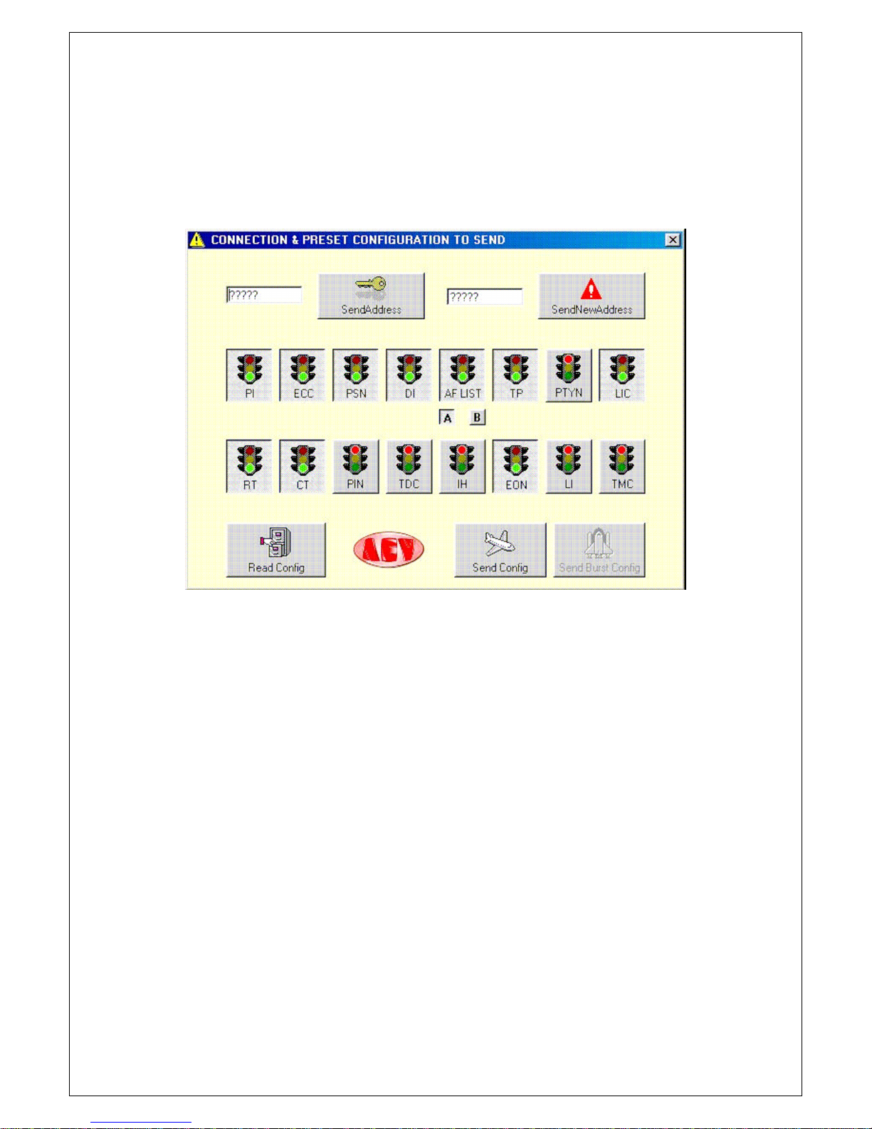
Press the Connect ion push button to gain access to the code send and change menu, together
with a set of push buttons used to send or read certain categories without entering the
appropriate window.
Let’s see the parameters and their meaning.
A box at the left hand part is displayed where the coder address is entered. The default
address is ?????.
The Send Address push button at the side of this text box is used to activate the coder for
programming, whether this is done “locally” or “via satellite”.
Another text box and a push button on the right hand part are used to change the address
of the coder (this operation is normally done only for applications via satellite).
16 push buttons are available (On/Off), which gather the functions of the RDS coder. The
functions in ON status (green traffic light) can be transmitted or read simultaneously.
Two small square push buttons under the AF switch are used to select the type of
transmission of the alternative frequencies.
The small A push button is used to program a single list made up of a maximum of 25
frequencies, which are reduced by one each time the frequencies type xxx.250, xxx.750
are enabled. This is the only system that allows the enabling of frequencies with 25KHz
steps.
The small B push button is used to program up to 50 lists, each of which is made up of a
maximum of 12 pairs of alternative frequencies.
Three push buttons are available in the part underneath. In “local” configuration, Read Config
and Send Conf ig will be enabled, which are used to send or to read the options selected by
means of the “traffic lights”. In “satellite” configuration, Send Config and Send Burst will be
enabled, which are used to send the options selected by means of the “traffic lights”.
Exit this menu to return to the main Menu.
At this stage, it is a good rule to save the parameters set so far using the relative push
buttons. NEW is used to create a new file (with the default parameters), OPEN to open an
existent file and SAVE to save the file in use or to re-name it. It is advisable to give the
configuration file (rds), a name different from RDSPCSAT.rds, OldLocal.rds and Full.rds as
these are the names of those already existing.
Let’s analyse the PSN-RT-PIN-AF-PTYN push button parameters. From the main menu, by
AEV STARGATE
Futurcom Srl via della Tecnica 35, 40050 Argelato Bologna ITALY
18
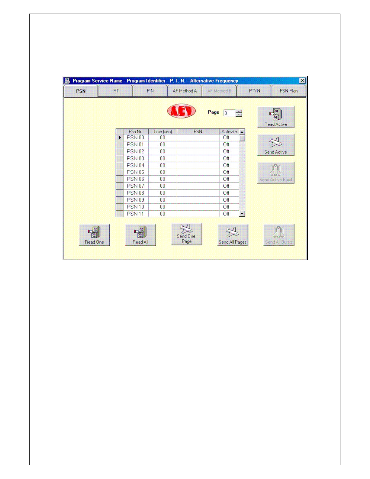
pressing the push button with a PC, a menu of boards will appear. By clicking on the tab of
the board, the option to be modified can be selected. The first board illustrated will be that
of the Program Service Name.
From here onwards all the windows that appear will refer to a "local" coder. If we were working
in the via "satellite" mode, all the Read’s would be disabled, whereas the Burst push button
would be enabled.
Up to 50 PSN’s can be programmed. Programming is quite simple. Enter the Time
( se c) (transmission time in seconds) of each PSN (it is advisable to enter a time of less
than 3 sec). Edit the PSN, which may have a length of 8 characters, including spaces.
Finally enable the PSN by double clicking on the Act iva t e box of this PSN.
The number of the PSN page can be selected in the Page box (from 0-9), which can be sent to
the RDS by programming the PSN Plan.
Let’s see what the push buttons are used for.
Read One reads the PSN selected.
Read All reads all the PSN’s of the page selected.
Send One Page sends the PSN selected.
Send All Page sends all the PSN’s of the page selected.
Read Act ive reads the page being transmitted by the rds coder.
Send Act ive sends the page displayed, which will be immediately transmitted on the rds coder.
Let’s examine the programming of the Radio Text. As described earlier, click on the
board Radio Text tab.
The following window will be displayed.

AEV STARGATE
Futurcom Srl via della Tecnica 35, 40050 Argelato Bologna ITALY
19
Following the same programming procedure as that for the PSN, enter the transmission
Time (sec) of the string of characters then, in the Radio Text box, enter the text of up
to 64 characters. Up to 50 strings can be entered.
Let’s now analyse the options of the P.I.N. board.
Enter the date of the Day when the programming is to be made.
Enter the programming beginning Time.

AEV STARGATE
Futurcom Srl via della Tecnica 35, 40050 Argelato Bologna ITALY
20
Select the programming mode amongst those offered. Now, going on to a new setting,
the 4-figure PIN code will automatically be created. The last box shows whether the
setting has already been made (Yes) or whether it is still to be processed (No).
Two different boards for programming the alternative frequencies will now be shown, according
to the mode selected: AF Method A or AF Method B.
Bear in mind that the use of one method excludes the other.
Let’s now analyse the AF Method A board.
This board consists of 25 frequencies. Only with this method will it be possible to enter
frequencies with steps of 25 KHz. The last of this type of frequency causes the loss of another
frequency: therefore up to 25 frequencies with steps of 50 KHz can be entered or 12
frequencies with steps of 25 KHz or in a combined manner, taking all explained earlier into
account.
Once all the frequencies have been entered, the setting can be sent to the coder using the
Send push buttons. If the “local” mode is being used, the parameters already set may also be
read.
Table of contents


