Datexel DAT 4530 User manual
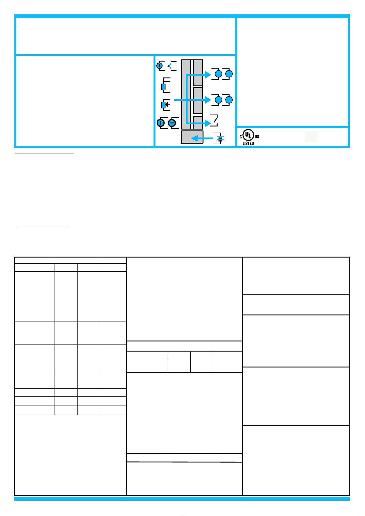
4-20mA Current Splitter
Phone: +1 561 779 5660 E-mail : [email protected] - Web Site www.datexel.com
DAT 4530
DAT 4530
Universal isolated converter
configurable by Dip-Switch or C
double output & trip amplifier
TECHNICAL S ECIFICATIONS (Typical @ 25 °C and in nominal conditions)
Line resistance influence (1)
TC, mV <=0.8 uV/O m
RTD 3w (50W max balanced) 0.05%/W
RTD 4w (100W max balanced) 0.005%/W
Linearity (1)
TC, RTD ± 0.1 % f.s.
mV, V, mA ± 0.05 % f.s.
Thermal drift (1)
Full scale ± 0.01% / °C
CJC ± 0.01% / °C
RTD excitation current
RTD, Res 400 uA
CJC Comp. ± 0.5°C
Input impedance
TC, mV >= 10 MW
mA ~22 W
Aux. Voltage >18V @ 20mA
ALARM TRI (SSR)
Contact SPST
Max Load (resistive) :
Voltage 48 Vdc / 30 Vac
Current 0.4 A
Aux. Voltage >12V @ 20mA
FEATURES
- Universal configurable input for:
mV, Tc, RTD, Res, otentiometer, V and mA
- Two outputs configurable in current or voltage
- Trip alarm
- Configurable by dip-switch or C
- High accuracy
- On-field reconfigurable
- Galvanic isolation among all the ways
- UL / CE mark
- Suitable for DIN rail mounting in compliance
with EN-50022 and EN-50035
GENERAL DESCRI TION
T e universal isolated converter DAT 4530 is able to measure and linearise voltage, current and resistance signals, potentiometers and t e standard
t ermocouples and RTDs wit , if required, t e cold junction compensation, t e wires compensation. For mV, V and mA input it is possible to set an
option for t e fast sampling (option HS) or to extract t e square root of t e measured signal (option SQRT). In function of programming, t e measured
values are converted in a current or voltage signal on t e two outputs. Moreover an output contact is available as trip alarm.
By dip-switc es accessible opening t e window on t e side of t e enclosure, it is possible to select t e input type and range and t e output type wit out
recalibrate t e device.
By Personal Computer t e user can set t e two outputs wit independent settings, t e parameters of t e Trip Alarm and t e optional parameters for is
own necessity;
T e galvanic isolation between input, outputs and power supply eliminates t e effects of all ground loops eventually existing and allows t e use of t e
converter in eavy environmental conditions found in industrial applications. T e device guarantees ig accuracy and performances stability bot
versus time and temperature.
T e DAT 4530 is in compliance wit t e Directive UL 61010-1 for US market and wit t e Directive CSA C22.2 No 61010-1 for t e Canadian market.
It is oused in a plastic enclosure of 12.5 mm t ickness suitable for DIN rail mounting in compliance wit EN-50022 and EN-50035 standards.
USER INSTRUCTIONS
T e connections must be made as s own in t e section "Connections".It is possible to configure t e converter on field by dip-switc or Personal
Computer as s own in t e section “ Programming ". T e configuration by dip-switc es can be made also if t e device is powered (note: after t e
configuration t e device takes some seconds to provide t e rig t output measure ).
Output type Min Max Min Span
Output resolution
Current 7 uA
Voltage 4 mV
Burn-out values
Max. output value 22 mA or 11 V
Min. output value 0 mA or -0.6 V
Current 0 mA 20 mA 4 mA
Voltage 0 V 10 V 1 V
Response time (10÷ 90%) about 400 ms
100 ms (option HS)
Output load Resistance - Rload
Current output < 500 W
Voltage output > 10 KW
S ort circuit current 30 mA max.
OUT UT (2 CHANNELS)
MECHANICAL S ECIFICATIONS
Material Self-extinguis plastic
IP Code IP20
Wiring wires wit diameter
0.8÷2.1 mm2 /AWG 14-18
Tig tening Torque 0.8 N m
Mounting in compliance wit DIN
rail standard EN-50022
and EN-50035
Weig t about 90 g.
Power supply voltage 20 .. 30 Vdc
Reverse polarity protection 60 Vdc max
Current consumption
Current output 90 mA max.
Voltage output 30 mA max.
ISOLATION
Among all t e ways 1500 Vac,
50 Hz, 1 min
OWER SU LY
Input type Min Max Span min
Accuracy (1)
mV, TC t e ig er of ±0.1% and ±12 uV
RTD t e ig er of ±0.1% and ±0.2°C
Res. t e ig er of ±0.1% and ±0.15
Potentiometer ± 0.05 % f.s.
Voltage t e ig er of ±0.1% and ± 2 mV
mA t e ig er of ±0.1% and ± 6 uA
mV, V, mA ± 0.5 % f.s (opt. HS)
RTD (2, 3, 4 wires)
Pt100 -200°C 850°C 50°C
Pt1000 -85°C 185°C 30°C
Ni100 -60°C 180°C 50°C
Ni1000 -60°C 150°C 30°C
RES. (2, 3, 4 wires) 0 W 500 W 50 W
0 W2000 W 50 W
IN UT
Voltage -10 V 10 V 1 V
TC (CJC int./ext.)
J -200°C 1200°C 100°C
K -200°C 1300°C 100°C
S 0°C 1750°C 400°C
R 0°C 1750°C 400°C
B 0°C 1850°C 400°C
E -200°C 1000°C 100°C
T -200°C 400°C 100°C
N -200°C 1300°C 100°C
Voltage
mV -100 mV +90 mV 5 mV
mV -100 mV +200 mV 10 mV
mV -100 mV +800 mV 20 mV
(1) referred to t e input Span (difference between max. and min.)
ot. (Rnom.< 50KW) 0 %100 % 10 %
Current 0 mA 20 mA 1 mA
RTD/RES VmA
VmA
TcmV
mA
V
ot
Alarm
DC SU LY
+
-
ENVIRONMENTAL CONDITIONS
Operative Temperature -20°C .. +60°C
UL Operative Temperature -10°C .. +60°C
Storage Temperature -40°C.. +85°C
Humidity (not condensed) 0 .. 90 %
Maximum Altitude 2000 m
Installation Indoor
Category of installation II
Pollution Degree 2
CERTIFICATIONS
EMC ( for industrial environments)
Immunity EN 61000-6-2
Emission EN 61000-6-4
UL
US Standard UL 61010-1
Canadian Standard CSA C22.2 No 61010-1
CCN NRAQ/NRAQ7
Typology Open Type device
Classification Industrial Control
Equipment
File Number E352854

87654321
87654321
SW1 SW2
Input type
Out B Full scale Zero
OFF
ON
- Input type Pt100
- Option 3 wires
- Out A 4-20 mA
- Out B 0-10 V
- Full scale 200 °C
- Zero -50 °C
EX. of configuration SW1 =
SW2 =
SW3 =
4321
SW3
Out AOpt
CONFIGURATION BY C
By software DATESOFT it is possible to:
- set t e default programming of t e device;
- program t e options not available wit t e dip-switc ;
(burn-out level, CJC offset, trip alarm settings, fast sampling, etc...);
- read, in real time, t e input and output measures;
- follow t e dip-switc es configuration wizard.
To configure t e device follow t e next steps:
1) Power-on t e device.
2) Open t e protection plastic label on t e front of t e device.
3) Connect t e interface PRODAT to t e PC (COM port)
and to t e device (PGRM connector).
4) Open DATESOFT.
5) Select t e COM port in use.
6) Click on “Open COM”.
7) Click on t e icon “Program”.
8) Set t e programming data.
9) Click on t e icon “Write” to send t e programming data to t e device.
Warning: during these operations the device must always be powered and the TX/RX cable always connected.
For information about D TESOFT refer to the software's user guide.
J1
TX/RX CABLE
RODAT
COM ORT
.C.
V+ V-
UV
GRM
lastic label protection
DAT
OWER SU LY
UNIT
ROGRAMMING
CONFIGURATION BY DI -SWITCHES
1) Open t e suitable door on t e side of t e device.
2) Set t e input type by t e dip-switc SW1 [1..5] (see TAB.1)
3) Set t e output A type by t e dip-switc SW1 [7..8] and SW2 [1..2] (see TAB.2)
4) Set, if available, t e input option by t e dip-switc SW1 [6] (see TAB.3)
5) Set t e minimum input scale value (Zero) by t e dip-switc SW3 [1..4] (see TAB.4)*
6) Set t e maximum input value (Full scale) by t e dip-switc SW2 [3..8] (see TAB.4)*
NOTE:
- It is also possible to set t e dip-switc es using t e wizard of t e
configuration software following t e procedure described in t e section
”Configuration by PC” until t e step 6 and clicking on icon “Switc ”.
THRESHOLD O ERATION
For t e ig alarm t e relay goes on w en t e input signal is ig er t an
t e trip level and after t e delay time. T e relay goes off only w en t e
input signal is lower t an t e trip level minus t e ysteresis value or w en
reac es t e minimum value of t e input scale and after t e delay time.
For t e low alarm t e relay goes on w en t e input signal is lower t an t e
trip level and after t e delay time. T e relay goes off only w en t e input
signal is ig er t an t e trip level plus t e ysteresis value or w en
reac es t e maximum value of t e input scale and after t e delay time.
T(delay) T(delay)
Active relay
Trip level
Trip level - yst.
T(delay) T(delay)
Active relay
Trip level
Trip level + yst.
HIGH ALARM THRESHOLD LOW ALARM THRESHOLD

Zero
SW3
321
Default
-200
-100
-50
-40
-30
mV-°C
TAB.4a – mV, Tc input scale settings
Full scale
SW2
6543
Default
0
5
10
15
20
25
30
35
40
45
50
55
60
65
70
mV-°C
7 8
SW2
75
80
85
90
100
110
120
130
140
150
160
170
180
190
200
mV-°C SW2
250
255
275
300
325
350
375
400
425
450
475
500
550
600
650
mV-°C SW2
700
750
800
850
900
mV-°C
950
1000
1100
1200
1300
1400
1500
1750
1800
-60
-80
225
95
4
-20
-10
0
50
100
150
20
10
1600
1850
6543 7 8 6543 7 8 6543 7 8
Zero
SW3
4321
Default
-200
-150
-40
-30
-20
-10
0
5
10
20
30
50
100
°C
Full scale
SW2
6
543
Default
0
5
10
15
20
25
30
35
40
45
50
55
60
65
70
°C
7 8
SW2
6
543
75
80
85
90
95
100
110
120
130
140
150
160
170
180
190
°C
7 8
SW2
220
230
240
250
260
270
280
290
300
310
320
330
340
350
°C SW2
380
390
400
°C
425
450
475
500
525
550
600
800
850
-50
-100
200 360
650
700
750
370210
6
543 7 8 6
543 7 8
TAB.4b – Pt100, Pt1K, Ni100, Ni1K input scale settings
0-20 mA
SW1
87
TAB.2
Out A
4-20 mA
0-10 V
0-5 V
0-20 mA
SW2
21
4-20 mA
0-10 V
0-5 V
Out B
NOTES:
* To set t e input range refer to t e TAB.4 (next pages) referred to t e
input type selected by t e TAB.1.
* If t e dip-switc es SW1 [1..5] are all set in t e position 0 (“EPROM”),
t e device will follow t e configuration programmed by PC ( input type
and range, output type and range, trip alarm 's settings and options).
* If t e dip-switc es SW2 [3..8] and SW3 [1..4] are all set in t e position
0 (“Default”), t e device will follow t e input scale programmed by PC
for t e input type selected by t e dip-switc es SW1 [1..5]
* Eventual wrong dip-switc es settings will be signalled by t e blinking of
t e led “PWR”.
* If the dip-switch SW1 [6] is set in the ON position and is in
progress a measure by Resistance or RTD 2 wires sensor, it is
necessary to connect the terminal I to the terminal L and the
terminal G to to the terminal H.
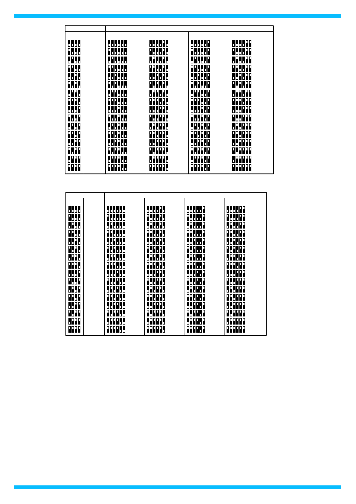
DI -SWITCH CONFIGURATION TABLES
SW1
54321
EPROM *
SW1
54321
TAB.1 – Input type settings
90 mV
200 mV
800 mV
10 V
20 mA
Res. 2KW
Res. 500W
Pt100
Ni100
Pt 1K
Ni 1K
Pot. <500W
SW1
54321
Tc J
Tc K
Tc R
Tc S
Tc T
Tc B
Tc E
Tc N Pot. <50KW
External
SW1
6
TAB.3
Options
Internal
CJC
3 wires
2/4 wires
RTD/RES

Zero
SW3
4321
Default
0
150
300
350
400
450
500
550
600
650
700
750
800
Full Scale
SW2
6543
Default
500
520
540
560
580
600
620
640
660
680
700
720
740
760
780
7 8
SW2
6543
800
820
840
860
880
900
920
940
960
980
1000
1025
1050
1075
1100
7 8
SW2
1175
1200
1225
1250
1275
1300
1325
1350
1375
1400
1425
1450
1475
1500
SW2
1650
1700
1750
1800
1850
1900
1950
2000
2000
2000
2000
2000
250
200
1125 1550
2000
2000
2000
16001150
W W W W W
6
543 7 8 6
543 7 8
TAB.4c – Resistance < 2 Ko m input scale settings.
Zero
SW3
4321
Default
0
10
40
50
75
100
125
150
175
200
225
250
300
W
Full Scale
SW2
6543
Default
50
55
60
65
70
75
80
85
90
95
100
110
115
120
W
7 8
SW2
125
130
135
140
145
150
155
160
165
170
175
180
185
190
195
SW2
220
230
240
250
260
270
280
290
300
310
320
330
340
350
SW2
380
390
400
410
420
430
440
450
460
470
500
500
30
20
200 360
480
490
500
370210
105
W W W
6543 7 8 6543 7 8 6543 7 8
TAB.4d – Resistance < 500 o m input scale settings
Zero
SW3
4
321
Default
0
15
30
35
40
45
50
55
60
65
70
75
80
%
Full Scale
SW2
6543
Default
5
6
8
10
12
14
16
18
20
22
24
26
28
30
32
%
7 8
SW2
34
36
38
40
42
44
46
48
50
52
54
56
58
60
62
%SW2
68
70
72
74
76
78
80
82
84
86
88
90
92
94
%SW2
100
100
100
%
100
100
100
100
100
100
100
100
100
25
20
64 96
100
100
100
9866
6543 7 8 6543 7 8 6543 7 8
TAB.4e – Potentiometer input scale settings
Zero
SW3
4
321
Default
0
1.5
3
3.5
4
4.5
5
5.5
6
6.5
7
7.5
8
Full Scale
SW2
6543
Default
5
5.2
5.4
5.6
5.8
6
6.2
6.4
6.6
6.8
7
7.2
7.4
7.6
7.8
7 8
SW2
6543
8
8.2
8.4
8.6
8.8
9
9.2
9.4
9.6
9.8
10
10.25
10.5
10.75
11
7 8
SW2
11.75
12
12.25
12.5
12.75
13
13.25
13.5
13.75
14
14.25
14.5
14.75
15
SW2
16.5
17
17.5
18
18.5
19
19.5
20
20
20
20
20
2.5
2
11.25 15.5
20
20
20
1611.5
mA mA mA mA mA6543 7 8 6543 7 8
TAB.4f – Current input scale settings
Zero
SW3
4321
Default
0
1.5
3
3.5
4
4.5
5
5.5
6
6.5
7
7.5
8
Volt
Full Scale
SW2
6
543
Default
0.5
0.6
0.8
1
1.2
1.4
1.6
1.8
2
2.2
2.4
2.6
2.8
3
3.2
Volt
7 8
SW2
3.4
3.6
3.8
4
4.2
4.4
4.6
4.8
5
5.2
5.4
5.6
5.8
6
6.2
Volt SW2
6.8
7
7.2
7.4
7.6
7.8
8
8.2
8.4
8.6
8.8
9
9.2
9.4
Volt SW2
10
10
10
Volt
10
10
10
10
10
10
10
10
10
2.5
2
6.4 9.6
10
10
10
9.86.6
6
543 7 8 6
543 7 8 6
543 7 8
TAB.4g – Voltage input scale settings

Datexel reserves its rig ts to modify totally or in part t e c aracteristics of its products wit out notice at any time .ED.02.15-R.01
DIMENSIONS (mm)
90
112
PGRM
12,5
INSTALLATION INSTRUCTIONS
T e device is suitable for fitting to DIN rails in t e vertical position.
For optimum operation and long life follow t ese instructions:
When the devices are installed side by side it may be necessary to
separate them by at least 5 mm in the following cases:
- If panel temperature exceeds 45°C.
- Use of ig power supply value ( > 27 Vdc ).
- Use of one or bot current outputs.
- Use of active current input.
Make sure t at sufficient air flow is provided for t e device avoiding to
place raceways or ot er objects w ic could obstruct t e ventilation slits.
Moreover it is suggested to avoid t at devices are mounted above
appliances generating eat; t eir ideal place s ould be in t e lower part
of t e panel.
Install t e device in a place wit out vibrations.
Moreover it is suggested to avoid routing conductors near power signal
cables (motors, induction ovens, inverters etc...) and to use s ielded
cable for connecting signals.
LIGHT SIGNALLING
LED COLOUR STATE DESCRI TION
PWR GREEN ON
OFF
Device powered
Device not powered
BLINKING Wrong dip-switc es settings
ALARM RED ON
OFF
Trip alarm active
Trip alarm not active
DAT 4530 / t100 / 0 ÷ 200 °C / 4 ÷ 20 mA / 4 ÷ 20 mA / 3wires
Input type
Input scale
Out A scale
Options
Out B scale
HOW TO ORDER
T e device is provided as requested on t e Customer's order.
Refer to t e section “Programming” to determine t e input and output ranges.
In case of t e configuration is not specified, t e parameters must be set by t e user.
ORDER CODE EXAM LE:
POWER SUPPLY
OUTPUT A
OUTPUT B
INPUT
ISOLATION STRUCTURE
TRIP
ALARM
CONNECTIONS
OWER SU LY(*)
IN UT SIDE OUT UT SIDE
I
G
RTD/RES 2W
I
H
G
RTD/RES 3W
+
-
Vdc
U
V
L
I
+
TC
mV
+
E
C
V
+
-
D
F
+
-
TX
I
H
G
ot
Rload
+
S
T
V
Vout
CHANNEL B
Rload
+
Q
R
Iout
mA
Rload
+
R
T
Iout
+
Vdc
Rload
+
O
V
Vout
CHANNEL A
Rload
+
M
N
Iout
mA
Rload
+
N
Iout
+
TRI ALARM
A
B
I
H
G
RTD/RES 4W
L
F
C
+
-
assive mA input
Connected to active
current loop
Active mA input
Connected to passive
current loop
(*) Note: for UL installation the
device must be powered using a
power supply unit classified
NEC class 2 or SELV
Table of contents
Other Datexel Media Converter manuals


