aevit 2.0 User manual

AEVIT 2.0 MOUNTING BRACKETS INSTALL MANUAL
AEVIT 2.0 Mounting Brackets Installation Manual
Table of Contents
1. Introduction 1
1.1 Overview 1
1.2 Installing the Mounting Ball Onto Input Devices 1
2. Primary Inputs 2
2.1 General Information 2-1
2.2 Mounting Base Installation - Floor 2-1
2.3 Mounting Base Installation - Door 2-3
2.4 Generic Adjustment Installation 2-5
2.5 Other Mounting Options 2-7
3. Secondary Inputs 3
3.1 General Information 3-1
3.2 Display Bracket Installation 3-1
3.3 Secondary Function Switches 3-2
4. Service Requirements 4
5. Before Operating... 4

AEVIT 2.0 MOUNTING BRACKETS INSTALL MANUAL
1. INTRODUCTION Mounting Brackets
EMC provides many dierent options for mounting the AEVIT 2.0 devices.
These devices include the AEVIT 2.0 Primary Input Devices, the AEVIT 2.0
Display, and secondary switch options. This manual will show the recom-
mended mounting options for all of these devices. Also provided in this
manual are a few variations of the recommended mounting options that
may better suit your client.
This installation manual is broken down into two (2) major sections. The
rst section focuses on the Primary Input Mounting Brackets. This section
will show how to install brackets for mounting Steering and Gas/Brake
input devices. The second section will focus on Secondary Input Mounting
Brackets. This section deals with the mounting of the AEVIT 2.0 Display and
secondary activation switches.
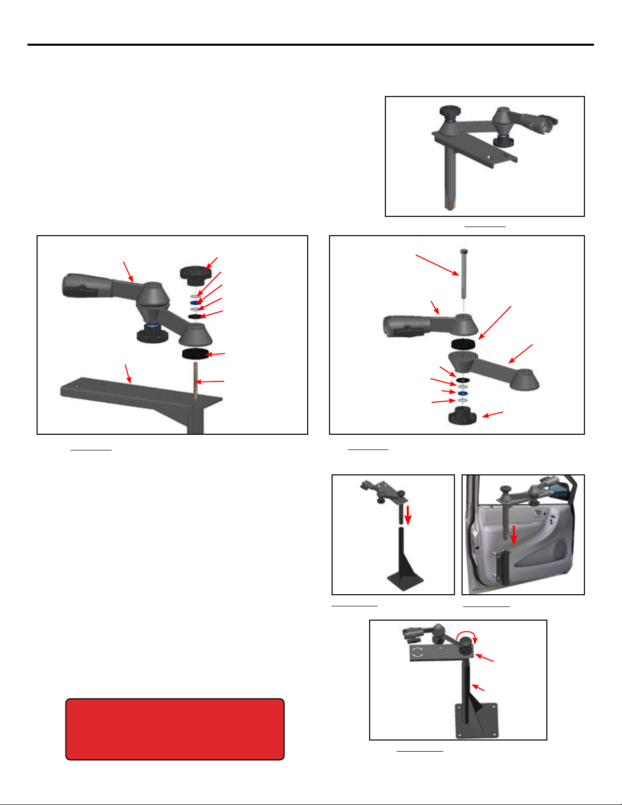
All EMC mounting options provide versatility with the use of ball-and-socket mounting brackets. Mounting Balls will
need to be attached to the input devices and the corresponding mounting brackets will have the mating sockets.
Therefore, the rst step in installing any of the input devices is to install the mounting ball to the bottom of them.
Each Input Device Install Kit should have a Mounting Ball and a Mounting Ball hardware kit that contains the follow-
ing:
(4) 10-32 x 1/2” Safety Torx Screws (1) Safety Torx Bit
(4) #10 Internal Tooth Lock Washers (1) Container of Blue Loctite®
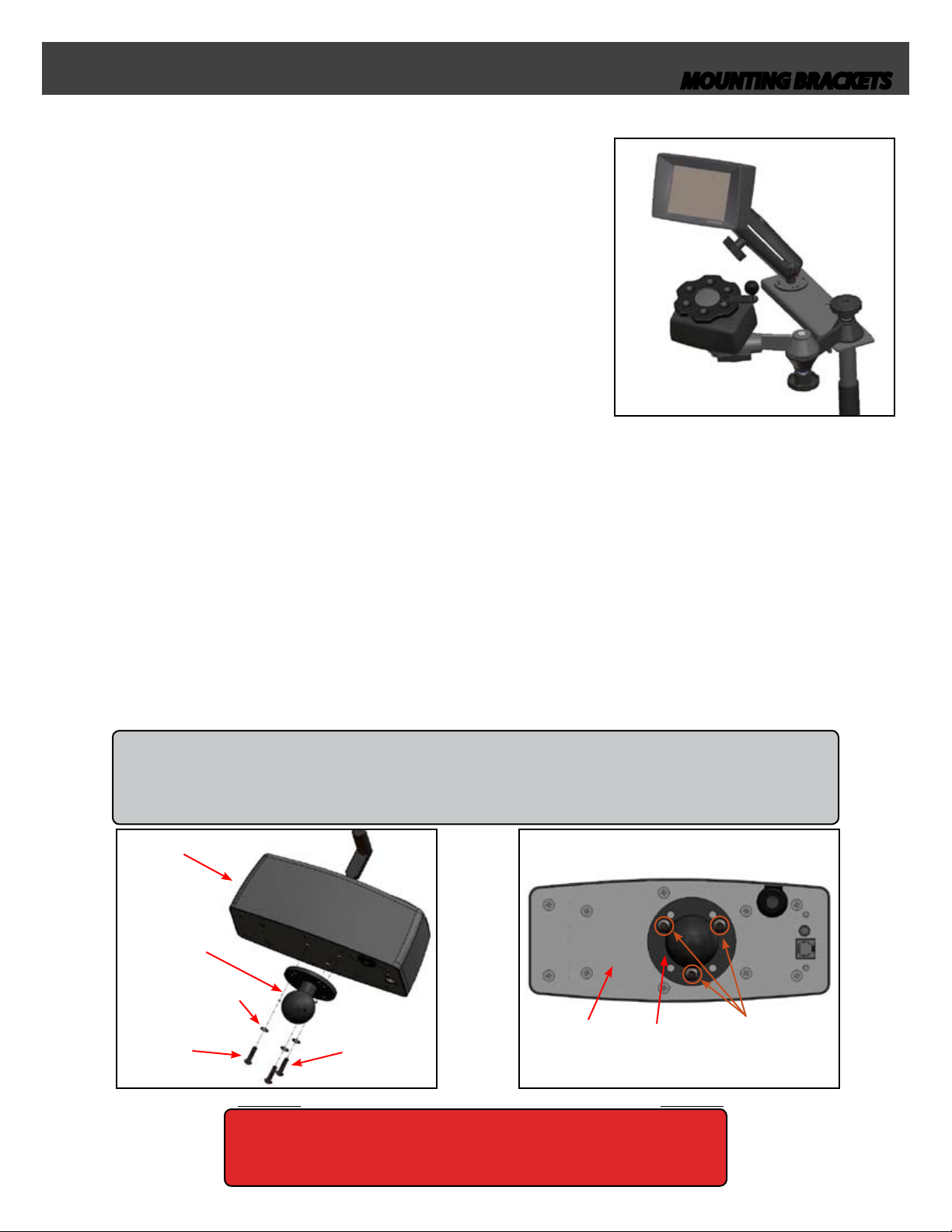
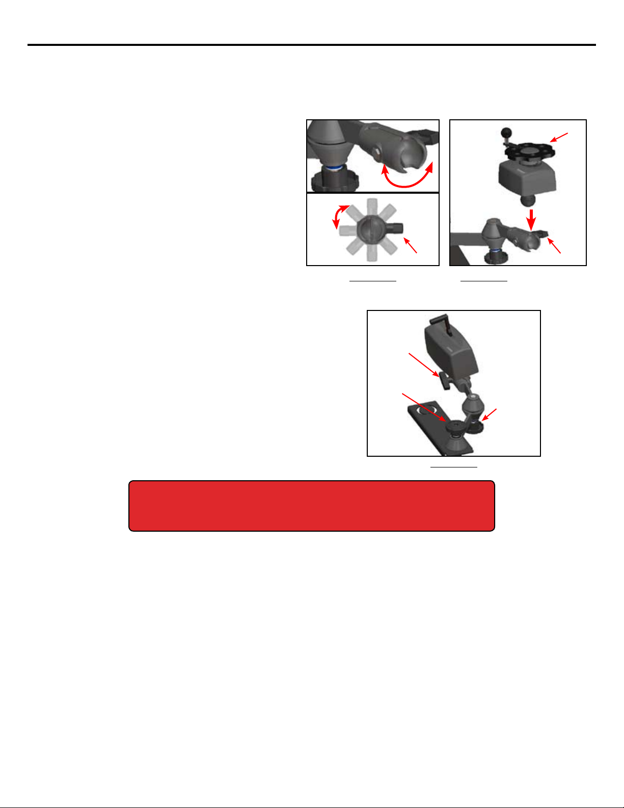
Install the Mounting Ball onto the input device using (3) 10-32 x 1/2” safety torx screws, (3) internal tooth lock washers
and the Blue Loctite® as shown in Figure 1. In order to install the (3) safety torx screws you will need to use the sup-
plied safety torx bit. There are (7) pre-drilled holes on the mounting ball. Figure 2 shows which holes should be used
to mount the ball onto the input device.
ALL AEVIT 2.0 PRIMARY INPUT DEVICES AND THE AEVIT 2.0 DISPLAY ARE DESIGNED TO HAVE THE SAME
MOUNTING BALL SCREW PATTERN. THEREFORE, THIS INSTALLATION STEP SHOULD BE PERFORMED FOR
ALL INPUT DEVICES LEVER, WHEEL, JOYSTICK... AND THE AEVIT 2.0 DISPLAY.
BE SURE TO PROPERLY TIGHTEN THE SCREWS TO THE PROPER TORQUE
SETTING OF 2.0 FTLBS AND USE BLUE LOCTITE®.
DEvICE
DEvICE
BALL
INTERNAL TOOTH
LOCk wASHERS
SCREwS
BALL
use these (3)
Mounting
holes
1.1 OVERVIEW
1.2 INSTALLING THE MOUNTING BALL ONTO INPUT DEVICES
use Blue
loctite®
1

AEVIT 2.0 MOUNTING BRACKETS INSTALL MANUAL
2. PRIMARY INPUT Mounting Brackets
The primary input section will describe how to install the mount-
ing brackets for the Primary Inputs which include: Digital Lever,
Wheel, and single and dual axis Joysticks. As the name states, these
devices perform the tasks of operating the primary functions of the
vehicle: Steering and Gas/Braking. Generally, the Gas/Brake controls
are installed on the left hand side of the driver and utilize the door
mounting bracket system and the steering controls are installed
on the right hand side of the driver and utilize the oor mounting
bracket system. However, only the base plate of each mounting
system is dierent (See gure to the right for mounting system com-
ponents). Sections 2.2 and 2.3 will go into detail about installing the
bases of the Floor and Door mounting systems and section 2.4 will
discuss the generic adjustment section installation. Finally, section
2.5 will discuss other mounting options.
Before installing the Floor Mounting system, verify that the following components are included with the BRKT-AEVIT-
FLR mounting kit:
(1) Floor Base Plate (4) 3/8” x 2” Hex Head Bolts
(1) Input Device Articulating Swivel Brkt (8) 3/8” Flat Washers
(1) Input Device Mounting Ball (4) 3/8” Lock Nuts
(1) Mounting Ball Hardware Kit
2.1 GENERAL INFORMATION
2.2 MOUNTING BASE INSTALLATION FLOOR BRKTAEVITFLR
FLOOR BASE
SECTION
wHAT NOT TO DO
INSTALL THE EMC MOUNTING BRACKETS IF ALL COMPONENTS ARE NOT PROVIDED IN THE KITS.•
DEVIATE FROM ANY STEPS SHOWN IN THESE INSTRUCTIONS UNLESS APPROPRIATE. (I.E.“OTHER MOUNTING•
OPTIONS” SECTION).
INSTALL THIS EQUIPMENT IF YOU ARE UNSURE ABOUT ANY STEP IN THESE INSTRUCTIONS.•
THESE INSTRUCTIONS SHOULD BE READ THOROUGHLY BEFORE ATTEMPTING TO INSTALL THIS
EQUIPMENT. FAILURE TO DO SO COULD CAUSE THESE MOUNTING BRACKETS TO BE INSTALLED
INCORRECTLY LEADING TO AN ACCIDENT RESULTING IN SERIOUS INJURY AND/OR DEATH.
IF ANY OF THESE COMPONENTS ARE NOT INCLUDED WITH THE BRKTAEVITFLR, CALL THE EMC
SERVICE DEPARTMENT. DO NOT ATTEMPT TO INSTALL WITHOUT ALL PARTS.
21

AEVIT 2.0 MOUNTING BRACKETS INSTALL MANUAL
22
PRIMARY INPUT
2.2 MOUNTING BASE INSTALLATION FLOOR BRKTAEVITFLR
CONTINUED
BEFORE DRILLING IN THE OEM VEHICLE, CHECK ALL AREAS ABOVE AND BELOW
TO AVOID DRILLING THROUGH WIRE HARNESSES OR OTHER EQUIPMENT.
Determine the location for the Floor Base Plate. This will change depending on the needs of the client. EMC recom-
mends that it be mounted between the two front seats with the webbing facing towards the passenger seat and the
AEVIT 2.0 Chassis be mounted partially on top of it as shown in the gures below (See your vehicle specic AEVIT 2.0
Installation Manual for information on mounting the AEVIT 2.0 Chassis). The Floor Base Plate and the AEVIT 2.0 Chassis
should also be mounted as far forward in the vehicle as possible. This will reduce the overall footprint of the system
and allow the client to move their wheelchair in and out of the driver’s area more eectively. It is also very important
to make sure that the Floor Base Plate does not extend to the left into the drivers area as this will interfere with the cli-
ent’s wheelchair movements.
Once the location of the mounting bracket is selected, drill (4) 3/8”
holes through the oor.
Mount the Floor Base Plate to the oor of the vehicle using (4) 3/8”x 2”hex head bolts, (8) 3/8”at washers, and (4)
Lock nuts. Once the Base Plate is mounted, skip to section 2.4 for the adjustment and input device installation infor-
mation.
WHEN MOUNTING THE AEVIT 2.0 CHASSIS IN THIS CONFIGURATION, YOU WILL NEED TO
PROVIDE FOUR 4 SPACERS WHICH ARE AT LEAST 1/2”THICK TO RAISE THE CHASSIS OVER
THE FLOOR BASE PLATE AND ITS MOUNTING BOLTS. THESE SPACERS ARE SHOWN IN
FIGURE 4B.
SPACERS
Mount the
floor Base
plate with
the weBBing
towards the
passenger’s
seat
WEBBING
Mount the
aevit 2.0
chassis
over the
floor Base
plate
verify that
the floor
Base plate
does not
extend into
the driver’s
area

AEVIT 2.0 MOUNTING BRACKETS INSTALL MANUAL
23
PRIMARY INPUT
2.3 MOUNTING BASE INSTALLATION DOOR BRKTAEVITDOOR
Before installing the Door Mounting system, verify that the following components are included with the BRKT-AEVIT-
DOOR mounting kit:
(1) Door Base Plate (4) 5/16” x 3” Hex Head Bolts
(1) Input Device Articulating Arm Bracket (6) 1/4” x 1” Hex Head Bolts
(1) Upper Pole Mounting Plate (4) 5/16” Lock Washers
(1) Input Device Mounting Ball (6) 1/4” KEP Nuts
(1) Mounting Ball Hardware Kit (4) Base Plate Spacers
(5) Bolt Caps (1) Additional Spacer*
IF ANY OF THESE COMPONENTS ARE NOT
INCLUDED WITH THE BRKTAEVITDOOR, CALL
THE EMC SERVICE DEPARTMENT. DO NOT AT
TEMPT TO INSTALL WITHOUT ALL PARTS.
Once all components are veried as present, the Door Base Plate can be attached directly to the door as shown in Fig-
ure 5 below. This universal plate will be mounted to the OEM driver’s door with no less than (5) bolts and locknuts for
the vehicles shown. The four bosses protruding out from the door plate will go through the door panel to accept the
Quick Adjust Upper Pole. Figure 6 shows the Door Base Plate and references possible mounting holes for individual
vehicle manufacturers.
DOOR BASE
PLATE
BASE PLATE
SPACERS
UPPER POLE
MOUNTING PLATE
DOOR BASE
PLATE BOSSES
C - Chrysler F - Ford T - Toyota H - Honda
C F H
C F T H
C F H
C F H T s
C F sH
T
T
F T
Door Panel Mounting
Clip Area
(Holes marked with F s & T s will require the additional spacer* behind the plate.)
BOLTS
THE DOOR BASE PLATE IS DESIGNED TO AVOID OEM DOOR
PANEL MOUNTING CLIPS FOR ALL VEHICLES. THESE VOID AREAS
MUST BE CONSIDERED WHEN PLACING THE PLATE FOR HOLE
DRILLING.
This rendering shows how the door mounting sys-
tem will eventually go together. The Door Base Plate
is hidden behind the panel with the (4) protrusions
and/or spacers coming through the OEM door panel.
ALL MOUNTING HARDWARE AND FASTENERS MUST BE PROP
ERLY TIGHTENED TO PREVENT UNINTENDED MOVEMENT OF
THE INPUT DEVICES AND MOUNTING BRACKETS. FAILURE TO
OBSERVE THIS WARNING MAY RESULT IN AN ACCIDENT CAUS
ING SERIOUS INJURY AND/OR DEATH.

AEVIT 2.0 MOUNTING BRACKETS INSTALL MANUAL
24
PRIMARY INPUT
2.3 MOUNTING BASE INSTALLATION DOOR BRKTAEVITDOOR
CONTINUED
Once the holes are drilled, cut away any
plastic areas that will interfere with the door
plate being mounted parallel with the door.
Be sure that the areas that were cut away
remain neat.
You may need to use other tools to remove
the carpet on the other side of the panel.
Remove the driver’s door panel and mark
the area where the Door Base Plate will be
mounted. See hole diagram on previous
page. Mount the door plate with no less than
(5) 1/4-20 x 1” bolts and locknuts. After the
plate is mounted, mark and drill (4) 5/8” holes
for the standos.
THE 4 5/16 X 3” HEX HEAD BOLTS ARE LONG ENOUGH
FOR USE WITH THE SPACERS AT FULL LENGTH. IF YOU CUT
THE SPACERS, HOWEVER, YOU WILL NEED TO PROVIDE
A SMALLER BOLT THAT WILL OFFER AT LEAST 1/2” OF
ENGAGEMENT INTO THE DOOR BASE PLATE BOSSES.
Your mounting system comes with (4) spacers that
can be cut to any length to bring the Upper Pole
Mounting Plate out from the door, depending on the
vehicle.

AEVIT 2.0 MOUNTING BRACKETS INSTALL MANUAL
25
PRIMARY INPUT
2.4 GENERIC ADJUSTMENT INSTALLATION BRKTAEVITFLR & BRKTAEVIT
DOOR
Now that the bases are installed, the adjustment section can now be
mounted. Both the Floor Mounting System and the Door Mounting
System will come with the same adjustment section. Therefore, this
section pertains to both installs. The adjustment section comes pre-
assembled from EMC; however, Figures 8 & 9 show exactly how they are
assembled in case you need to disassemble or replace a component. The
main components of the Adjustment Section are the Input Device Ar-
ticulating Swivel Bracket and the Quick Adjust Upper Pole (Figure 8). The
main components of the Input Device Articulating Swivel Bracket are the
Input Device Swivel Bracket and the Extension Arm (Figure 9).
BOLT
SwIvEL BRACkET
wASHER
ExTENSION
ARM
kNOB 2
THREADED ROD
INg SwIvEL BRACkET
BRACkET ASSEMBLY
Once the Adjustment Section Assembly is inserted into
the base, it can be adjusted vertically 4”. Once it is at the
correct height, tighten Adjustment Knob 1 thoroughly
(Figure 12). Verify that the Quick Adjust Upper Pole will
not move under normal operating conditions.
Insert the Adjustment Section into either the Floor Base
Plate or the Door Base that was installed in sections 2.2
and 2.3. Adjustment Knob 1 may need to be loosened for
the Adjustment Section to t into the base. When Adjust-
ment Knob 1 is loosened, it pushes down on the threaded
rod located inside of the Quick Adjust Upper Pole. This,
in turn, loosens the wedge at the bottom of the Quick
Adjust Upper Pole.
tighten
adjustMent
knoB 1 to lock
Quick adjust
upper pole
in place
SECTION
FAILURE TO TIGHTEN ALL ADJUSTMENT KNOBS
COMPLETELY COULD CAUSE AN ACCIDENT RE
SULTING IN SERIOUS INJURY AND/OR DEATH.

AEVIT 2.0 MOUNTING BRACKETS INSTALL MANUAL
26
PRIMARY INPUT
2.4 GENERIC ADJUSTMENT INSTALLATION BRKTAEVITFLR & BRKTAEVIT
DOOR CONTINUED
The Input Device Articulating Swivel Bracket, as
the name implies, swivels in 45O increments to
allow for multiple angles for the Input Devices
(Figure 13). To install the Input Device, simply
place the ball of the Input Device into the socket
of the Input Device Horizontal Swivel Bracket and
tighten, using the“T” handle as shown in Figure
14.
Once the Input Device is installed, it can be tted for
the client. Adjustment Knobs 1 & 2 are used to con-
gure the Input Device Articulating Swivel Bracket
such that the client can operate the input device both
comfortably and eectively. The “T” handle can also
be used to adjust the angle of the input device to the
client’s needs. Once the input device and Input Device
Articulating Swivel Bracket is in the correct position,
tighten all adjustments such that neither the input
devices nor the mounting systems move under normal
operating conditions.
kNOB 2
FAILURE TO TIGHTEN ALL ADJUSTMENT KNOBS COMPLETELY COULD CAUSE AN
ACCIDENT RESULTING IN SERIOUS INJURY AND / OR DEATH.
O

AEVIT 2.0 MOUNTING BRACKETS INSTALL MANUAL
27
PRIMARY INPUT
2.5 OTHER MOUNTING OPTIONS BRKTAEVITFLR & BRKTAEVIT DOOR
REVERSING ADJUSTMENT KNOB 2
The Adjustment Section of the mounting systems
comes pre-assembled with Adjustment Knob
2 on the bottom of the Input Device Articulat-
ing Swivel Bracket as shown in Figure 16. In this
position, the knob will not interfere with the
input device. However, if the client wishes to have
Adjustment Knob 2 on top of the bracket (Figure
17), the following steps should be followed for
reversing it.
Unscrew Adjustment Knob 2 from the 4” hex head bolt
shown in Figure 18. Remember to keep track of the hard-
ware and the order of the at washers when disassembling
the Input Device Articulating Swivel Bracket.
FAILURE TO TIGHTEN ALL ADJUSTMENT KNOBS COMPLETELY COULD CAUSE AN
ACCIDENT RESULTING IN SERIOUS INJURY AND / OR DEATH.
Insert the 4” hex head bolt into the bottom of the Input
Device Articulating Swivel Bracket and attach the remain-
ing hardware to the bracket in the following order:
-3/8” fender washer
-3/8” at washer
-3/8” bearing
-3/8” at washer
-Adjustment Knob 2
See Figure 19 for the full assembly.
BOLT
SwIvEL BRACkET
wASHER
ExTENSION
ARM
kNOB 2
BOLT
SwIvEL BRACkET
wASHER
ExTENSION
ARM
kNOB 2
Once Adjustment Knob 2 is reversed, repeat step 4 from
the Generic Adjustment Section to t the client. Once the
client is tted, tighten all adjustments such that neither
the input devices nor the mounting systems move under
normal operating conditions.

AEVIT 2.0 MOUNTING BRACKETS INSTALL MANUAL
28
PRIMARY INPUT
2.5 OTHER MOUNTING OPTIONS BRKTAEVITFLR & BRKTAEVIT DOOR
CONTINUED
CUTTING THE QUICK ADJUST UPPER POLE
If only one input device is being mounted to the Quick
Adjust Upper Pole, the extra length of the bracket can
be removed. EMC recommends that the cut be made
3” from the“pole side” of the quick adjust upper pole as
shown in Figure 20.
Figure 21 shows an application where cutting the
Quick Adjust Upper Pole was necessary in order for the
mounting bracket to t the door panel.
FAILURE TO TIGHTEN ALL ADJUSTMENT KNOBS
COMPLETELY COULD CAUSE AN ACCIDENT RE
SULTING IN SERIOUS INJURY AND / OR DEATH.
DEBUR ALL EDGES AFTER CUTTING THE QUICK
ADJUST UPPER POLE.
ATTACHING ONLY THE INPUT DEVICE SWIVEL BRACKET
There are a few applications where the entire Input Device
Articulating Swivel Bracket is not needed and only the Input
Device Swivel Bracket is used (Figure 22). If this is the case,
the installer will have to provide the following hardware:
(1) 3/8” x 2 1/2” Grade 8 Hex Head Bolt
(2) 3/8” Flat Washers
(1) 3/8” Lock Nuts
Some of the hardware from the Input Device Articulating
Swivel Bracket will be used as well. EMC recommends that
the installer review page 2-5 to familiarize themselves with
the components that make up the Input Device Articulating
Swivel Bracket assembly.
SwIvEL BRACkET
ONLY

AEVIT 2.0 MOUNTING BRACKETS INSTALL MANUAL
29
PRIMARY INPUT
2.5 OTHER MOUNTING OPTIONS BRKTAEVITFLR & BRKTAEVIT DOOR
CONTINUED
ATTACHING ONLY THE INPUT DEVICE SWIVEL BRACKET CONTINUED
Remove the Input Device Articulating Swivel
Bracket from the Quick Adjust Upper Pole. (See
Figure 8, Page 2-5 for information on this assem-
bly). Also, remove the Input Device Swivel Bracket,
(1) 2” Dia rubber washer, and Adjustment Knob
1 (Figure 9, Page 2-5). These components will be
used in step 5 of this section.
At this point, there will be a threaded rod protrud-
ing from the Quick Adjust Upper Pole. Insert the
3/8” Flat Washer and Adjustment Knob 1 onto the
Threaded rod (Figure 23a). This hardware will be
used to lock the Quick Adjust Upper Pole in place
much like step 2 Page 2-5. Tighten the adjustment
knob and make a mark on the threaded rod such
that it can be cut as to not protrude from the top
of the adjustment knob when the installation
is completed (Figure 23b). This can be done by
simply making a mark on the rod at the top of
Adjustment Knob 1 and then removing the knob
and washer and cutting the threaded rod approxi-
mately 1/4”beneath the mark. (Figure 24a).
Reinstall Adjustment Knob 1 and (1) 3/8” at
washer as shown in Figure 23a
wASHER
THREADED
ROD
Once the Quick Adjust Upper Pole is in position, a
3/8” thru hole will need to be drilled into it. Notice
in Figure 25, there is a support webbing under-
neath the Quick Adjust Upper Pole. The 3/8” thru
hole can be drilled anywhere along either of the
two (2) dotted lines shown in Figure 26. Basically,
the 3/8” hole will need to be drilled 7/8” from ei-
ther side of the Quick Adjust Upper Pole such that
the nylon and at washers of the Input Device
Swivel Bracket will not interfere with the support
webbing underneath.
7/8”
wEBBINg
ALONg EITHER DOTTED
LINE SHOwN
7/8”
a
PRIOR TO CUTTING THE THREADED ROD, THREAD
1 3/8” NUT NOT INCLUDED ONTO THE THREAD
ED ROD, THEN MAKE THE CUT. AFTER THE ROD IS
CUT, REMOVE THE 3/8” NUT FROM THE CUT END OF
THE ROD TO CLEAN/DEBUR THE THREADS.
b
Make cut Mark flush with the
top of the adjustMent knoB
ab
Figure 24b shows what this assembly should look
like after cutting the threaded rod.
Make cut
here
(see hint)

AEVIT 2.0 MOUNTING BRACKETS INSTALL MANUAL
210
PRIMARY INPUT
2.5 OTHER MOUNTING OPTIONS BRKTAEVITFLR & BRKTAEVIT DOOR
CONTINUED
ATTACHING ONLY THE INPUT DEVICE SWIVEL BRACKET CONTINUED
The Input Device Horizontal Swivel Bracket, as the
name implies, swivels in 45O increments to allow for
multiple angles of the Input Devices (Figure 28).
To install the Input Device, simply place the ball of
the Input Device into the socket of the Input Device
Horizontal Swivel Bracket and tighten using the“T”
handle as shown in Figure 29. The completed install
should resemble Figure 30.
Mount the Input Device Horizontal Swivel Bracket
to the Quick Adjust Upper Pole using (1) 3/8” x 2.5”
Grade 8 Bolt, (1) 2” Dia. Rubber Washer, (1) 3/8” Flat
Washer, and (1) 3/8” Lock Nut. The 3/8” bolt, 3/8” at
washer and 3/8” lock nut will need to be supplied by
the installer while the 2” Dia rubber washer and Input
Device Swivel Bracket are from the disassembled In-
put Device Articulating Swivel Bracket (Step 1, Page
2-9)
SwIvEL BRACkET
(FLAT SIDE DOwN
FLAT wASHER
Tighten the 3/8”Lock Nut such that there is NO
MOVEMENT DURING NORMAL OPERATION OF
THE INPUT DEVICE.
FAILURE TO TIGHTEN THE 3/8” LOCK NUT COM
PLETELY COULD CAUSE AN ACCIDENT RESULT
ING IN SERIOUS INJURY AND/OR DEATH.
O

AEVIT 2.0 MOUNTING BRACKETS INSTALL MANUAL
3. SECONDARY INPUT Mounting Brackets
The secondary input section will describe how to install the mount-
ing brackets for the AEVIT 2.0 Display and switches to operate the
secondary functions of the vehicle. Generally, the AEVIT 2.0 Display
is mounted to the same Quick Adjust Upper Pole as the AEVIT 2.0
Wheel as shown in Figure 31; however, with the hardware provided,
it can be installed just about anywhere. Section 3.3 will discuss
mounting the switches that control the secondary functions of the
vehicle. These include: Digitone 2.0, VIC 2.0, plus others.
Before installing the Display Mounting system, verify that the following components are included with the BRKT-
AEVIT-DISP mounting kit:
(1) Display Vertical Support
(2) Input Device Mounting Balls
(1) Mounting Ball Hardware Kit
3.1 GENERAL INFORMATION
3.2 DISPLAY BRACKET INSTALLATION BRKTAEVITDISP
IF ANY OF THESE COMPONENTS ARE NOT IN
CLUDED WITH THE BRKTAEVITDISP, CALL THE
EMC SERVICE DEPARTMENT. DO NOT ATTEMPT
TO INSTALL WITHOUT ALL PARTS.
Attach (1) mounting ball to the AEVIT 2.0 Display (see
page 1 for instructions). Determine a location to attach the
second mounting ball to the Quick Adjust Upper Pole. This
bracket was designed such that the mounting ball can be
mounted anywhere along the Quick Adjust Upper Pole.
Mark and Drill (3) 3/16” thru holes into the Quick Adjust
Upper Pole and install the second mounting ball to the
bracket (hardware not included).
Mount the Display to the Display Vertical Support and the
Vertical Support to the Mounting Ball that was installed in
step two (Figure 32).
The standard length of the Display Vertical Support is 8” .
Other lengths are available on special order. Contact EMC
SALES at (207) 512-8009 for more information.
vERTICAL
BALL
HARDwARE FOR
INSTALLINg SECOND
ALL MOUNTING HARDWARE AND FASTENERS MUST BE PROPERLY TIGHTENED TO PRE
VENT UNINTENDED MOVEMENT OF THE INPUT DEVICES OR DISPLAY. FAILURE TO
OBSERVE THIS WARNING MAY RESULT IN AN ACCIDENT CAUSING SERIOUS INJURY AND/
OR DEATH.
31

AEVIT 2.0 MOUNTING BRACKETS INSTALL MANUAL
32
SECONDARY INPUT
3.3 SECONDARY FUNCTION SWITCHES
The most commonly used switch to operate secondary functions
is the 1.5” Push-Button switch (Figure 33). This switch can be used
to operate the 2.0 Digitone, VIC 2.0 and other single secondary
functions. The same bracket system used to mount the AEVIT 2.0
Display can be used to mount this single switch.
Attach the 1.5”Push-Button switch to a Mounting
Ball using a small piece of double sided tape.
BALL
SwITCH
Attach this assembly and the second mounting
ball to the Vertical Support as shown in Figure 35.
The completed assembly should look like Figure
36.
Finally, this assembly can be mounted anywhere
convenient for the client to access. A common
place to locate this switch is on the “B” Pillar as
shown in Figure 37. In this position, a client could
easily use their elbow to activate the switch. How-
ever, any place where the Mounting Ball can be
securely attached can be used. EMC recommends
that a bracket be fabricated and mounted to a sup-
port pillar of the vehicle and the Mounting Ball be
attached to it (hardware not included). Figure 38
shows an example of this.
vERTICAL
SECOND
BALL
FABRICATED
BRACkET
(ATTACHED
DIRECTLY TO THE
HARDwARE FOR
INSTALLINg SECOND

AEVIT 2.0 MOUNTING BRACKETS INSTALL MANUAL
4. SERVICE REQUIREMENTS
4
The AEVIT 2.0 Mounting Systems does not have any mandatory service requirements. However, the client should
periodically check to make sure that all adjustment knobs are tightened completely. Please contact EMC Service if you
have any questions regarding the AEVIT 2.0 Mounting Systems.
Mounting Brackets
EACH MOUNTING SYSTEM WAS DESIGNED TO BREAKAWAY UNDER LOADS THAT EXCEED THE NORMAL FORCES EX
ERTED ON THE INPUT DEVICE. SINCE NO AEVIT 2.0 INPUT DEVICE REQUIRES A FORCE OF MORE THAN 4 POUNDS, IF THE
BRACKETS ARE INSTALLED CORRECTLY AND TIGHTENED PROPERLY, THESE BRACKETS WILL REMAIN STATIONARY UNDER
NORMAL OPERATING CONDITIONS.
HOWEVER, IF AN EXCESSIVE FORCE IS APPLIED TO THESE BRACKETS I.E. ACCIDENTAL IMPACTS WITH WHEEL CHAIRS,
ETC..., THESE BRACKETS ARE DESIGNED TO BREAK AWAY. IF THERE ARE ANY FORCED MOVEMENTS OF THE MOUNTING
BRACKETS SUCH AS THIS, IT IS EXTREMELY IMPORTANT THAT ALL ADJUSTMENTS BE RETIGHTENED, IF POSSIBLE.
THE REASON FOR THIS IS WHEN THE BRACKETS “BREAK AWAY” AND ARE FORCED BACK INTO THEIR ORIGINAL POSITION,
MOST ADJUSTMENT KNOBS BECOME LOOSENED IF BLUE LOCTITE® IS NOT APPLIED AND THEREFORE WOULD NEED TO
BE RETIGHTENED.
FAILURE TO OBSERVE THIS WARNING MAY RESULT IN THE CLIENT OPERATING THE VEHICLE WITH LOOSE MOUNTING
BRACKETS WHICH COULD CAUSE AN ACCIDENT RESULTING IN SERIOUS INJURY AND/OR DEATH.
5. BEFORE OPERATING... Mounting Brackets
It is extremely important for your client to be fully informed about the capabilities (and limits) of these mounting
bracket systems. These mounting bracket systems were designed to provide nearly unlimited options for mounting
of the input devices. By adjusting both Adjustment Knobs, it is possible for the client to have their input device in any
position where they can operate it both eectively and comfortably. Refer to section 2.4 if you client wishes to have
the mounting system adjusted and refer to section 2.5 for other mounting options that your client may wish to utilize.
Once the client is tted for the input devices and they are satised with the input device’s position, time should be
taken to go over the following NOTES, CAUTIONS and WARNINGS with them.
EMC RECOMMENDS THAT ONCE THE CLIENT IS SATISFIED WITH THE LOCATION AND POSITION OF THE INPUT DEVICES,
ALL ADJUSTMENT KNOBS SHOULD BE REMOVED AND BLUE LOCTITE® SHOULD BE APPLIED TO THE THREADS. AFTER THE
LOCTITE® IS APPLIED, THE KNOBS SHOULD BE REINSTALLED AND TIGHTENED COMPLETELY. THIS WILL PREVENT THEM
FROM LOOSENING UNDER NORMAL OPERATION AND ACCIDENTAL IMPACTS SEE WARNING #3.
IT IS EXTREMELY IMPORTANT FOR THE CLIENT KNOW THAT IT IS THEIR RESPONSIBILITY TO VERIFY THAT ALL INPUT DEVIC
ES AND MOUNTING BRACKETS ARE SECURE BEFORE OPERATING THE VEHICLE. THEY SHOULD BE INFORMED ABOUT ALL
POSSIBLE ADJUSTMENTS SO THEY CAN CHECK FOR LOOSE BRACKETS EACH TIME THEY ENTER THE VEHICLE.
FAILURE TO OBSERVE THIS WARNING MAY RESULT IN THE CLIENT OPERATING THE VEHICLE WITH LOOSE MOUNTING
BRACKETS WHICH COULD CAUSE AN ACCIDENT RESULTING IN SERIOUS INJURY AND/OR DEATH.
THE ADJUSTMENT SECTION OF THE MOUNTING SYSTEMS IS DESIGNED FOR USE WITH ONE OR MORE 2”RUBBER WASH
ERS SEE FIGURES 8 & 9 PG 24. THE PURPOSE OF THIS RUBBER WASHER IS TO FULLY SECURE TWO MOUNTING BRACK
ETS. IN ORDER TO SUFFICIENTLY SECURE THE MOUNTING BRACKETS TOGETHER AND COMPRESS THE RUBBER WASHER,
IT IS IMPORTANT THAT ALL ADJUSTMENT KNOBS BE TIGHTENED FULLY SUCH THAT THERE IS NO MOVEMENT UNDER
NORMAL OPERATING CONDITIONS.
DAMAGE MAY OCCUR TO THE ADJUSTMENT KNOBS IF THEY NEED TO BE REMOVED AFTER THE BLUE LOCTITE® IS APPLIED.
MAKE SURE THE CLIENT IS SATISFIED WITH THE INPUT DEVICE POSITION BEFORE APPLYING THE BLUE LOCTITE®.

AEVIT 2.0 MOUNTING BRACKETS INSTALL MANUAL
NOTES:
Table of contents
Popular TV Mount manuals by other brands

Sanus Systems
Sanus Systems New VisionMount VLMF109-B1 Brochure & specs

Mountup
Mountup MU6013A instruction manual

Rawinternational
Rawinternational PT2 instruction manual

Gianni Industries
Gianni Industries Z-600N installation instructions

Dynex
Dynex DX-TVM111 Quick setup guide

Garden Treasures
Garden Treasures 1050004276 quick start guide